Featured Post

Beolover SyncDrive: DC Platter Motor Replacement for Beogram 4002 and 4004 (Type 551x and 552x)

Late Beogram 4002 and the 4004 (Types 551x and 552x), which have DC platter motors instead of the earlier synchronous AC motors usually suff...

Saturday, October 24, 2020

Beomaster 2400 Type 2902 - Canada Project Capacitor Replacement Part 1

 I got through all of the work replacing old capacitors in the Beomaster 2400 main board (over 60 capacitors) and volume control board (2 capacitors).

Here is the Beomaster 2400 again prior to replacing the electrolytic capacitors.


This restoration was different than my usual Beomaster 2400 capacitor restorations.
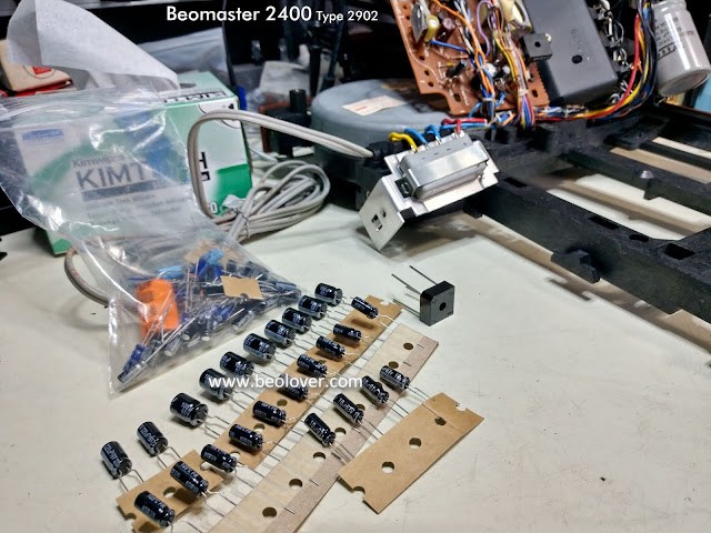
The owner of this Beomaster had already purchased a Beomaster 2400 recapping kit from Martin Olsen.  It has been a long time since I used someone's capacitor kit but why not? The capacitors are good capacitors so I wouldn't want to waste them.


Martin's kit also included a new bridge diode for the incoming AC power so I will replace that.
This kit has all of the replacement capacitors for the Beomaster 2400 electrolytic capacitors except the two large 5000uF, 50V reservoir capacitors so I will add those two.

The kit also does not contain replacements for the Beomaster 2400 tantalum capacitors. The tantalum capacitors are typically still okay but I normally replace them as the restored audio component often has a long trip back to its owner. Replacing them is a bit of additional insurance to avoid having to send a problem component back and forth.

Of course you will find a lot of discussion on various audio forums about whether to replace tantalum capacitors with tantalums or a different type like electrolytic or polyester.  For capacitance values of 4.7uF and smaller I prefer using WIMA MKS polyester capacitors so that is what I will be doing here.

Here is the Beomaster 2400 after the recapping task of the main board and volume control board have been completed.


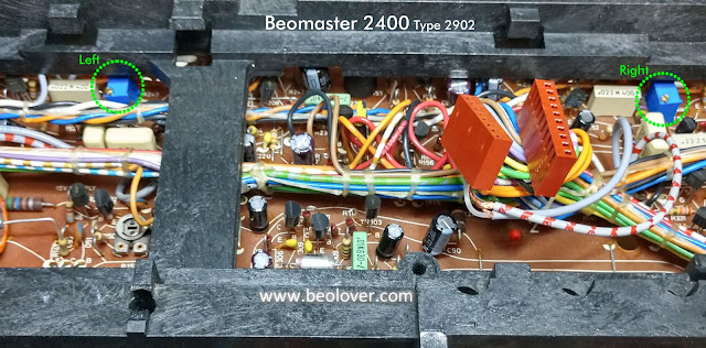
I also replaced the left and right channel no-load current adjustment trimmers with new multi-turn, sealed type trimmers.  There were three capacitors, the black ones in the photo, that were capacitors that had been replaced by someone else previously.  They measured good but I changed them so that all of the capacitors starting with this restoration are the same age. One thing to note...one of the previously changed capacitors was 33uF instead of the original 22uF capacitance value.  Martin's kit calls for the original 22uF capacitor which is also what I have always used. I have no idea why the 33uF was put in here.

For my own knowledge base I always take a little extra time and measure each capacitor I remove. I just want to know what state it is actually in.  On this Beomaster 2400 all of the electrolytic capacitors except the large ones were out of tolerance. The 1uF capacitors almost all measured over 2uF. The 2.2uF capacitors were either at 3.5uF or just over 4uF.  The 4.7uf were around 6uF. 

The tantalums were all still within their 20% tolerances but a lot of them were close to the upper limit.

The reservoir capacitors measured good but I still always replace them to insure against future problems.

Here are the two reservoir capacitors before replacing them.


Here is the after photo.


The reservoir capacitors are a little tricky to change. B&O connected a number of ground wires to the common point of the reservoir capacitors. The positive and negative DC connection points each have three wires connected as well. New power supply capacitors I use have small posts so connecting the number of wired the Beomaster requires means creating some good terminal solder points.

I joined two terminal posts together for the ground wires and soldered all of the ground wires to that ground terminal. I soldered the positive DC voltage wires to another terminal then soldered that to the positive post of the reservoir capacitor assembly. I also connected the negative DC voltage wires to a terminal on the negative post.

That makes for a really solid reservoir capacitor assembly and the wires are neatly connected.




Two of the black ground wires go to the speaker jacks.  The original wires are short and don't have much room to operate with.  One usually always breaks off when raising and lowering the main board during the recapping process. I always replace those with some longer wires that can handle the main board raising and lowering.


Here are the before and after photos of the volume control board.


Here is a photo of the two new multi-turn, sealed trimmers that will be used to adjust the no-load current of the output amplifiers.


The adjustment knobs for the trimmers are easier to access than the old trimmers.

The next restorations task is to do the capacitor replacement on the removable board with the tone controls, filters and FM tuning.  That will be followed by cleaning the slider controls and the replacement of the lamps.


No comments:

Post a Comment

Comments and suggestions are welcome!