Recently I functionally restored a Beomaster 2400 (Type 2902) that I received from a customer in Connecticut. This post discusses the process.
The next step in this project was to design LED replacements for the 15 indicator bulbs that are located beneath the pretty front panel of the Beomaster.
Several of these bulbs function not only as indicator lights, but are functional components of the circuit. In particular the seven program selector bulbs also serve as triggers for the muting circuitry that suppresses the pops during program source changes, like when one changes from Phono to a FM station etc...They produce a voltage spike during the heating up of their filaments when turned on. This spike triggers the muting circuitry of the Beomaster. This means that a burnt out bulb not only ceases to indicate the chosen source, but it also causes loud pops when the user changes to this particular input source.
Therefore, it is desirable replacing the bulbs with LEDs. LEDs last much longer than incandescent bulbs, which burn out 'naturally' after a while as the filaments slowly evaporate when the bulbs are burning. Another advantage of LEDs is that they emit much less heat, and this means the heat-bleaching of the red and green diffusers that cover the bulbs is stopped after LEDs are installed. The LEDs will also alleviate this issue since the replacement boards were designed with red or green LEDs, which do not need color filters in the first place.
This shows the complete set of LED Replacements for Beomaster 1900 and 2400 Indicator Light Bulbs:
The top row shows the two boards for the volume indicator on the left. The three T-shaped boards to the right replace the bulbs that illuminate the balance/treble/bass sliders. The bottom row shows the LED boards for the stereo indicator/program selector/tuning lights board.
Installation:
This shows the stereo indicator/program selector/tuning light board still installed with the colored diffusers in place:
This board is easily removed since it is connected with wire to board connectors that come in from the solder side of the board:
After unplugging the board the filter cabinets assembly can be removed, which reveals the light bulbs underneath:
This photo shows one of the bulbs already replaced with my very first LED replacement prototype. This prototype did not work since I did not understand yet how the muting function is triggered by the program source bulbs. Once I understood that the muting function is triggered by the changing resistance of the bulb filament as its temperature changes during powering up of the bulb I came up with a second prototype that simulated the voltage spike that is generated by this resistance change:
Prototyping is fun!...;-). After a few more iterations I finally arrived at a set of LED assemblies that faithfully maintained the functionality of the bulbs. This shows them together with the PCB with the bulbs removed:
The first step after unsoldering the bulbs is to solder short wire clippings into the solder points of the bulbs:
Here a detail shot:
Once the wire clippings are in place the LED boards can be soldered to them:
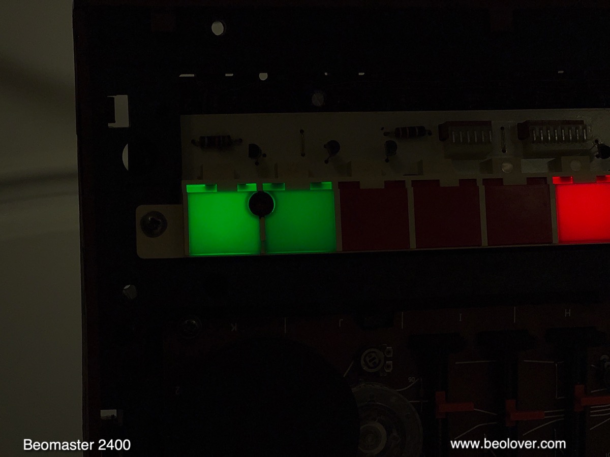
A detail picture of some of the program indicators in place:
After replacing the bulbs I verified the proper function of the LED boards. The primary concern of the program indicators is that they properly trigger a short muting period of about 0.5 sec whenever the indicator comes on.
Before I replaced the bulbs I measured the original muting signals. The oscilloscope shot below shows the bulb induced voltage spike across 5R3 (yellow trace) on PCB 5 that holds the bulbs. The blue curve shows the resulting signal at the collector of 3TR29 (3TR6 in the older 2400/1900 versions with 16 step volume control), which indicates that a ~0.5 sec muting period was triggered by the voltage spike:
After replacing the bulbs with my LED boards, I measured this curve:
When the LED board is turned on a voltage spike occurs, which triggers an identical muting period. The main difference is that the voltage spike across 5R3 starts out from a much lower voltage due to the much lower current through the LEDs. This is of no consequence since the muting period is triggered by the spike, which causes the charging of 3C30 (3C6 in the older 16 step volume control versions), which in turn defines the timing of the muting period. A listening test with the new boards confirmed this assessment since program source changes were completely quiet. So all good in the program selector indicator department!
On to the tuning indicators ("balance lights" - they help with centering the tuner on a particular station frequency): These LED boards had to be designed to actually match the current drawn by the bulbs in order to maintain the same behavior during FM station selection. The service manual suggests adjusting the balance between the two indicators whenever work is done on a Beomaster 2400/1900. For this, test point 2TP3 (white grabber) needs to be connected to GND before the trimmer 2R31 (screw driver) can be adjusted:
Before the adjustment the installed LEDs were unevenly lit under this test condition:
Turning the trimmer a bit yielded a symmetrical illumination:
This concluded the installation of the LED boards on PCB 5.
Next came the replacement of the two bulbs in the volume indicator:
This board is connected with three soldered wires, i.e. cannot be unplugged:
It can be left connected for the installation. This shows the two bulbs after removal of the filter cabinets:
I replaced them with two LED boards:
These boards need to be installed in a ~30 degree angle relative to the PCB:
The final task was to replace the three bulbs in the cabinets that illuminate the three sliders:
This board is also soldered directly to wires
and can also be left connected. I forgot to take a picture right after I removed the filter cabinet, so here one that already shows a prototype LED board installed in lieu of one of the bulbs:
For installing the three LED panels the same process is used like for PCB 5. First solder in short wire pieces
and then put the LED panels in place:
And then it was time to do a first test with all the LED boards in place:
Beolovely!
Then it was time to put this Beomaster back together. But before I did that I installed four new rubber feet. The original ones were all gone:
I installed a set of four rubber feet obtained from the dksoundparts store:
Then I put the enclosure panels back together. This shows the re-assembled unit:
And with the control panel opened up:
The LED bulb replacements look very nice and I would say pretty much indistinguishable from the original bulbs (except that all indicators work again!...;-). I will play this Beomaster a bit more and then it will be time to send it back to its owner.


.jpg)


No comments:
Post a Comment
Comments and suggestions are welcome!