Featured Post

Beolover SyncDrive: DC Platter Motor Replacement for Beogram 4002 and 4004 (Type 551x and 552x)

Late Beogram 4002 and the 4004 (Types 551x and 552x), which have DC platter motors instead of the earlier synchronous AC motors usually suff...

Thursday, June 26, 2025

Beomaster 2400 (2902): Replacement of Indicator Bulbs with Drop-In Beolover LED Assemblies

Recently I functionally restored a Beomaster 2400 (Type 2902) that I received from a customer in Connecticut. This post discusses the process.

The next step in this project was to design LED replacements for the 15 indicator bulbs that are located beneath the pretty front panel of the Beomaster.

Several of these bulbs function not only as indicator lights, but are functional components of the circuit. In particular the seven program selector bulbs also serve as triggers for the muting circuitry that suppresses the pops during program source changes, like when one changes from Phono to a FM station etc...They produce a voltage spike during the heating up of their filaments when turned on. This spike triggers the muting circuitry of the Beomaster. This means that a burnt out bulb not only ceases to indicate the chosen source, but it also causes loud pops when the user changes to this particular input source.

Therefore, it is desirable replacing the bulbs with LEDs. LEDs last much longer than incandescent bulbs, which burn out 'naturally' after a while as the filaments slowly evaporate when the bulbs are burning. Another advantage of LEDs is that they emit much less heat, and this means the heat-bleaching of the red and green diffusers that cover the bulbs is stopped after LEDs are installed. The LEDs will also alleviate this issue since the replacement boards were designed with red or green LEDs, which do not need color filters in the first place.

This shows the complete set of LED Replacements for Beomaster 1900 and 2400 Indicator Light Bulbs:

The top row shows the two boards for the volume indicator on the left. The three T-shaped boards to the right replace the bulbs that illuminate the balance/treble/bass sliders. The bottom row shows the LED boards for the stereo indicator/program selector/tuning lights board.

Installation:

This shows the stereo indicator/program selector/tuning light board still installed with the colored diffusers in place:
This board is easily removed since it is connected with wire to board connectors that come in from the solder side of the board:
After unplugging the board the filter cabinets assembly can be removed, which reveals the light bulbs underneath:
This photo shows one of the bulbs already replaced with my very first LED replacement prototype. This prototype did not work since I did not understand yet how the muting function is triggered by the program source bulbs. Once I understood that the muting function is triggered by the changing resistance of the bulb filament as its temperature changes during powering up of the bulb I came up with a second prototype that simulated the voltage spike that is generated by this resistance change:
Prototyping is fun!...;-). After a few more iterations I finally arrived at a set of LED assemblies that faithfully maintained the functionality of the bulbs. This shows them together with the PCB with the bulbs removed:
The first step after unsoldering the bulbs is to solder short wire clippings into the solder points of the bulbs:
Here a detail shot:
Once the wire clippings are in place the LED boards can be soldered to them:
A detail picture of some of the program indicators in place:
After replacing the bulbs I verified the proper function of the LED boards. The primary concern of the program indicators is that they properly trigger a short muting period of about 0.5 sec whenever the indicator comes on.
Before I replaced the bulbs I measured the original muting signals. The oscilloscope shot below shows the bulb induced voltage spike across 5R3 (yellow trace) on PCB 5 that holds the bulbs. The blue curve shows the resulting signal at the collector of 3TR29 (3TR6 in the older 2400/1900 versions with 16 step volume control), which indicates that a ~0.5 sec muting period was triggered by the voltage spike:
After replacing the bulbs with my LED boards, I measured this curve:
When the LED board is turned on a voltage spike occurs, which triggers an identical muting period. The main difference is that the voltage spike across 5R3 starts out from a much lower voltage due to the much lower current through the LEDs. This is of no consequence since the muting period is triggered by the spike, which causes the charging of 3C30 (3C6 in the older 16 step volume control versions), which in turn defines the timing of the muting period. A listening test with the new boards confirmed this assessment since program source changes were completely quiet. So all good in the program selector indicator department!

On to the tuning indicators ("balance lights" - they help with centering the tuner on a particular station frequency): These LED boards had to be designed to actually match the current drawn by the bulbs in order to maintain the same behavior during FM station selection. The service manual suggests adjusting the balance between the two indicators whenever work is done on a Beomaster 2400/1900. For this, test point 2TP3 (white grabber) needs to be connected to GND before the trimmer 2R31 (screw driver) can be adjusted:
Before the adjustment the installed LEDs were unevenly lit under this test condition:
Turning the trimmer a bit yielded a symmetrical illumination:
This concluded the installation of the LED boards on PCB 5.

Next came the replacement of the two bulbs in the volume indicator:
This board is connected with three soldered wires, i.e. cannot be unplugged:
It can be left connected for the installation. This shows the two bulbs after removal of the filter cabinets:
I replaced them with two LED boards:
These boards need to be installed in a ~30 degree angle relative to the PCB:
The final task was to replace the three bulbs in the cabinets that illuminate the three sliders:
This board is also soldered directly to wires
and can also be left connected. I forgot to take a picture right after I removed the filter cabinet, so here one that already shows a prototype LED board installed in lieu of one of the bulbs:
For installing the three LED panels the same process is used like for PCB 5. First solder in short wire pieces
and then put the LED panels in place:
And then it was time to do a first test with all the LED boards in place:
Beolovely! On to replacing the volume control device, which contains the final remaining incandescent bulb! Stay tuned.


Tuesday, June 24, 2025

Michigan Beogram 8002 Restoration

It is time for another Beogram 80002 restoration project.  This one comes from Michigan.

These are always a favorite Bang & Olufsen turntable to restore.  

Here is the unpacking...


The creative packing method is a little different than mine but it is sound and did a good job of protecting the Beogram on its journey here. 

The next step was to open the Beogram 8002 up and assess what the restoration will be like.


The first thing I noticed was that the Beogram's floating chassis was not locked down all the way.
Only one of the three chassis lockdown screws was engaged.

On the other two, one was not engaged while the other one was missing the lockdown screw.

The front leaf spring for the floating suspension has some odd glue on the screw used to set the floating suspension height. Perhaps someone wanted to make sure no one adjusted its position?


The black, metal cover beneath the tonearm home position has the usual deteriorated double-sided tape B&O used on these components back in the early 1980's.  That is always an expected part of these restorations.


I will set the pieces needing replacement mounting tape aside for now.

Another piece that falls into that group is the silver colored, metal deck.
It was completely loose as usual.  Removing it revealed the little spring the fits underneath the metal deck for static discharge was missing.  I will install a replacement spring for that.


The remaining part of the Beogram 8002 assessment requires opening the cabinet up to remove the turntable inner components.

To do that, three metal hangers for the suspension have to be detached from the three metal leaf springs.


With the floating chassis released, it can be slid to the right so the Beogram cabinet can clear the tonearm assembly.


Once the cabinet lid is tilted out of the way the inner components can be disconnected and removed.
It is easier and safer (for the health of the cabinet) to remove the inner components for the restoration tasks.


For the floating chassis removal the audio output assembly (rear, left in the cabinet) must be unscrewed and removed.  The wire harnesses from the floating chassis components to the main board (PCB 1)  also need to be disconnected.


The floating chassis metal hanger clips (to the leaf springs) should be collected and bagged up so they don't get lost.


After removing the floating chassis I discovered the missing lockdown screw.


That was a pleasant find.  I was hoping the static discharge spring might also show up...but no luck.

Here is the empty Beogram 8002 cabinet.  Ready to be stored away while work on the inner components is performed.


...and here are the removed Beogram 8002 turntable components.


This is where I discovered a couple of problems with this Beogram 8002.

Nothing unsurmountable but a couple of crucial things that will have to be repaired before this Beogram 8002 can function again.

The first problem is with the thin, plastic clip that holds one side of the tangential arm position sensors to the floating chassis.

The plastic piece is broken off.  Surprisingly, like the missing lockdown screw, the broken plastic piece was in the cabinet.


The bad thing about this broken piece is that it can't be glued back on. The edge of the position sensor board would just break the glue joint again.

The B&O molded plastic base is still there but I don't see any way to remove it without breaking it.

I will have to mull over that problem and decide what to do.
Worst case...I do have spare floating chassis assemblies.  However, I think I will try to come up with a 3D printed solution first.

The second crucial problem on this Beogram 8002 is with the spindle that moves the tangential arm assembly forward and back.

The plastic/nylon spindle nut has a broken edge.

That edge is required for the bracket that connects the arm assembly to the spindle nut.
As the servo motor turns the spindle nut travels along the spindle, taking the tangential arm assembly with it.  The Beogram 8002 will not work without a completely intact spindle nut.


There are a couple of solutions for the broken spindle nut.
I have some spare spindle nuts from other Beogram units and Beolover has made a 3D printed version of the spindle nut as well.

Other than the broken spindle nut and broken bracket for the arm position sensor, everything else looks fine.


Thursday, June 5, 2025

Beomaster 2400 (2902): Functional Restoration and Test

This post discusses the functional restoration of a Beomaster 2400 (Type 2902) that I received from a customer in Connecticut. My first assessment of the unit is posted here.

The elegant flat design of this Beomaster type required putting most circuitry onto a single board, which is connected via wiring harnesses that are directly soldered to the board. Some of the auxiliary boards already received wire to board connectors, which helps a bit with the disassembly. 

After unsoldering the FM receiver front end the main PCB swings out into a 'service position' of sorts. In order to protect the many fragile wires that connect to it I had the idea putting the entire setup on a large Lazy Susan rotary platform that I fashioned from a pizza cutting board and a 20" turntable bearing. This allows accessing the PCB from both sides without continuously bending the wires:

The biggest task is the replacement of the close to 100 electrolytic capacitors that this design carries. after more than 40 years these capacitors are often out of spec and need to be replaced. Some of them are inside the EMI shields that are soldered to the board. This shows the stereo decoder can:
Its 'lid' is on the backside of the board:
I unsoldered both shields to get to the single electrolytic cap inside:
I replaced it
and put the shields back into place. Next came the remote control receiver:
Removal of the can revealed the electrlytic cap inside:
I replaced it
And put the can back into place. Next I focused on the small piggybacked board above the volume control assembly. It has four Ta capacitors on it:
This board is a circuit modification that became necessary after they realized that there were issues when using non-B&O tape decks with the Beomaster 1900/2400. This board changes the tape output signal levels compared to the original setup. Since the main board was already designed they elected to add this small PCB. I guess in those days it was a lot of work to change the design of a board due to the absence of digital design tools. The added board is soldered to the original component solder points and adds a few more components to the circuit. I unsoldered it from the main board to be able accessing the solder points of the capacitors:
This shows it with new capacitors:
I soldered the small board back in:
Then began the arduous task of replacing all the other electrolytic caps on the board. This simply involves unsoldering a couple then pulling them out and putting new ones in minding the correct polarity. After this was done, I replaced the two main reservoir capacitors:
I replaced them with modern 10000uF units that have the same form factor. The original units are 4700uF, but in this case 'more is better' applies since they act as current reservoirs for the amplifier. This shows the new ones soldered in place:
Here a shot of the rebuilt board:
All the replaced components:
While the main PCB is still in service position it is the perfect moment to get to the electrolytic capacitor in the FM front end:
Its covers come off easily:
And from the other side:
The single blue Ta electrolytic capacitor needs to be replaced:
This shows the new one implanted:
Then it was time to address the other PCBs. The board that sits behind the controls under the aluminum lid (PCB#4) has a few electrolytic capacitors on it:
I replaced them:
On to PCB#3, the volume control and oscillator board. This Beomaster 2400 was fitted with the upgraded 128 step volume control, which only has one Ta electrolytic capacitor on it (blue):
I replaced it:
This concluded the capacitor replacement process. 
An important item to address in these Beomasters are the quiescent current trimmers in the output amplifier design. With these trimmers the working point of the output transistors is adjusted. The problem is that when the trimmers resistance goes up the quiescent current increases. This means when the trimmers oxidize the output transistors can overheat and literally go up in smoke. So it is a great idea to replace them with modern encapsulated multi-turn trimmers. This shows the original single turn trimmers after I removed them:
I implanted new 220 Ohm 25-turn trimmers
in a way that their adjustment screws poke through the original adjustment orifices in the PCB:
I also installed small wire 'eyelets' on the emitter resistors, which allowed making a solid connection with the multimeter for adjusting the quiescent current:
The service manual advises an adjustment to 12 mV after the unit has warmed up. 
In the meantime I finally received a batch of 10 amp bridge rectifiers as replacement for the original 3 Amp unit that this Beomaster still had implemented. It is the black square to the left of the reservoir capacitor stabilizing the 15V rail:


The 10 amp replacement is a bit bigger than the original unit, i.e. the legs need to be bent together to fit into the original footprint:
This shows it installed:
After this I decided to try if I could get any sound out of the Beomaster and connected it to my bench speakers. But no luck. Only at fully turned up volume I was able to hear a faint radio station. It turned out that this was caused by a faulty balance slider, which had lost its contacts. This is a frequent issue with the old style sliders that can be recognized by the broad metal spine on which the plastic bridge with the contacts slides. I unsoldered the slider:
The next step was removal of the attached plastic foil with the display apertures. This is done by removing the small copper clamp that holds it to the top of the plastic bridge:
The next step was removal of the metal spine:

Once the spine is off, the old slider can be slid off. This shows the original slider still in place. One of the contacts has broken off. The replacement part from the dksoundparts store is shown next to it:
I replaced the original part with the new one:
After soldering it back into place the Beomaster played radio through the speakers. Time for some measurements! This shows my setup:
I usually use a homemade 8 Ohm speaker dump fitted with a -40dBV (1/100) attenuator that allows me to directly connect my QuantAsylum QA400 for analyzing the output signal. The QA400 can only take a maximum voltage of 4V at its inputs, while the speaker outputs of the Beomaster can easily exceed 30V amplitude at high volumes. Therefore a suitable voltage divider is necessary for such measurements.
My first measurement focused on characterizing the Total Harmonic Distortion (THD) of the unit. For this measurement I used a RIGOL wave generator for putting a 1 kHz 0 dBV (2.83Vpp) signal into the tape input. Then I set the Beomaster to the highest volume level that still yielded a non-clipped clean sine wave on the oscilloscope. This is the spectrum that was measured by the QA400 for the right channel (the left was very similar):

The QA400 calculated 0.19% THD from this graph. This makes sense: The voltage difference between the fundamental 1kHz frequency and its first harmonic at 2 kHz is about 55 dBV, which corresponds to a 562x smaller signal, or 0.17% distortion. 0.19% is close to the THD < 0.2% spec stated in the service manual. So far so good!
Another concern with any amplifier is its frequency response. It should typically be as linear as possible that the amplifier does not alter the sound of the signal that is amplified. For this measurement I set the balance, bass and treble sliders to their center positions and the loudness switch to 'off'. Using the FR setting of the QA400 and connecting its outputs to the tape input of the Beogram I measured these frequency response curves for the 20-20kHz range:

This seems pretty linear, and it can be expected that the amplifier will not superimpose any 'color' onto the amplified sound.
While I had this measurement setup in place I also set the bass and treble sliders to their minimum and maximum positions and these are the curves I measured:

In absence of a calibrated voltage dial I started the Beomaster with the volume preset set to high to have a reproducible volume setting. The adjustment ranges seem to be around ±12dB at the low end and maybe ±15dB at the top end. This is a bit less for the bass range than the value stated in the service manual: "Bass at 40Hz: ±18dB", while the treble range matches the stated value: "Treble at 12500Hz: ±15dB" fairly well. Not sure why the bass range is a bit off. Maybe this has to do with tolerances in the sliders or filter components in the tone control circuit.
Since I like listening to vinyl records, I also measured the frequency response of the phono input. It is always interesting to see how well the frequency response matches the RIAA de-emphasis curve. This is the graph I measured:

For this measurement I actually had to make a special cable with a 40 dBV (1/100) attenuator for connecting the QA400 outputs to the phono input of the Beomaster. Even at the lowest signal setting the QA400 output still produces a too large signal for phono inputs. Phono signals are around 100x weaker than standard high level input signals, i.e. amplitudes in excess of 10mV can already drive a RIAA pre-amp into saturation. 
The measured curves show the expected gain reduction between low and high frequencies. The RIAA curve suggests ±20dBV variations for both bass and treble ranges. The Beomaster RIAA seems to match this fairly well for the high frequencies where the gain drops by about 18dBV between 1 kHz and 20kHz. In the bass range the change is only about 10dBV, suggesting that bass frequencies are slightly under-amplified making the sound a bit brighter than it should be. Of course this could be compensated by setting the bass tone control slider a bit higher.
In practical terms, I already played a few records on my bench 4002 through this phono input and I thought they sounded pretty good. So maybe this is not a big issue.

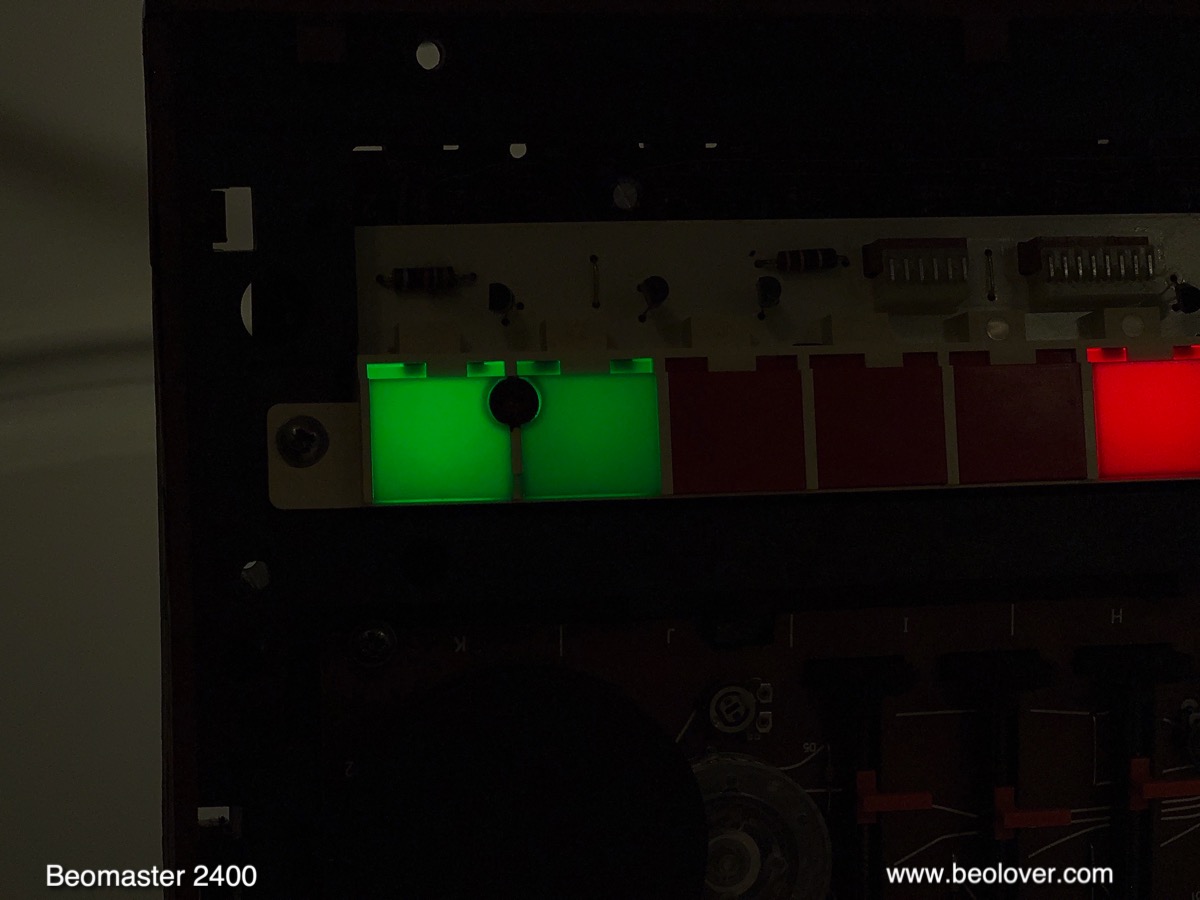
Stay tuned for my next post about this Beomaster, which will address replacing the front panel light bulbs with LEDs.