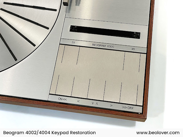
I recently received a Beogram 4000 from a Co-Beolover in Australia for a functional restoration. This shows the unit as received:

Sadly, the keypads were not taped down and so the big one in the center liberated itself on the way. Luckily, soon after it found a safe spot in the guts of the deck where it remained for the rest of the trip.
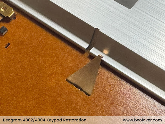
On the way to its safe spot it made a few small marks on the surrounding aluminum surfaces:

Over all, this Beogram got off lightly from this episode. I have seen units where such awol keys can create a lot of dings. One thing that saved this one is that there was a foam piece under the hood as I show in my packaging video. This reduced the available pathways for this key considerably.
So not too bad. Actually, this deck still looks fairly good with a nice platter (only a few dings on the rim, probably from earlier transportation without locking the transport locks):

I removed the aluminum panels and the platter and had a look below deck:

Immediately, some 'beautiful' work on the reservoir and motor capacitors became apparent!...;-):

I also found an earlier version of the Beolover Tracking Sensor LED Light Source for Beogram 4000 implemented:

There was also already a new carriage pulley installed:

One of the 'problem areas' of the Beogram 4000 is the awesome position indicator that shows where the needle is on the platter. This indicator has a fragile red plastic part that often gets damaged. I always remove this assembly when I work on a Beogram 4000 to lessen the likelihood for damaging it:

Often the very thin end breaks off when the assembly is removed by inexperienced operators. The thin end is the actual indicator that sticks deeply into the keypad cluster, and so can be broken off easily. In this case, however, the small plastic tab that holds the red plastic part on the metal assembly so it can slide forth and back as the carriage moves had broken off:

I am thinking how to fix this. Maybe a small 3D printed part that can be epoxied on.
After this visual inspection, I re-installed the keypad keys, switched the voltage selector to 110V and plugged it in. I pressed ON and the platter motor started rotating, but otherwise all functions were dead. None of the keys had any effect. No light from the sensor arm either.
This immediately suggested an issue with the 6V system, which powers the early-days hard-wired digital control logic (the 'brains' - one of the exciting aspects of this design!...;-) and part of the analog 'executive' control system of the deck.
I examined the power supply PCB and found a non-standard 500mA/T fuse installed that was blown.

I unsoldered the fuse and measured the signal between the two blue wires that connect to the 6V secondary of the transformer:

This is the trace I measured:

About 32V peak to peak AC. This is about what one would expect. This translates into about 11V RMS, which then is converted by the old-fashioned analog voltage regulator and a 2200uF capacitance into a stable 6V rail.
The presence of the proper input voltage and the blown fuse suggested a short in the 6V system. And indeed when I measured the resistance from the 6V reed relay output to GND I saw essentially 0 Ohm:

This suggested a direct short somewhere in the 6V system. Previously, I had never fully explored the 6V system on the Beogram 4000. It turned out to be a bit of a 'can of worms' with many yellow wires going to solder points on the main and keypad PCBs. This gets even more complicated since a lot of these wires go forth and back on the boards themselves to bridge circuit traces on the old single layer boards, as well as between the boards to complete circuits. This messy design is a consequence of the limited manufacturing techniques for electronic circuits of the early 1970s, which made such connections necessary.
This left basically only one option for isolating the problem: Unsolder all yellow wires one-by-one and keep an eye on the resistance between 6V rail and GND:

Even the solenoid transistor is connected to a yellow wire (which has nothing to do with the 6V system - I guess they ran out of wire colors...;-). I replaced the transistor anyway during my odyssey through the deck, just to make sure there was no additional source of short circuit (they often go bad due and I always replace them when I restore a Beogram). This shows the original transistor soldered in:

And after installing a modern TIP41C that has a higher voltage tolerance, which is advantageous for its battle with the solenoid sparks:

After a while I finally isolated the short circuit to be somewhere on the sensor arm assembly. Its light bulb is powered by the 6V system and, yes, there is a yellow wire going into the sensor arm assembly!
My measurements led me straight towards the sensor arm tube itself. And indeed this is where I finally found the short:
The person who worked on this deck apparently removed the sensor arm, probably due to a stuck damper to arm linkage, whose pivot point can only be re-lubricated when the sensor arm assembly is liberated. I think he removed the actual sensor arm tube when he tried to get the linkage out, which is usually obstructed by the sensor wiring. Then, when he put the arm assembly back together, he mistakenly installed one of the spiky lock washers that are used for securing the arm assembly to the carriage under the screw that holds the sensor arm tube to the assembly. In this process he managed to get the yellow wire caught by the spiky lock washer, which duly pierced the insulation:

This made me remember a formative moment of my late adolescence, when I brought my first car (a 1969 Renault 4 with 26HP and a 6V battery system...;-) to a mechanic due to a clogged up carburetor. When I asked 'how much', he said, "100 Deutschmark if you let me do it right away, and 200 DM if you try it first yourself"...;-). Sometimes it is just a good idea to let the experts take over. It saves everybody a lot of time.
I set out to fix the damage. This required unsoldering the end of the yellow wire from the carriage PCB and pulling it out so I could install a stretch of shrink tubing:

This shows the shrink tubing installed:

While I had everything apart I also removed the damper to arm linkage and put some synthetic grease on the pivot:

A slight tug on the small copper plate that is glued to the sensor arm assembly to facilitate lateral tonearm movement when the arm is up made it fall off:

I cleaned off the deteriorated double sided tape and epoxied it back into place:

Then I put everything back together.
I installed a new proper spec 400mA/T fuse in the secondary transformer circuit:

I also replaced the 6V regulator power transistor and the two electrolytic capacitors that are on the power supply board. This shows everything back in place:

Before I plugged the unit in I measured the resistance to GND at the output of the 6V reed relay for the record:

I guess when everything is o.k. one should see around 30 Ohms. Most of this current path is caused by the light bulb in the sensor arm.
I plugged the unit in and pressed ON. Now the sensor arm light came on and I was able to move the carriage left and right and also could activate the solenoid. Life signs!...;-).
Now comes the main part of the restoration! Stay tuned.