This post discusses the full functional restoration of a Beogram 4004 that I recently received from a customer in Illinois. My initial assessment of this Beogram is posted here.
This shows the unit without platter and aluminum panels:

As usual I started with the DC platter motor. They all need their Oilite bearings re-infused with oil. To get to the bearings the motor needs to be disassembled:

The bearings are the two small donuts on the black pad upfront. I immersed them in oil and pulled a vacuum. Immediately strong bubbling started:

While this slow process was going on, I focused on the remaining restoration tasks:
First came the restoration of the carriage. The moving parts of the carriage translation and arm lowering mechanisms are often impeded by old, hardened lubricants. They need to be removed and replaced with modern synthetic oils. This shows the mechanism in its original condition:

I removed the relevant parts for cleaning:

This shows the setup with the parts removed. It is a good idea to protect the fragile wiring on the bottom of the carriage with something soft like some foam or similar:

After an hour in the ultrasonic cleaner the parts were nice and shiny again:

Before I reassembled everything I installed a new damper gasket:

The original ones are often hardened and have a hard time sealing the plunger during the arm-down movement. This usually leads to inconsistencies in the arm lowering speed, which sometimes becomes un-dampened. Not a happy moment if you have a $800 cartridge on the arm!...;-).
This shows everything back in place:

There is one more item that needed to be lubricated and that was the damper-to-arm linkage. Its pivot point is located on the sensor arm assembly. The linkage can be spotted in this picture:

It is the lever that pokes out from the V-cut in the metal piece that is bolted to the counter weight of the tonearm. To get to the pivot point that needs to be re-lubricated the sensor arm needs to be taken out:

As usual the small copper plate that facilitates the lateral arm movement in up position was only loosely attached due to degraded double-sided tape. I glued it back into place with a dab of epoxy after scraping off the old tape:

The final item that I needed to address on the carriage was exchanging the tracking sensor light bulb with a LED replacement. This shows the original setup:

The black box in the center is the bulb housing. I removed it, which revealed the tracking sensor aperture:

This shows the black bulb housing in comparison to the Beolover Tracking Sensor LED Light Source for Beogram 4002 and 4004:

The small SMD LED is in the location of the filament of the original bulb. This ensures plug-and-play functionality. This shows the LED assembly in place:

This concluded the work on the carriage.
On to restoring the PCBs. First I focused on the main PCB. It has two power Darlingtons installed on its solder side. It is best to replace these transistors first while the board is still in place. This makes it easy to solder them in their proper location for bolting to the heat sinks. This shows 1IC1, originally usually a TIP120:

I usually replace these packages with stronger ones for a longer service life. The 5 Amp TIP120 can be replaced with its 8 Amp cousin TIP102:

The small added yellow item is a 100nF capacitor that needs to be put between emitter and GND. It quenches a strange high-frequency oscillation in the MHz range that occurs on the outputs of modern TIP packages in this ancient circuit configuration. If unattended, this oscillation can impede the function of the record detection circuit.
After replacing 1IC4 with a TIP107, I removed the board. This shows its component side in original condition:

A detail shot of the RPM section composed of National RPM relay and 33/45 RPM trimmers:

I exchanged all electrolytic capacitors, power transistors and the sensor arm transistor and its biasing resistor with modern components. I also installed a new Beolover RPM relay matching the original National relay footprint and replaced the RPM trimmers with modern 25-turn encapsulated units:

Here a detail shot of the renewed RPM section:
Next came the output board, which contains additional circuitry in the Beogram 4004 (compared to 4002) to enable remote control via a Beomaster 2400:

This shows the output relay section in more detail:

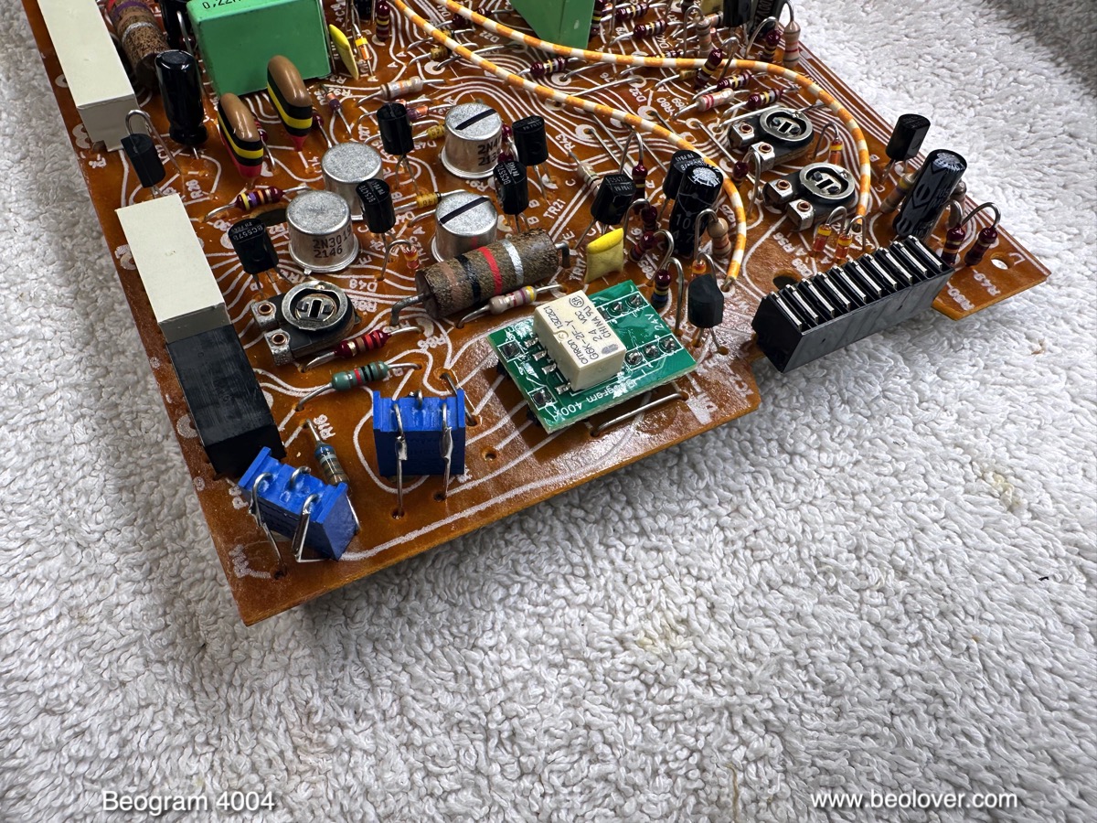
I replaced all electrolytic capacitors and the output relay with another Beolover National relay replacement:

This shows the relay section. I also installed a (red) switch behind the output socket that allows connecting system and signal grounds in case there is a hum in the output signal:

Next I removed the keypad cluster from the enclosure. The small panel above the keypad contains two more incandescent light bulbs that needed replacing with LEDs. This shows the panel removed from the keypad assembly and flipped over:

The bulbs are located behind the two white covers. Removal reveals the bulbs:

The two small green boards are Beolover RPM Panel LED Backlights for Beogram 4002 and 4004. They solder directly to the solder terminals for the original bulbs on the small PCB that makes the electrical connections between wiring and bulbs and trimmers:

This shows one of them magnified:

They do not obstruct the bulb covers, which can be reinstalled to preserve the look of this panel:

Next I removed the original reservoir capacitor from the enclosure:

And then it was time to attend to the as usual degraded transport lock bushings:

Their replacement requires removal of the floating chassis, leaving me with an empty enclosure. This is perfect since the fragments of the degraded bushings need to be vacuumed out. They can get lodged under the floating chassis impeding its motion, which reduces its ability to guard the record play from floor vibrations etc...This shows the vacuumed out and cleaned enclosure:

I removed the old bushings for the installation of a set of new Beolover Transport Lock Bushings for Beogram 4000, 4002, and 4004:

They are designed in two parts. This makes installation a snap: Simply push in one half from the bottom

and the other from the top:

And that is it:

Here an impression with the upper lock part added:

After re-installing the floating chassis I implanted a new Beolover reservoir capacitor assembly:

It fits both older dual-capacitance and newer single capacitance Beogram models. The Beogram 4004 only has the newer setup, hence all I needed to do was bolting the assembly in with the original screw that held the big capacitor can in place, and then solder the white and black wires to the respectively labeled solder terminals on the assembly.
The last light bulb to be replaced was in the sensor arm. This shows the sensor arm with pulled out bulb and photo-sensor compartment together with the Beolover Sensor Arm LED Light Source placed next to it:

And after replacing the bulb with the LED assembly:

While the keypad was still removed from the enclosure, it was a good moment to replace the cracked RPM panel clips. As so often they were broken out on both sides:


This seems to happen when the RPM panel is removed 'unprofessionally'. Luckily, there are nice replicas of these plastic parts available from the Beoparts-shop in Denmark. Here you can see old and new next to each other:

All one needs to do is moving the metal spring clips over from the original parts to the new ones:

This shows them bolted in:


While I had the keypad out I noticed that one of the wires (black) in the plug harness showed signs of rodent damage:

I unsoldered it on the PCB side and put a length of shrink tubing on the damaged part:

Then I put everything back together and tried to 'START<<' the deck. Unfortunately, all that happened was that the carriage moved a little and then immediately went back home after I let the START key go. This is usually an indicator that the '>>STOP' function is permanently engaged.
Since the Beogram 4004 can activate the STOP function also via the output board I exchanged the just restored output board with one I have that I know works properly. This did not change anything. Therefore I assumed the fault must be on the main PCB. This immediately suggested a dead 1TR13 transistor. TR13 is responsible for the STOP function in the electronic switch. Indeed, after extracting it my transistor tester suggested it is 'damaged':

I replaced it with a new BC547B and...drumroll...it worked. So I thought this was 'it' and I swapped my output board out for the original one.
This brought the phenomenon back! So it seemed that not only TR13 was dead but also transistor TR3 on the output board! This transistor translates the Beomaster 2400 remote 'STOP' signal into a signal the Beogram can understand. In this case the transistor tester found that it performed as a resistor!...;-):

After replacing TR3 with a BC547B the problem was finally fixed!
The next step was adjusting the bias trimmer I had installed for properly biasing the sensor arm transistor 1TR3. I set the bias to yield 4V at the collector of 1TR3:

Then I installed it on the component side of the board.
In the meantime the bubbling of the bearings had stopped, meaning that the oil infusion process had come to a conclusion. I broke the vacuum and extracted the bearings from the oil:

Then I put the motor back together. While it was out of its outer enclosure it was a good moment to repair the rodent damaged insulation on the blue and red wires:

Like with the keypad wire, I put shrink tubing over the damaged sections:

And then it was time for doing a 24 hrs RPM stability measurement. I did this with the BeoloverRPM device which, in its 'slow' mode' can log the RPM in 10s intervals over extended periods of time. This shows the BeoloverRPM in action:

This is the RPM graph I measured over approximately 24 hrs:

This is a pretty decent result. The motor still shows some minor RPM changes, but they are pretty small and will not be discernible. The reason for such variations in some restored motors is that the top bearing of the motor needs to get polished by the shaft in a new position. Due to the removal of the bearing for oil infusion it usually ends up in a slightly different alignment when re-installed. I usually mark the position before I disassemble the motor, but there is always a slight uncertainty and that seems to be enough. My experience is that such RPM variations tend to get better over time as the bearing adjusts to its new position.
The BeoloverRPM has a second mode, the 'fast' mode. In this mode of operation it plots an RPM measurement every time one of the platter ribs crosses under the sensor. This means every platter rotation yields 24 RPM measurements (there are 24 ribs spaced around each platter). This usually yields a repeating pattern every 24 measurement points as you can see on the small display on the unit:

This pattern is a measurement artifact caused by slight variations in the rib spacing around the platter. In other words every platter has a certain 'fingerprint' due to these minute distance variations between the ribs.
This repeating pattern is superimposed with a sine wave like pattern, which allows the determination of the 'wow and flutter' of the Beogram. This graph shows a ~120 seconds long measurement (corresponding to about 60 turns):

From this sine wave like fluctuation an approximate wow and flutter number of about 0.1% can be deduced. This is about 2x of the 0.05% number stated in the service manual. My suspicion is that this discrepancy is a result of the entirely different way this was measured in the pre-microcontroller 1970s where they typically used a test tone on a record to determine wow and flutter from frequency changes of the tone. Whatever the reason, these variations are way too small to be discernible.
In other words, this Beogram DC platter motor is back in business!
After this analysis I moved on to do the final adjustments on this Beogram. The first step is always to get the arm-to-platter distance set properly and make sure the arms travel across the platter in a parallel fashion. Once that is achieved the sub-chassis is adjusted that the platter is flush with the surrounding aluminum panels.
Once all this is in place finally the arm can be adjusted and calibrated. I usually remove the flimsy locking washer from the counter weight screw

and replace it with an M3 nut and a washer:

This allows locking in the tracking weight calibration that it can withstand the rigors of shipping.
Before I calibrated the tracking weight I adjusted the arm lowering limit:

This is an important adjustment since it prevents tip damage in case of an electronic control system malfunction that would allow lowering the arm onto an empty platter. This can for example happen if the photo cell in the sensor arm ceases to work. The limit should be adjusted that the lowered tip misses the lower parts of the ribs by about 1 mm. These lower parts are strategically placed at the three arm lowering points for 7, 10, and 12 inch records.
After this was in place, I calibrated the counter weight in a way ensuring the little weight scale on the adjustment wheel is accurate around 1.2g. 1.2g is the tracking weight that B&O cartridges require.

In general, I would recommend not fully trusting this scale, and rather using a digital scale to adjust the weight occasionally to the correct value, regardless what the scale shows.
The final adjustment was the tracking feedback:

Then I replaced the old corroded DIN5

with a nice new all metal type with gold plated contact terminals:

At this point I thought I was done and I set the deck up for a test spin. Unfortunately, no sound came out of the speakers! It turned out that the output relay would not switch after the arm lowered. No response to the time-constant trimmer on the output board either. The relay was dead. A bit of measuring revealed that the solder pad for the "+" pin of the relay had cracked off from the connecting trace. Cracked traces are a fairly frequent issue on these old PCBs. I scraped off a length of solder mask to expose some of the copper of this trace on the other side of the crack, and then I soldered in a small piece of wire restoring the connection:

Now the relay switched properly after the arm lowered and I was finally able to listen to some music!
I selected one of the less known records from my CTI collection, "Yama" (CTI 9000) a collaboration between Art Farmer and Joe Henderson, which was recorded in 1979. A perfect contemporary record for trying out this newly restored Beogram 4004!
Of course this lovely album was ultrasonically cleaned before play using a CleanerVinyl ProXL setup. This record came out of the cleaning process sounding like new with very few cracks and pops and silent black spaces. My Favorite track on this album is probably Dulzura on the first side. Smooth and with nice melodies! I really enjoy the electric bass lines in this track. Perfect for spending an afternoon restoring Beograms!...;-).
Here an impression of this perfect pairing:

I will now play this lovely Beogram 4004 for a few days, and if nothing intermittent comes up, it will soon be time to return it to its owner in Illinois!