Showing posts with label 60DA8000. Show all posts
Showing posts with label 60DA8000. Show all posts
Saturday, September 27, 2014
Beomaster 8000: Volume Wheel (Encoder) Damping - The Video
I really like my Beomaster 8000 with yesterday's volume wheel damping update! So I decided to implement the same approach in the 8000 that will go to Australia next week. Can't let it go less than perfect!...;-). I used this opportunity to make a short video about the procedure. Enjoy!

Saturday, September 20, 2014
Beomaster 8000: Intermittent Display Digits - Bad Solder Joints
Oh well...While I was cheerfully listening to an episode of Car Talk on NPR on the Beomaster 8000 that will soon go to Australia, I could not help noticing a couple digits in the freshly restored frequency display fluctuating -on-off-on-off...Back to the bench with this one! It really is a nice workout, carrying the 45 pound behemoth to my electronics lab...;-).
The digits that blinked suggested a problem with the Phase 3 strobe that governs two digits in the frequency display, as well as the balance digit. I quickly found the problem: A broken solder joint at P74 that, among other signals, connects Phase 3 to pin 15 of 9IC3 (the master microprocessor). Here is a picture of the solder joints of the connector:

If you look carefully, you will notice the shadow around the leftmost joint...this indicates a broken out joint.
I re-soldered all jacks and plugs on the two joined PCBs and now all is fine. These two large, but poorly mechanically supported boards are really the most problematic area of the 8000s...whenever there is erratic behavior, it is usually some solder joints or vias on #8 or #9. I will add the re-soldering of the board-to-board connectors to my standard Beomaster 8000 restoration process. Live and learn!
Back to the living room for some more in the field testing before the long journey.
The digits that blinked suggested a problem with the Phase 3 strobe that governs two digits in the frequency display, as well as the balance digit. I quickly found the problem: A broken solder joint at P74 that, among other signals, connects Phase 3 to pin 15 of 9IC3 (the master microprocessor). Here is a picture of the solder joints of the connector:
If you look carefully, you will notice the shadow around the leftmost joint...this indicates a broken out joint.
I re-soldered all jacks and plugs on the two joined PCBs and now all is fine. These two large, but poorly mechanically supported boards are really the most problematic area of the 8000s...whenever there is erratic behavior, it is usually some solder joints or vias on #8 or #9. I will add the re-soldering of the board-to-board connectors to my standard Beomaster 8000 restoration process. Live and learn!
Back to the living room for some more in the field testing before the long journey.
Friday, September 12, 2014
Beomaster 8000: Repair of a Broken Phono Jack with a 3D Printed Insert
The input jacks (sockets) of the Beomaster 8000 are weakly designed. They are made from a plastic that gets brittle over the years, and frequently the tabs that fix the jacks in the socket panel break off when a phono or tape plug is inserted. When that happens the jacks fall into the panel.
So far the remedy was to obtain a replacement from a carcass...a saddening thought. Beolover has a no-carcass policy! Parting out one should really be the very last resort!
Luckily, the 1980s designers of the jacks had a few looks too many at the cheap American cars that were made during this period (remember the Dodge Omni??), and that inspired them to also cheap down their design of these plugs.
To save plastic, they introduced recesses below the jack surface, which probably reduced the weight of the jacks by about 20%. It occurred to me that these recesses could be used to anchor a 3D printed insert, which would restore full functionality and get close to the original looks of the jacks. I made a brief video about the repair procedure (some pics are below):
The STL file of the inserts with printing instructions can be found on my website at www.beolover.com. I will also be happy to supply this part on request.
Here is a pic of the broken jack:

And with the 3D printed inserts in the recesses:

And after re-installing the jack together with the inserts:

It looks and feels pretty much like an original jack...there is a slight irregularity across the surface of the tabs due to the 3D printing raster. Oh well...it is never perfect! We can only strive!
Tuesday, September 9, 2014
Beomaster 8000: Wire Bridges on Microcomputer Board (#9) and Broken Phono Jack
Before I put the Beomaster 8000 back together for a test-drive in the living room together with his play-pals, the Beocord 9000 and the Beogram 8000, I cleaned and de-oxidized all the contacts on the microcomputer board (PCB #9), and had a look at the inner sanctum, the EMI shielded processor cans. Usually one needs to re-solder the few vias that are on this board, since they tend to be poorly soldered...clearly in the 80's the PCB technology was not that advanced, yet. Anyway, what I found in this particular Beomaster was remarkable. Someone already had put in the B&O recommended wire bridges (and then some...), and they were directly soldered to the processor pins. Unbelievable! Here is a pic:

While the soldering appears to have been carried out with some capability, I would never do it this way...the only parts of the Beomaster 8000 that are truly non-replaceable are the microcontrollers that contain proprietary coding, i.e. one would have to extract the code from a working one, if one would want to attempt replacing it with a NOS chip...
Anyway, clearly, this needs to be left as is. I could not risk to expose those rarefied microcontroller pins to another heat-cool cycle. In a way, since the chips survived this assault, this solution is probably the most reliable...several fewer spring based contacts in between the controllers and their slaves...so I decided to just replace the two electrolytic capacitors on this board and move on.
Here is a pic after putting in the caps:

The last thing that needs to get fixed in this Beomaster is a broken phono jack in the 'socket panel' that lost its tabs that prevent it from popping into the panel when trying to plug in the Beogram:

I am working on a creative solution, since not even Dillen of Beoworld.org has this part available. He said it is rare, since it often breaks...Another day, another 3D print...;-)
Saturday, September 6, 2014
Beomaster 8000: Volume Wheel (Encoder) Damping
********This is a historic post. Please, Check here for an updated procedure.******************
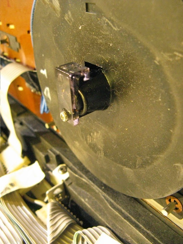
After the displays were back in the Beomaster 8000, I remembered that the volume encoder wheel had lost all its damping. The picture below shows the backside of the encoder housing (this is actually from another Beomaster, I forgot to take a pic of the assembled feature). Together with the plastic 'clamp' an O-ring seals a compartment where a viscous material can be inserted to dampen the rotation of the encoder. In the case of volume adjustment, this is desired to avoid any accidental 'dial-up' of the volume by the inertia of the fairly heavy metal wheel (think having a party with many happy people interested in your Beomaster...;-).
After the displays were back in the Beomaster 8000, I remembered that the volume encoder wheel had lost all its damping. The picture below shows the backside of the encoder housing (this is actually from another Beomaster, I forgot to take a pic of the assembled feature). Together with the plastic 'clamp' an O-ring seals a compartment where a viscous material can be inserted to dampen the rotation of the encoder. In the case of volume adjustment, this is desired to avoid any accidental 'dial-up' of the volume by the inertia of the fairly heavy metal wheel (think having a party with many happy people interested in your Beomaster...;-).
.jpg)
Geoff at Beoworld.org recently told me that he fixed the damping by putting in some high viscosity grease into the compartment, which worked great. So, I put in Silicone grease (which is the least problematic grease in terms of 'interaction with other materials', i.e. one can expect it to be inert in most settings). Here is a pic:

I also needed to replace the O-Ring. I used a Buna Nitrile 1/2"ID X 5/8"OD X 1/16"CS ring from theoringstore.com, which seemed to have about the dimensions of the old deformed ring.
This procedure resulted in a fairly well damped encoder.
Time to put the Beomaster back together!
Beomaster 8000: Display Restoration with SMD LEDs - Reassembling the Display Units
The SMD LEDs that I put into the Beomaster 8000 displays survived the 48 hrs test without problems. Time to put the display units back together. I applied the method I outlined earlier in this blog:
http://beolover.blogspot.com/2012/09/beomaster-8000-display-repair-hopefully.html
After I glued the transparency foil pieces to the back of the displays, I fixed them with carpenter clamps:

And after extracting them from the clamps:

Then I replaced R14 and R16 with 3.3kOhm and 1.5kOhm resistors to adjust the display voltage to reduce the intensity of the LEDs. See this blog entry for details about the adjustment procedure:
http://beolover.blogspot.com/2012/05/beomaster-8000-display-brightness.html
Then it was time to solder the displays back in. The insertion of the displays back into the board is tricky since one needs to line up all the pins at once...patience and calm music pays here...;-). Here is the display board after installation:

I adjusted trimmer R15 to get about 3.1V keyboard strobe (yellow) and about 4V on the LED rail (blue). It is important that the keyboard strobe does not go below 2.7V (see above blog entry for a discussion):

Looks like we are almost done. The last step before I put it back together is to check on the processor board.
http://beolover.blogspot.com/2012/09/beomaster-8000-display-repair-hopefully.html
After I glued the transparency foil pieces to the back of the displays, I fixed them with carpenter clamps:
And after extracting them from the clamps:
Then I replaced R14 and R16 with 3.3kOhm and 1.5kOhm resistors to adjust the display voltage to reduce the intensity of the LEDs. See this blog entry for details about the adjustment procedure:
http://beolover.blogspot.com/2012/05/beomaster-8000-display-brightness.html
Then it was time to solder the displays back in. The insertion of the displays back into the board is tricky since one needs to line up all the pins at once...patience and calm music pays here...;-). Here is the display board after installation:
I adjusted trimmer R15 to get about 3.1V keyboard strobe (yellow) and about 4V on the LED rail (blue). It is important that the keyboard strobe does not go below 2.7V (see above blog entry for a discussion):
Looks like we are almost done. The last step before I put it back together is to check on the processor board.
Tuesday, September 2, 2014
Beomaster 8000: Rebuilding the Displays with SMD LEDs
I saved the final restoration task until the end. The Beomaster 8000 displays are one of the major trouble spots, and this Beomaster needs to survive a long journey to Australia. So we decided to rebuild all four display units with surface mount (SMD) LEDs to ensure that the displays will still work post-shipping.
As usual I took out the display board for easier access to the solder points of the displays:

It is advised to use a desolder gun for taking the displays out, since all display pins need to be loose before removal of the displays. Trying to do this with copper braid is not advised. So I took my trusted Hakko 808 to it and removed the displays:

Then I removed them from their plastic alignment supports:

And opened them up. this is done by cutting off the plastic tabs protruding out of the bottom of the circuit boards with a sharp knife (take care to not damage the traces...):

The next steps were to scratch off the old LEDs (here also caution is advised to not damage the traces). And then, after a thorough cleaning with ethanol it was time to solder the SMD LEDs on:


It is imperative that the LEDs are well-centered on the pads that the white reflector masks can fit on without straining the LEDs and without gaps between the masks and the circuit boards (otherwise, light will penetrate from below into adjacent, potentially off segments and make them light up partially...an ugly effect).
After I completed the job I set the displays up for testing on a breadboard. I usually run them for 48 hrs before putting the displays back together. I also test them for stability by trying to wiggle them with a toothpick left and right to see if the solder joints are good. One of the issues when soldering the LEDs is that the boards do not have a solder mask, hence the solder tends to flow away from the components, which can cause problems. This can be counteracted somewhat by heating the part first, then the pad, but nonetheless, this must be kept in mind during this procedure.

So far so good! I'll be back in a couple of days and let you know how this test went...
As usual I took out the display board for easier access to the solder points of the displays:
It is advised to use a desolder gun for taking the displays out, since all display pins need to be loose before removal of the displays. Trying to do this with copper braid is not advised. So I took my trusted Hakko 808 to it and removed the displays:
Then I removed them from their plastic alignment supports:
And opened them up. this is done by cutting off the plastic tabs protruding out of the bottom of the circuit boards with a sharp knife (take care to not damage the traces...):
The next steps were to scratch off the old LEDs (here also caution is advised to not damage the traces). And then, after a thorough cleaning with ethanol it was time to solder the SMD LEDs on:
It is imperative that the LEDs are well-centered on the pads that the white reflector masks can fit on without straining the LEDs and without gaps between the masks and the circuit boards (otherwise, light will penetrate from below into adjacent, potentially off segments and make them light up partially...an ugly effect).
After I completed the job I set the displays up for testing on a breadboard. I usually run them for 48 hrs before putting the displays back together. I also test them for stability by trying to wiggle them with a toothpick left and right to see if the solder joints are good. One of the issues when soldering the LEDs is that the boards do not have a solder mask, hence the solder tends to flow away from the components, which can cause problems. This can be counteracted somewhat by heating the part first, then the pad, but nonetheless, this must be kept in mind during this procedure.
So far so good! I'll be back in a couple of days and let you know how this test went...
Monday, September 1, 2014
Beomaster 8000: Replacing Indicator Light Bulbs With LEDs
I moved on to rebuild the display board of the Beomaster 8000. One of the four indicator light bulbs was broken. It is difficult to find appropriate bulbs these days, so we decided to replace all four indicators with LEDs to get this Beomaster ready for its big journey to Australia. LEDs are much more resistant to vibration and shock that can occur during transit.
Since LEDs have a much more directed emissions profile than light bulbs, it takes two LEDs to replace the light bulbs. I used generic 15 mCD, 2 V, 20 mA red LEDs made my Multicomp (Newark 14N9416). Two of them just generate about the same light output as one of the 80mA 6V bulbs that are originally used. Since the bulbs run at 5V, the two 2V LEDs needed a current limiting resistor to get them to run at 20mA. I used 47 Ohm 1/2 W resistors, which is what I had in stock. Smaller 1/4W ones would be o.k., too. Note that one needs to remove resistors R34, 36, 38, and 40 on board 8 to ensure that the LEDs turn off properly. Another interesting question was whether the Clipping indicator would still work properly after this procedure.
I made a short video about the entire project where all aspects are discussed. Enjoy:
On to the LED displays!
Saturday, August 30, 2014
Beomaster 8000: Replacement of Speaker Switches - Laser Cut Plexiglass Switch Adapters
I always replace the speaker switches when I restore a Beomaster 8000. They are often corroded, and I experienced several failures in my own Beomasters (I often use my Sennheiser RS180s, and therefore need to switch the speakers on and off fairly frequently...). The issue with these switches is that the original model was designed with a high density board base, which had installation guide tabs on the side. The Beomaster housing is designed with bays that fit these tabs exactly. All new switches seem to be fully enclosed in plastic. While the general form factor is still available, in the past I had to extract the high density boards from the old switches, modify them with a Dremel, and then glue them to the bottom of the new switches. See this post for the original procedure:


I never really liked the Dremel job...not precise enough for my taste. Recently, I learned to operate a laser cutter. What better first project than designing a nice adapter plate, which would align the new switches precisely to their compartments??
I cut the adapter platelets from 5/64 plexiglass (this is a bit too thick, but that is all I had at that point). That meant I still had to put the Dremel to them to reduce the thickness of the tab areas to about 3/64, the thickness of the high density board. If I do it again, I will cut the entire adapter board from 3/64 plexi or something similar. This shows the new switches in comparison with one of the old ones and the laser cut adapters. Note the slits, the board mounting guides of the switches fit snugly into them, aligning the switch (BTW: I used No.: 611-S201031MS02Q from Mouser) with the adapters.
Here after glueing the adapters to the switches and Dremeling the tabs thinner:
Here are a few pictures from the installation process:
Original switches removed from their compartments for desoldering:
New switches installed (it surprised me how durable the plexiglass was during soldering...no issues with melting, warping etc...):
In their compartments:
And with heat sink cover installed:
Perfect!! These new switches are much smoother than the old ones and are guaranteed for a few million switchings! On to the display board!
Beomaster 8000: Replacing the Main Reservoir Capacitors - 3D Printed Adapters for Smaller Modern Capacitor Sizes
Today I received the new reservoir capacitors for my current Beomaster 8000 restoration. We decided not to use the Mundorf capacitors (there were out of spec and are going back to the manufacturer) and instead settled for Made in Japan quality 105C power supply capacitors made by Nippon United Chemi-Con (EKMH630VSN103MA50M). My BK Precision 879B clocked them all at 9200uF and 13 mOhm ESR, well within spec. Actually, this ESR value is remarkably low. The data sheet states 22 mOhm.
Unfortunately, it does seem increasingly difficult to get newly made 10000uF capacitors with the 80 mm x 40 mm form factor of the original capacitors in the Beomaster. The Chemi-Con models measure only 50 mm x 35 mm.
Hence, I decided to design 3D printed adapters that would give them the old form factor. This worked quite well. The adapters were printed with a Makerbot II using black PLA filament. I achieved nice a press-fit, which united the capacitors with the adapters in an almost inseparable way. Here is a picture in comparison with one of the old caps from the Beomaster:

I will post the STL file for the adapters on beolover.com.
The exchange was uneventful. Here are some pictures:
Right channel before:

Right channel after:

Left channel before:

Left channel after:

After the exchange I fired the Beomaster up, and all was well. On to the speaker switches while we are back in there!
Wednesday, August 27, 2014
Beomaster 8000: FM Tuner Recap
Today was FM tuner day! While I am waiting for the new reservoir caps for the current Beomaster 8000 restoration, I decided to do the tuner today. (More about the capacitors later...the Mundorfs were not really as golden on the inside as the Made in Germany label would suggest). The tuner recap was an uneventful activity. Some calm music on my Beosound 9000, and off I went. Here are the pics:
Before:

And after recapping with quality 105C caps and cleaning of the contacts. As usual they were oxidized and needed the fiberglass brush and a coat of DeoxIT D100L:

And a detail:

After plugging the boards back in, I turned the Beomaster on, and everything was happy!
Tuesday, August 26, 2014
Beomaster 8000: Replacement of a Broken Signal Strength Meter
Ok! Beolover is back in town! I found a very welcome package in the container with the held mail that was delivered by the US postal service yesterday upon my return. This package contained a great-condition signal strength meter for the Beomaster 8000 that I am currently restoring. While I was gone Martin ('Dillen' on the vintage forum at Beoworld.org) sent me this part! As usual, when things get tough on The Bench he was able to help! Thank you very much!
So I set out to put the meter in. Before inserting it, I tried to characterize it a bit for future reference. It seems to be a simple 150mV panel voltmeter with a resistance of 750 Ohm. Its dimensions are 45 mm x 48 mm. There are still some Chinese manufacturers that churn out voltmeters with this form factor. I am thinking one might be able to buy a generic mechanism and put the glass cover of the broken B&O meter on it to make it fit into the control panel cover.
If you look at the circuit diagram, the 750 Ohm create a voltage divider with resistor 2R21 (12k), which imparts an approximate division by 16 to the applied voltage from the IF section, i.e. a good station produces about 2V at the voltage divider, which translates into 125 mV at the meter, yielding a reading of about 7-8.
After doing these measurements, I put it in. I made a short Beolover video about this process. Enjoy:
It seems this went well...on to the remaining restoration tasks.
Thursday, August 7, 2014
Beomaster 8000: Recapping the Preamplifier Board (PCB #3)
Today I did the preamplifier board of my current Beomaster 8000 restoration project. I am still waiting on the 3D printed capacitor adapters for the Mundorfs, which I need to complete the power supply. The recap of the preamp went uneventfully. Everything still working after plugging everything back together...a good sign...;-). Here are the pics:
Before:
+Before.jpg)
After:
+After+III.jpg)
On to the tuner boards.
Before:
After:
On to the tuner boards.
Wednesday, August 6, 2014
Beomaster 8000: Recapping the Filter and Tone Controls Board (#4) and Broken Signal Meter
I moved on to recap the filter and tone controls board (PCB #4) that is under the control panel of the Beomaster 8000 I am working on...not much to report about the capacitor replacement. Here are pics:
Before:

and after:

Sadly, the more 'interesting' part of this board is the non-working signal strength meter. I unsoldered the contacts and measured the resistance. It is open circuit, i.e something is wrong on the inside. It looks pristine inside, from what I can tell by peeking through the plexiglass cover. I am wondering if one can open it up without penalty...I guess, we will find out soon.
Beomaster 8000: Mundorfs are in the House!!
Today a set of four Mundorf 10000 uF "M-Lytic AG" arrived at my doorstep via Parts Connexion, a Canadian supplier of audio components. Per customer request I will install these in the currently benched Beomaster 8000. Pretty:

But small!! In the background is one of the original caps. I am currently designing 3D printable supports for these small 30 mm x 50 mm packages to fit them into the cavernous Beomaster capacitor bays. I hope to get them printed in the next couple days.
Sunday, August 3, 2014
Beomaster 8000: Power Supply Rebuild
Today I went on to rebuild the power supply board (#6) of the current Beomaster 8000.
Here is a picture before replacing the electrolytic caps:

The big yellow cans often are out of spec at this age. In this Beomaster, however, they showed reasonable ESR and capacitance values....nonetheless out they went with all the other electrolytics. Here is a pic after putting in quality 105C caps:
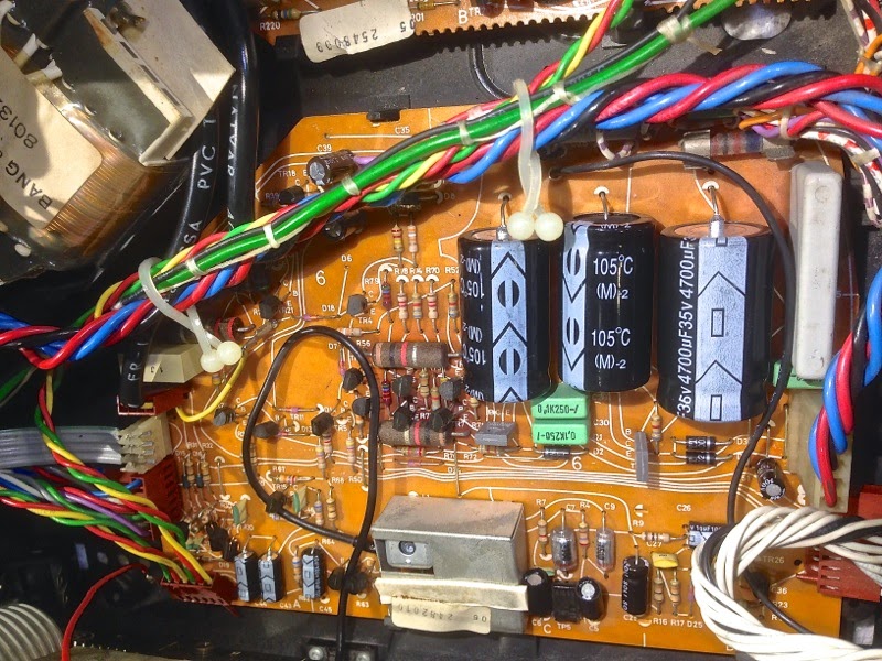
I cleaned all the headers on the board and coated them with DeoxIT D100. Then I plugged everything back together, and the Beomaster came on without fuss. I hope the Mundorfs will soon arrive that I can replace the main reservoir caps to put this Beomaster fully on a solid footing.
Saturday, August 2, 2014
Beomaster 8000: Restoration of the Output Amplifiers
As usual, I rebuilt and tested the output amplifiers (PCB #5) of the current Beomaster 8000 restoration project before turning it on the first time. While the ebay seller claimed it was 'fully working' there is always a chance that one of the output trimmers goes non-contact during transport, i.e. in my opinion it is worthwhile to do the outputs first and test them with external power supplies (see here for a description of the process: http://beolover.blogspot.com/2011/09/output-stages-testrecap.html).
This takes a bit longer, but definitely saves a lot of cost and effort compared to replacing the output transistors. Anyway, here are the before and after pictures...:
Left amplifier before:

after:

Right amplifier before:

after:

It was definitely a good idea to replace the caps, most were cracked. Here is a picture of one of the 220uF caps:

I measured the capacitance and ESR of these caps, and they were still all in spec...pretty amazing, considering the cracks...it seems the capacitor situation depends a lot on how the individual Beomaster was stored/treated, and whether it was used regularly etc...
When testing the boards, the external power supplies showed the following currents after adjusting to 18 mV for both boards:
+54V--> 0.10A
-54V-->0.11A
+15V-->0.01A
This all made sense, so I reconnected the output rails and fired the Beomaster up. It came on with a healthy double relay click and then showed a nicely working display. It seems all segments are working - also pretty amazing, considering the 'white PCB' style of the displays. I guess it was really treated well in its pre-eBay life!
I easily tuned into my favorite local radio station and enjoyed a bit of their NPR programming. The only issue I could find during this brief first test was a not working 'filters' light...hopefully this is just a light bulb.
On to the power supply.
Monday, July 28, 2014
Beomaster 8000: First Look Inside
It seems the last Beomaster 8000 is now happy, and I put it back together. It went to the living room for a few weeks of testing amongst his friends the Beogram 8000 and the Beocord 9000.
Time to open up the next 8000 in line! This one is very nice on the outside, and the interior is not different. While it was opened up before (slight screwdriver mark on the glass cover - still have to see an 8000 without...it is definitely a good idea to protect this corner with some tape before opening them up...). There is also an about 15 year old cap in there (6C35 to control the 5V ripple after the voltage regulator). But whoever did it put it back together properly...all screws the right sizes, nothing missing, even the small copper damper for the control panel door release is in its proper place.
Otherwise, it is as original as it gets upon visual inspection. Also very clean. Almost no dust! Very nice! Check out this left channel output board: Almost as it were recently put in a cleaning bath:

But, appropriate for the age, two of the red electrolytic caps are cracked, indicating that a full recap is probably a good idea. The output resistors are non-browned, which makes me hopeful that it really still worked as it was advertised on ebay.
The displays are unfortunately pre-solder mask style, as is evident from the whitish epoxy boards:

We will see how the segments are when I turn it on the first time. Experience tells me that this style displays is prone to segment failure. It seems that displays with the greenish epoxy boards may be more stable over time.
Next step: As usual, I will rebuild and test the output stages before the first turn on.
Time to open up the next 8000 in line! This one is very nice on the outside, and the interior is not different. While it was opened up before (slight screwdriver mark on the glass cover - still have to see an 8000 without...it is definitely a good idea to protect this corner with some tape before opening them up...). There is also an about 15 year old cap in there (6C35 to control the 5V ripple after the voltage regulator). But whoever did it put it back together properly...all screws the right sizes, nothing missing, even the small copper damper for the control panel door release is in its proper place.
Otherwise, it is as original as it gets upon visual inspection. Also very clean. Almost no dust! Very nice! Check out this left channel output board: Almost as it were recently put in a cleaning bath:
But, appropriate for the age, two of the red electrolytic caps are cracked, indicating that a full recap is probably a good idea. The output resistors are non-browned, which makes me hopeful that it really still worked as it was advertised on ebay.
The displays are unfortunately pre-solder mask style, as is evident from the whitish epoxy boards:
We will see how the segments are when I turn it on the first time. Experience tells me that this style displays is prone to segment failure. It seems that displays with the greenish epoxy boards may be more stable over time.
Next step: As usual, I will rebuild and test the output stages before the first turn on.
Friday, June 6, 2014
Beomaster 8000: A New Day A New Beomaster!
Another Beomaster 8000 just arrived. From ebay on route to Australia (yes, beolover went 'global'!...;-) it made a stop at my bench for some TLC. This was a better ebay experience. While the seller did not communicate in response to my requests for double boxing, he/she at least did a pretty solid job with a single box (and used FedEx - I am done with the post office since a recent disturbing experience where they dented the heat sink of a just repaired 8000...):

And it came with the original warranty document and an original owner's manual. Did I mention the remote? and speaker cables. Even an antenna is in the box. Very nice.
And check out the almost pristine veneer corners!:


Seems this baby comes from a home where people care about their equipment! I should keep it for myself! (just kidding!..My wife says three 8000s is enough!...;-)
Let's see what awaits us inside!
And it came with the original warranty document and an original owner's manual. Did I mention the remote? and speaker cables. Even an antenna is in the box. Very nice.
And check out the almost pristine veneer corners!:
Seems this baby comes from a home where people care about their equipment! I should keep it for myself! (just kidding!..My wife says three 8000s is enough!...;-)
Let's see what awaits us inside!
Subscribe to:
Posts (Atom)