Featured Post

Beolover SyncDrive: DC Platter Motor Replacement for Beogram 4002 and 4004 (Type 551x and 552x)

Late Beogram 4002 and the 4004 (Types 551x and 552x), which have DC platter motors instead of the earlier synchronous AC motors usually suff...

Showing posts with label 3D printing. Show all posts

Saturday, May 21, 2016

Beomaster 8000: Visit of an Old Acquaintance - Restoration of the Control Panel Lid and a Redesigned Lid Linkage Replacement Part

Oh well...Beoloving can be a bit experimental. When new parts are developed occasional failures need to be anticipated. So it was the case with the part that I designed last year to repair a control panel lid spring retainer when I restored a Beomaster 8000. This part failed during return shipment, maybe due to the package getting a bit hot and my plastic part a bit soft, which let the spring 'escape'. This is how it looked when I received this unit again about a week ago:
To finally cure this issue for good, we decided to purchase a Beomaster unit from ebay. A unit with a badly damaged heat sink became available:
Seems a fork lift drove through it or a similar disaster happened. Miraculously the control panel lid was still intact without any damages. While convenient for the issue at hand, it always hurts to see a Beomaster 8000 go down like this due to carelessness or poor packing for shipment.

Some more parts from this unit turned out to be useful to cure some more cosmetic issues with this unit like the scratched 'Monitor' button
and the broken off control panel lid lock that I replaced with a 3D printed part last year. I took the opportunity to replace both with original parts from the ebay unit:

Beautiful again!

When I put the unit back together after these repairs, it occurred to me that the lid made an ungainly clonking noise when opening. It turned out that the control panel lid linkage that connects it to the motion damper was shifting abruptly from one side to the other in the fixture that connects it to the lid during the opening sequence. I took this as an invitation to improve my 3D printed replacement linkage by making the upper end a bit thicker, so that it fits precisely into the allotted gap, preventing the shifting issue:
I installed it (shown a prototype printed in red for more detail):
After verifying that this cured the issue I replaced it with a black 'production' part since the upper end can be seen when the control panel lid is open:
This linkage, like all my parts, is available to other enthusiasts. Just send me an email or use the contact form on the sidebar.  There is also a video on my YouTube Beomaster 8000 playlist that demonstrates the installation of the linkage.

All good now in the control panel section of this Beomaster! Time for a little test-drive before shipping it back!




Saturday, December 5, 2015

Beogram 4002 (5521): Replacing the Tracking Sensor Light Bulb with a SMD LED

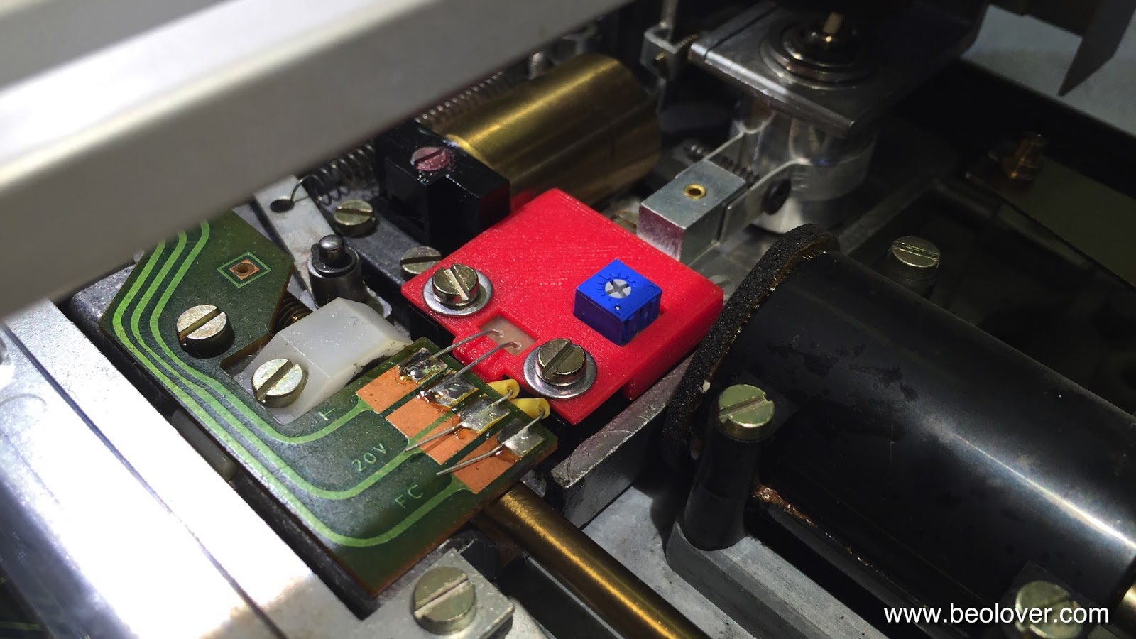
The Beogram 4002 that is on my bench right now came with a broken tracking sensor light bulb. I replaced the bulb housing assembly with my SMD LED based drop-in ready replacement part. This unit was recently redesigned on the occasion of a Beogram 4000 restoration to feature an integrated intensity trimmer, which makes the adjustment of the tracking sensor feedback much more straight forward. The trimmer allows to fine-tune the feedback after the mechanical positioning of the light sensors below the light source. The adjustment process is discussed in detail in this video. 

This shows the original setup of the tracking sensor:


Here is a picture of the latest iteration of my design in comparison with the original bulb assembly after I removed it from the tracking sensor:

This part is available to other B&O enthusiasts. Just send me an email.

This shows the installed part:

Once the LED assembly was soldered in, I performed the adjustment procedure as shown in my video to achieve that the carriage motor starts advancing after 2±1 rotations of the record after lowering the needle onto the record. This restored the basic functionality of this Beogram. On to replacing the RPM light bulbs with LED assemblies.


Wednesday, November 25, 2015

MMC20 Cartridge Mount Replacement: Gold Plating of Contacts

I had some fun last night with learning how to coat the contacts of my MMC20 mount reproduction part with gold. This is a follow up to this post. I think naked copper traces are not good enough for long term stability on this part due to oxidation issues. I used an electroplating solution soaked wand and 4.5V DC with the negative lead connected to the traces to be coated (metal ions are positive) and the positive to the wand. After a few minutes working the wand I saw a golden sheen on the copper...this picture shows the coated traces in comparison with some uncoated ones:

After this success I studied up a bit more about gold plating and it seems that the microelectronics industry standard is to put a nickel diffusion barrier between the gold and the copper...I guess I need to get some Ni electrolyte going. I also need to test for adhesion, there are some interesting test procedures for meeting the electronics industry standards. But I guess I am one step closer to the final design!

Monday, November 23, 2015

MMC20 Cartridge Mount Replacement: Third Design Iteration

This is a follow-up to my initial posts about the design of a MMC20 cartridge mount replacement. The first design iteration is discussed here and the second one here. The result of the second iteration was pretty close as in that I was able to stick a cartridge on it and that the base fit into the arm tube of a Beogram 400x. The issues with V2 were that the angle at which the cartridge mounted was about 4 degree off and that the cartridge was a bit loose. Furthermore, the nylon based print was too flexible. 

Version 3 shown here uses a different, stiffer material and I changed the geometry a bit to ensure proper mounting angle and a tighter cartridge fit. Here are a few impressions:

The mount now fits with a decent press fit into the arm tube (I did have to sand it slightly - a concession to the still imperfect printing tolerances at Shapeways). It also looks fairly original, although the material is a bit rough in difference to the original injection molded plastic:

The good thing is that the tab is invisible once the cartridge is mounted. Here is a picture of the fit:

Quite prefect now, I would say...After I stuck the cartridge on I measured the coil resistances while wiggling the mount a bit. It seems the contacts between mount and cartridge are now stable!
To get this ready for prime time, however, I still need to learn to gold-plate the Cu strips. Another point is to find a more perfect way for glueing the contacts PCB. Beolove springs from continuous improvement! But I am fairly positive now that this design is getting pretty close for some in-situ testing.


Thursday, September 17, 2015

MMC20 Cartridge Mount Replacement: Second Design Iteration

This is a follow-up to my initial post about the design of a MMC20 cartridge mount replacement. In the meantime, I acquired a Beogram 4000 with a broken off mount, so now this is 'personal'...;-). Ouch!:

I just received the redesigned Version 2 prints from Shapeways. The main issue with the initial version was that the back part would not fit on the lower part of the original mount that will be reused, and that the contact tab would make intermittent contact. I realized that the issue was the 'bump' that I designed into the tab to press the contacts into the cartridge contacts. One I looked at the broken off tab of my Beogram 4000, I saw that a simple straight shape should work. So version two of my design aspires to closely resemble the 4000 version of it.

Here are a few impressions. Along with the changed shape, I also needed to redesign the tool bodies that are used for pressing the circuit board into the mount while the glue dries:

Hers is a picture of the curing process:


And here the result in comparison with the original mount (this one is from a later Beogram and was supplied by Sonavor (Beoworld)):
Then I tested it on a MMC20S cartridge. It made good Ohmic contact and I measured the usual 770 Ohms per coil:

This iteration now fits very well on the lower (original) part of the assembly:

Consequently, the part also fits into the arm tube:

However, the mounting angle is a bit too steep. From the gap, using a protractor, I deduced that I need to reduce the angle by about 4 degrees. Oh well, back to Autodesk Inventor for Version 3.  While I will be waiting for the Version 3 prints I also need to figure out how to plate the PCB traces with gold to ensure long term stability. We do not want to have oxide layers getting in-between our precious vinyls and our ears...;-)
Designing a new part: Quite a laborious process - A resuscitated Beogram 4000: Priceless! This is Beolove!


Sunday, August 23, 2015

MMC20 Cartridge Mount Replacement: First Design Iteration

A while back Sonavor posted some shocking pictures on his thread about Beogram 400x repair and restoration on Beoworld.org. He was about to finish his restoration of a beautiful Beogram 4000 and after having had to meet challenges like replacing the line transformer and the strobe lamp, the gods of vintage hifi gave him one last challenge: When he tried the deck out, the cartridge mount broke off, probably due the previous owner having cracked the small plastic tab that inserts the electrical connections into the cartridge body and also holds it in place. A typical B&O design: Very elegant but needs a refined touch to use it properly. Here are two of Sonavor's pictures after he extracted the broken cartridge mount after dipping the extracted arm into hot water for a while to loosen up the glue:


Absolutely nothing one wants to encounter while working on such a beautiful design! He was able to fix it by extracting a mount from a lesser model, but we started wondering if these mounts can be reproduced with modern 3D printing technology. Obviously the contacts are the biggest challenge. It is interesting to see that in the 4000 they were formed by a flex circuit board that was integrated into the plastic part. In more recent models the contacts were actual Au coated Cu-Be tabs held in place with a plastic bar (see below).

Sonavor then sent me a spare tonearm with a loose mount giving me an opportunity to have a closer look (I was reluctant to extract the mount from one of my working turntables, as you can probably understand...;-). So I set out to build a replacement part. The first step was to make a model of the plastic part in CAD software and have it printed. I did that and yesterday I finally received the first iteration of this design from Shapeways. This shows the part (blue) in comparison with the original part that holds the cartridge:


I decided to go the 4000-way for the contacts using the flex PCB approach. This required to glue the board in place to the plastic part, which has a 5 mil recess to accommodate the board thickness (visible in the picture if you look closely). To achieve a good bond I designed a tool matching the shape of the PCB area. This allowed me to apply pressure to all parts of the PCB during the curing process:


I made a flex PCB with traces with the right pitch. The traces are 1 mm wide and spaced by gaps of 0.7 mm, i.e. the pitch is 1.7 mm. Here is a photo of the final board in comparison with the contacts on the mount:


Then I cut one of the strips to shape and coated the traces with solder. In the final version this will hopefully be an Au coating:

The next step was glueing it to the mount. I used standard epoxy. Superglue would probably be another option. My thinking was that epoxy is a bit flexible, giving this PCB a bit of leeway when someone sticks on a cartridge:
After 10 min holding the assembly (I will definitely design a second tool for the backside of the mount for the next iteration that I can use a carpenter clamp for that...;-) and cutting the traces to length the PCB was attached:


And assembled with the lower part of the assembly that features the grounding pin:


And here with cartridge :

For comparison here is a photo of the original part. A quite nice match!:

I evaluated the conductivity across the contacts. For both original and new part I measured a nice 770 Ohm across each of the coils, so that is pretty promising.

What was not promising that much was that the contact was a bit intermittent on one of the coils. This means I need to redesign the shape of the bump a bit that presses the contacts into the contacts on the cartridge. Also my parts was a tad to thick on the back end (3D printing is not an exact science (yet) and achieving a perfect fit is usually a trial and error effort needing a few iterations), and I had trouble sticking it into the arm all the way. I think I could force it in, but then that would not be Beolove!..;-):
After these tests, I replaced the cartridge a few times and after about 20 cycles one of the traces came off...this can probably be addressed by recessing the PCB at the tip of the mount to reduce the forces on the traces at the end of the board during the insertion process. On to the next design cycle.


Tuesday, March 31, 2015

Beogram 4002 (5513): Cabinet Repair and Guiding Washers Installation

While I was waiting for the pseudo balanced 'audiophile' RCA cables from Sounds Heavenly, I gave the cabinet of the Beogram 4002 (5513) some TLC. The cabinet was cracked on both corners, and all the guiding washers that hold in place and enable its sliding action were missing. Here is a picture of one of the corners:

It is easy to glue them back together since the cabinet is held together by metal bands. So all one has to do is to put some glue on the wood surfaces and hold it together with carpenter clamps until the glue is dry:


Much more beautiful after glueing the cabinet back together:


This picture already shows one of the new 3D printed guiding washers installed (this one is under the key pad). They enable the cabinet to slide on a precisely defined path (as demonstrated in my YouTube video about the washers). So if you have a 'wiggling' cabinet, then it is time to check if these washers are still there. They were originally made from a flimsy plastic that cracks and degrades over time (B&O realized that soon, and the 4004 models have metal reproductions of them...but the 4002s have usually the (missing) plastic ones. Here is a picture of the replacements. One needs five of them:

Here are the four other locations where I installed them on this Beogram:


Not much left to do except implanting the RCA cables and glueing the two side-tabs of the keypad back down (one can see one of them sticking up a bit on the picture above left of the 'START' label). A Beogram 4002 well on its way to a full recovery!


Saturday, March 7, 2015

Beomaster 8000: 3D Printed Control Panel Door Lock

The final challenge of my current Beomaster 8000 restoration project was to restore full functionality of the control panel cover. When I received the unit, the aluminum cover had lost its spring action, i.e. it would just loosely sit on top of the control panel by means of gravitational forces. In pristine condition, the panel is held down by the plastic lock which fits into a small cutout in the side of the aluminum panel. When pressing 'programming' on the bar between the cover and the lower body of the receiver, the lock releases the panel and it opens at a measured speed, controlled by a motion damper situated below the control panel to which it connects via a acrylic linkage.

In the present unit, the control panel cover lock was mutilated by Mr. Amateur for a reason only known to himself, i.e. it was not able anymore to hold the cover down. He cut off both ends of the small plastic part. Here is a picture of the sad condition of the lock as I found it:


So, the first step towards restoring the full functionality of the cover mechanism was to reproduce the lock part via 3D printing. For this I extracted a pristine lock from one of my three Beomaster 8000s and took measurements. Then I had it 3D printed on a Stratsys uPrint. Here is a photo of the printed part in comparison with the mutilated original:


This video discusses the process of replacing the lock:


Unfortunately, Mr. Amateur also disabled the spring mechanism of the cover so it would not open up with the mutilated lock not holding it down anymore. To 'achieve' this he removed the metal plate that holds the spring in place in the back of the aluminum cover part, which released the spring and let the cover fall down freely. This is shown here (the wire loop that sticks out needs to be secured within the plastic body of the panel underpinnings to generate the spring force):


Since the original metal plate was lost, I cut a new metal insert from a piece of galvanized steel sheet, and pressed it into the slot. This reactivated the spring mechanism, and the cover would open again by itself when released from the lock:


The next step was to restore the damping mechanism. Mr. Amateur disconnected the linkage from the damper at some point and then must have tried to reconnect it, but he did not understand how to reinsert the lower end of the linkage into the arm of the damper (just put the damper arm vertical, and slide the linkage from the right side over it - the gap fits the protrusion on the arm in that position...live and learn...;-). So he opened the gap in the linkage (apparently by slightly melting the linkage over a flame or similar) in an attempt to stick the linkage back on the arm, but this resulted in a situation where the linkage slipped off the damper arm by itself due to the enlarged gap whenever the cover is closed. I fixed this by exchanging the damaged linkage with a 3D printed replacement, which I designed a few months ago for another Beomaster 8000 restoration where the lower part of the linkage was broken off (see here for a description of this effort). Here is a photo of the 3D printed replacement in comparison with the damaged original:

And here installed on the cover:


The action of the restored control panel cover is shown at the end of the above video. Now this Beomaster 8000 will be tested embedded in my Beosystem 8000 in its fully restored glory for a couple weeks under 'real life conditions' before it goes back to its owner (to make sure that there are no loose ends under the hood - these complex units tend to have intermittent issues, that often only manifest themselves after a using them for a while)


Wednesday, January 21, 2015

Beomaster 8000: Volume Wheel (Encoder) Damping - 3D Printed Paddle Wheel

This is a follow up to my last blog entry about restoring the damping of the Beomaster 8000 volume wheel rotation. Often, the volume encoder looses all its damping over time, which can create an unpleasant situation when someone uninitiated to the issue accidentally cranks up the volume to 6.0 because the volume wheel does not stop spinning.
My latest solution involves a 3D printed 'paddle wheel' that press-fits on the volume encoder shaft. Together with a more heavy duty high viscosity damping grease, the Nyogel 767A a very smooth purely viscous damping effect can be achieved. I made a short video about the new part and its installation:


Here is a better picture of the part (printed with a Form 1 stereolithography printer):


Wednesday, December 10, 2014

Beogram 4002/4004: Replacement of the Transport Lock Bushings With 3D Printed Parts

I recently got into 3D printing with stereo lithography. This proved a valuable skill for replacing the decayed rubber bushings in the transport locks of my Beogram 4002. Here is a picture of how I found these bushings upon opening the Beogram up:


Clearly the rubber had seen better times. So I removed the fragments and designed a two-part replacement solution with Autodesk Inventor that could be conveniently installed without having to extract the floating turntable chassis. I printed the parts with a Form 1 stereo lithography (SLA) 3D printer, which produces relatively soft and pliable parts, ideal for the task of dampening impact during transport of a precious Beogram! Here is the result of my labor:


The 10-15 micron resolution of these SLA printers is much superior to filament based printers (~100 microns), i.e. it is a much better technology for small parts that need to have an exact fit. In this case, the fit needed to be pretty good to be able to generate a press-fit, that would hold both halves of the bushing in the opening in the chassis. This worked very nicely as you can see in this video, where I demonstrate the installation. Enjoy!: