Featured Post

Beolover SyncDrive: DC Platter Motor Replacement for Beogram 4002 and 4004 (Type 551x and 552x)

Late Beogram 4002 and the 4004 (Types 551x and 552x), which have DC platter motors instead of the earlier synchronous AC motors usually suff...

Showing posts with label incandescent. Show all posts

Saturday, December 5, 2015

Beogram 4002 (5521): Replacing the RPM Scale Illumination Bulbs with SMD LEDs

After replacing the broken light source of the tracking sensor, The next step of my current Beogram 4002 (5521) restoration was to replace the incandescent light bulbs in the RPM trimmer panel. The 33 RPM bulb was burned out, so we decided to replace both bulbs with my drop-in SMD LED assemblies. I am using red-green LEDs to ensure that there is a red light component to ensure proper illumination of the red RPM indicators. While amber LEDs can result in an incandescent-like look, they are not able to properly illuminate red surfaces due to their narrow wavelength distribution. Here is a picture of the small circuit boards that carry the LEDs as well as two current limiting resistors, one for the red and one for the green LEDs. This allows to tune the relative intensities to achieve an authentic looking illumination:

I recently made a video that shows how to exchange the bulbs with these boards. They are available to other enthusiasts. Just send me an email. 

Here are a few impressions of the installation in this particular Beogram. This shows the trimmer panel after removal:
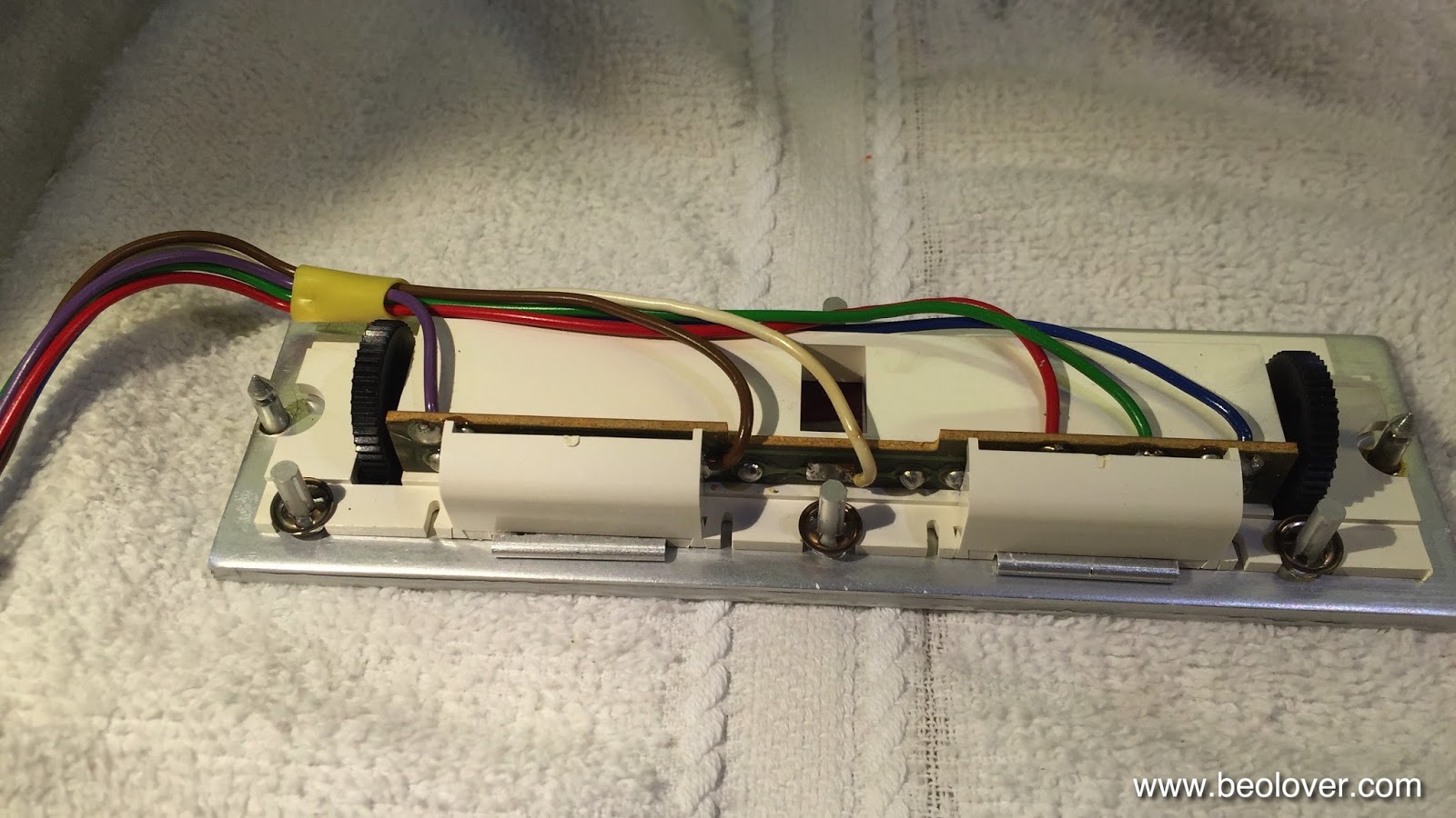
The bulbs can be accessed after removing the two covers:

After unsoldering the leads the bulb assemblies can be slid out:

Now the PCBs can be installed. It is important that they sit flush with the aluminum surface:

And then the covers can be replaced:

And that is it!


Beogram 4002 (5521): Replacing the Tracking Sensor Light Bulb with a SMD LED

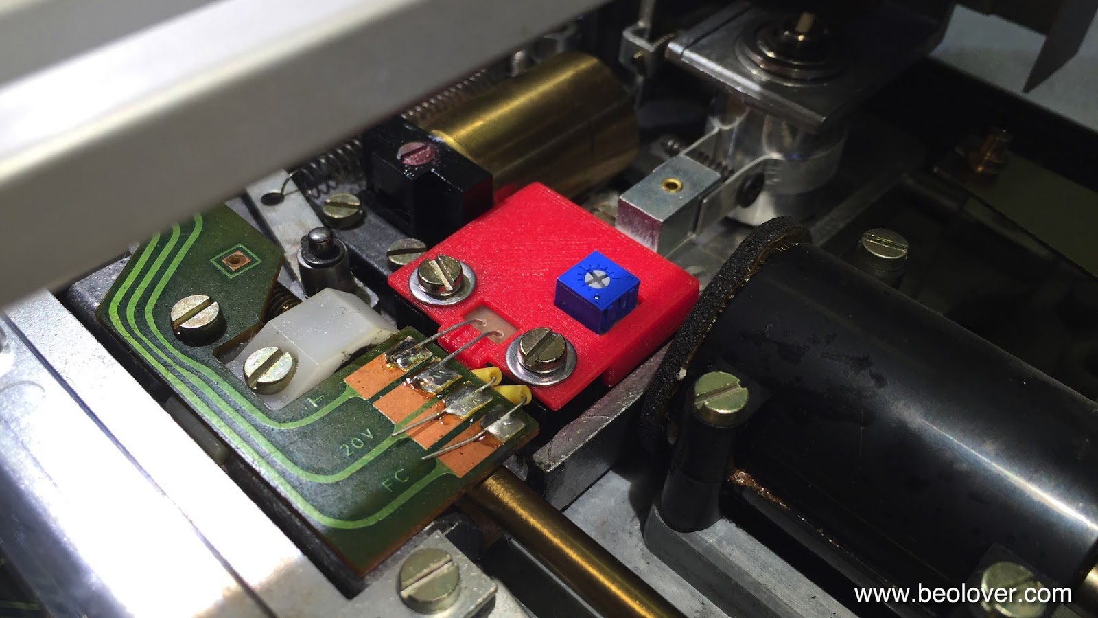
The Beogram 4002 that is on my bench right now came with a broken tracking sensor light bulb. I replaced the bulb housing assembly with my SMD LED based drop-in ready replacement part. This unit was recently redesigned on the occasion of a Beogram 4000 restoration to feature an integrated intensity trimmer, which makes the adjustment of the tracking sensor feedback much more straight forward. The trimmer allows to fine-tune the feedback after the mechanical positioning of the light sensors below the light source. The adjustment process is discussed in detail in this video. 

This shows the original setup of the tracking sensor:


Here is a picture of the latest iteration of my design in comparison with the original bulb assembly after I removed it from the tracking sensor:

This part is available to other B&O enthusiasts. Just send me an email.

This shows the installed part:

Once the LED assembly was soldered in, I performed the adjustment procedure as shown in my video to achieve that the carriage motor starts advancing after 2±1 rotations of the record after lowering the needle onto the record. This restored the basic functionality of this Beogram. On to replacing the RPM light bulbs with LED assemblies.


Wednesday, October 28, 2015

Beomaster 8000: Replacing the Incandescent Indicator Light Bulbs with SMD LEDs

I always enjoy rebuilding the display board of Beomaster 8000s. So much of the signature looks of these units depends on the gorgeous large 7-segment displays and the masked indicator lights for clipping, filters, mono and manual tuning. With this particular unit I started out by replacing the indicator bulbs with my recently designed SMD LED based replacement boards. There are two versions of this board accommodating the two left and right incandescent bulb cabinets. The contact pads for the bulbs are mirrored in these compartments, while the polarity remains the same. This mirror symmetry requires different boards to accommodate polar devices like LEDs. Here is a picture of the boards that I installed:

When I developed these boards I made a video how to install them:

It is important to keep in mind that the LED boards run on a much smaller current than the light bulbs, and this requires the removal of the resistors R34/36/38 and 40 on the display board. Otherwise the LEDs will always be on.

This shows the original light bulbs in their cabinets:

And after replacement with the SMD LED boards:

And in on condition:

On to rebuilding the 7-segment displays.


Monday, September 21, 2015

Beogram 4002: Replacing the RPM Indicator Bulbs with SMD LEDs

I continued working my way through replacing the lightbulbs in the Beogram 4002 (5513) that I am restoring right now. Today was RPM indicator day. I took this as an opportunity to further improve my LED replacement approach. In an earlier post I described how to replace the incandescent bulbs with the red and green LEDs of a RGB through hole 5 mm LED. This worked fairly well, but I was not 100% happy with the homogeneity of the back illumination of the RPM trimmer scales. The issue with standard through hole LEDs is their directed emission pattern out of the top of the LEDs. This made it necessary to sand their bulbs into a matte surface and also painting the tops black to prevent a too high emission on one side of the trimmer scales. 
My latest approach is based on my current approach to implanting LEDs for the position scale illumination of Beogram 4000s. I changed the PCB shape to fit behind the bulb covers of the 4002 bulb housings, and I adapted the current limiting resistors (10k for green and 2.5k for red) to the 21V operating voltage and the different illumination angle of the diffusing cavity. I made a short video about this updated approach:


Sunday, July 19, 2015

Beocord 9000: Replacing the Incandescent Indicator Light Bulbs with SMD LEDs

Two of the indicator lights of the Beocord 9000 that I am currently restoring had issues. One had a broken off lead (REC CAL), which seems to be the standard failure mode of these bulbs, and the other (TIME CAL) had low intensity due to a partially evaporated filament.
I decided to replace these bulbs with SMD LEDs matching my current approach with these light in Beomaster 8000 units. This achieves long term stability and also makes the displays resistant against shipping damage. Unfortunately, the reflector cabinets of the Beocord 9000 are smaller than the ones in the Beomaster 8000, so I had to redesign my PCBs for the SMD LEDs. I made a short video about the process:


Here are a few additional pictures:

One of the bulbs (RECORD) has a different lead polarity than the other three. This needs to be taken into account for the LED replacements since LEDs are polar:

These are the circuit boards that I designed. I use high brightness white LEDs that I run with 1k resistors (1.2k achieves the original low brightness of the incandescent bulbs). We decided to go with a bit higher light output for the counter 7-segment displays, and so I matched the indicators. It looks much nicer this way if the room is lit or the sun strikes the unit, while it still does not 'bite' the eye if the room is dark.

This shows them in action without and with covers:


And here with the cover installed:


Thursday, December 4, 2014

Beogram 4002/4004: Speed Selector Circuit and Replacement of Its Incandescent Light Bulbs with LEDs

The last incandescent light bulbs are now gone in my Beogram 4002. I decided to completely replace all light bulbs since I like the longterm stability of LEDs. Furthermore, with red-green LEDs one can achieve a very authentic incandescent feel (much better than with single-color yellow or amber LEDs). I made a video about the process. The video also explores the speed selector circuit and it shows the relevant circuit diagram sections. Here it is:


Here are a few pictures of the LEDs after installation, and the look of the scales with LED illumination (for comparison - the insert in the video title shows an amber LED, which did not produce a satisfactory outcome - more in the video):