Featured Post

Beolover SyncDrive: DC Platter Motor Replacement for Beogram 4002 and 4004 (Type 551x and 552x)

Late Beogram 4002 and the 4004 (Types 551x and 552x), which have DC platter motors instead of the earlier synchronous AC motors usually suff...

Monday, June 24, 2024

Beogram 4002 (5523): A New Arrival from Montana

A little while ago I received a Beogram 4002 (Type 5523) from a customer in Montana for a full functional restoration. He bought this Beogram himself in the 70s! Back to the roots!...;-).

This post gives a first assessment of the unit. A follow up post will give a detailed report of the restoration work.

The unit arrived in a Beolover shipping container safely tucked into an inner box cushioned by charcoal foam inside the outer box. This container usually ensures very little shipping trouble.

I extracted the unit and put it on my bench:

It is in pretty good overall condition with nice aluminum surfaces and pristine plinth corners:
Unfortunately, the keypad coating is damaged on the START key:
We are still working on a reliable and reproducible path to restoring these pads. So at this point we need try ignoring this flaw and hope for a solution in a few months. Luckily it is an easy task to replace the keypad in Beograms. One screw and that is pretty much it.
I removed the aluminum panels and the platter and had a look 'below deck':
The unit seems in original condition with no obvious indication of previous 'creative human interaction'. The best starting point for a successful restoration.
Of course this Beogram shows the usual trouble spots, like degraded transport lock bushings, as is evident from the orangeish fragments distributed throughout the enclosure:
During the restoration process these degraded parts will be replaced with Beolover transport lock bushings.
As usual, the carriage pulley is cracked from the strain the setscrew puts on the plastic part:
Luckily there is a nice precision machined Beolover replacement pulley available!

In summary, this looks like a perfect Beogram 4002 for a full functional restoration that will return it to like-new performance and reliability! Stay tuned for my follow up post.


Saturday, June 22, 2024

Beogram 4000: New Main Capacitor Array with Integrated Efficient 24V Power Supply

If you ever experienced a Beogram 4000 you probably know that it gets pretty warm after a while! The main reason for this is the 1970s style voltage regulator based power supply, which is a bit of an energy hog.

So when I decided to replace my main capacitor replacement kit with a more modern PCB based design, I thought, why not integrate a modern buck converter based 24V supply that would smoothly replace the original 24V regulator?

This is the new design that resulted (it is available for purchase at the Beolover Store):


The many round capacitors are high-quality 105C rated Panasonic electrolytic capacitors that are connected as an array to match the original reservoir capacitor values. The row of small 'boxes' on the left is an array of Samsung X7R type ceramic capacitors that add up to the 150uF of the non-polar original electrolytic motor phase capacitor. Ceramic capacitors are much better for this application since they are inherently non-polar and they can take AC current much more easily than electrolytic capacitors. The circuit on the far end of the board is the buck converter based 24V power supply.

And here an impression of an installed board:

It bolts directly into the mounting holes of the capacitor clamps of the original setup. The solder pads for the wires are in approximately the same locations as the original connections to the big capacitor cans. This makes it straight-forward to replace the old capacitors. Simply unsolder them and then tack the wires to the pads according to position and color labeling.
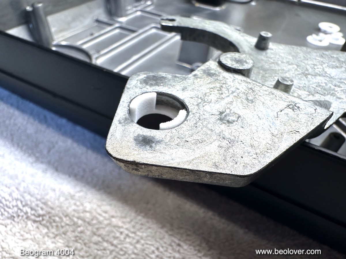
This is an impression of the original setup that is being replaced by the board:

This schematic tries to make sense of the wiring around the capacitors and the voltage regulator:
For the installation of the new board this diagram does not need to be fully internalized. Simply match the colors of the wires with the labels next to the solder pads. This shows the board with all the connections in place:
Note that the 'thin blue wire' from the collector of the original voltage regulator (see below) needs to be moved over to the PCB. Solder it to the pad labeled "lgt. blue" up front where also the orange wire is connected. The blue wire connects the solenoid to the 45V coming from the rectifier.

Let's discuss the Beogram 4000 24V power supply a bit. The 24V rail is the main supply and energy provider of the Beogram. The motors, light bulbs as well as the circuitry that translates the commands from the 6V powered control logic beneath the keypad into actual behaviors of the Beogram are powered by it. The 6V supply that provides power to the control logic is only a marginal energy consumer since it only drives the logic chips producing control signals.
This is a clipping from the circuit diagram that shows the 24V setup (the red dotted rectangle indicates the parts replaced by the new Beolover board):
The rectifier 0D1 is fed about 46-49V RMS from the transformer secondary. The rectified voltage is smoothened by capacitor 0C3 into an unstabilized DC voltage of about 45V. This 'rough' DC voltage is fed into the collector of 0TR1, which is set up as an emitter follower controlled by a Zener stabilized ~24V voltage at its base. At the emitter of this voltage regulator a second big capacitor 0C4 removes most of the remaining DC ripple and a stabilized ~24V rail results.
This picture shows how this circuit is implemented in the Beogram 4000:
Since this regulator circuit produces a large amount of waste heat in the transistor, the transistor itself is bolted directly to the metal enclosure in its own metal compartment. This makes for an effective heat sink. The collector of the transistor is connected to the metal bar that clamps the transistor down (the screws go in from the bottom of the enclosure). Left and right of the collector bar the base and emitter leads poke out through insulating sleeves. The big maroon colored resistor on the left is 0R1, which pulls the Zener up to the unregulated 45V from the rectifier, which is connected to the collector bar via the red wire seen on top of the picture. The Zener itself is the metal can whose cathode is soldered to the base. The anode end of the Zener is anchored to GND, which is achieved by soldering the lead to the connection point of the two negative terminals of the biggest (3000uF) capacitor cans of the setup, which are also connected to GND via the black and green wires (see schematic above).
The blue wire that goes to the same solder spot like the red wire connects directly to the top of the arm lowering solenoid. In other words the solenoid directly gets the unregulated 45V and bypasses the 0TR1 regulator (this wire needs to be moved to the Beolover PCB during installation).
I think this explains why the B&O designers chose to regulate 45V down to 24V. The solenoid needs such a high voltage to actuate reliably, and apparently they did not see fit using a transformer with a 3rd dedicated secondary winding for the 24V rail. I guess in the 1970s it did not really matter that much if a device wasted almost 50% of its energy intake...;-), because this is about what this approach 'achieved'. 
Let's have a look at different ways that can be used to convert a voltage down:
This figure shows the three main ways to go from a higher voltage to a lower voltage:

The most straight-forward way is a simple voltage divider. In this figure the 'load' represents the entire 24V connected circuitry of the Beogram. If we want to go from 45V to 24V, we simply calculate R1 according to R1=((45V-24V)*R(load))/45V and as long as the load resistance remains stable we have 24V on the load. The problem with this setup is that the current is the same in R1 and through the load. In the case 45V->24V this means that R1 dissipates almost the same heat as the load, so close to 50% of the energy is directly wasted into heat.
The next step up is the voltage regulator like it is employed in the Beogram 4000. Here we replace R1 with an emitter follower and a zener/resistor divider that puts 24V on the base of the transistor. The great improvement with this approach is that it can keep the voltage pegged to 24V regardless of variations of the load resistance. In the Beogram example, the load resistance would for instance go down as soon as the platter motor turns on, which would draw more current. Whenever the carriage is moved the load resistance goes down a little, too. And so on, bulbs on/off etc....
Since loads are rarely constant, the voltage regulator is a popular and simple way to achieve a regulated stabilized voltage rail.
But since the emitter follower basically only replaces R1 and essentially still acts as a resistor, albeit a variable one, we get a similar heat dissipation like in R1 in the simple divider. In fact, it gets even worse, since we have to feed the Zener divider, which constantly carries a current to peg the base to 24V. This current is actually fairly substantial in the Beogram setup since the regulator is a simple bipolar power transistor with a low gain, maybe in the 25-50 range. This means that the base needs to constantly carry a current that is a few percent of the collector-emitter current through the transistor into the 24V rail, proportionally increasing the heat load. Hence the big 5W power resistor!
While this approach was maybe the best approach in the 1970s, it is not used much anymore in modern designs since we have now MOSFET transistors, which can switch at high speeds with a very low heat loss due to their very low ON resistance. This enabled the development of the so called buck converter, which is able to step down voltages with high efficiency. Modern designs can achieve 90-95%, minimizing heat loss dramatically.
A very simple schematic model of such a converter is shown in the above figure. At its heart the R1 resistor is replaced with an appropriately dimensioned inductor. This inductor acts like a resistor plus energy storage due to the fact that a coil upon turn-on has a high resistance due to the EMF that is acting agains the inrush current. As the magnetic field builds up in the coil the resistance drops asymptotically towards zero. So in the end a coil is basically like a straight wire with some residual Ohmic resistance.
So how do we go from 45V to 24 with this process? This is achieved by chopping the 45V input into a high-frequency 'pulse width modulated' (PWM) signal. This results in a continuous partial ramping up of the current in the coil during the ON 'duty' cycle, and a release of the stored energy in the coil into the load during the OFF (-duty) period when the voltage is cut.
As a consequence, most of the energy in the 45-24=21V drop that is wholly dissipated in the divider and regulator circuits is instead fed into the load!
Pretty cool (in the literal sense of the word!...;-)! Of course, nothing is free in nature, and the disadvantage of this setup is that there is a bit of noise on the output voltage caused by the incessant chopping of the input voltage. This is dealt with by connecting a reservoir capacitor across the load, which stabilizes the voltage. 
The above basic circuit also omits the necessity of a feedback based control circuit that adjusts the PWM duty cycle depending on the load resistance to keep the voltage on the load constant. So this setup is in reality quite a bit more complicated than the simple regulator circuit of the Beogram. Luckily, one does not really have to deal with this 'complication'. Nowadays integrated circuits take care of all of this and one simply has to select the right external components (i.e. resorts, capacitors and the inductor) for the desired output voltage and current needs.
The two traces at the bottom of the above figure show the result of the simulation: The chopped input voltage (green) and the resulting ripple on the output voltage (blue). With a fairly modest 100u cap the ripple comes out to about 27mV, or ~0.1% of the output voltage. The Beogram has 3000uF at the output (0C4), and so it is much smaller, probably easily in the range of the original regulator output.

Let's have a look at the actual 24V supply circuit on the new Beolover board:
The big 'box' in the back is the inductor and the small 8-legged integrated circuit in front is the buck converter. The passive components around it take care of the feedback to keep the voltage constant.

Alright! On to some measurements! I measured the current draw into the 24V rail and the temperatures of the transformer and at one of the screws that bolt the motor down before and after the implantation of my new board.
It is important to state the motor voltage at which these measurements were made since this voltage directly influences the current draw of the 24V rail. This is a oscilloscope trace measured at the purple lead (the nice sine wave also demonstrates that my ceramic capacitor array works happily as motor phase capacitance):

The 13.3V amplitude I chose balances enough motor torque for sweeping dust off the record with a still reasonable current draw.
The temperature measurement location at the motor made sense since the voltage regulator is directly next to it and so I would measure the heat in the front left corner, coming from the motor and the regulator. This shows my measurement setup (Beolover PCB already installed):
The temperature meter above shows the two temperatures and the multimeter is hooked into the 45V line as current meter. The picture shows the current draw in ON condition with running platter. About 190mA go into the 24 power rail. This table shows the measurement results for the original setup vs. the new Beolover 24V supply:

The current difference in OFF condition is 70mA vs. 15mA (original vs. new) and 360mA vs. 190mA. We see that the power consumption of the 24V rail goes down my almost 50% in ON condition and about 80% in OFF (standby) condition. The better performance in standby comes from the absence of the Zener diode voltage divider, which is absent in the buck converter circuit on the Beolover board. In OFF condition the Zener divider represents the main power draw of the 24V rail.
The standby power draw of the original setup of 3.15W is pretty impressive. Considering the hours in a year (8760), this means that over a year about 27kWh are dissipated by a Beogram 4000 just by sitting on the shelf being plugged in. This is reduced to about 6kWh with the new Beolover circuit. Just to put it in perspective, 1kWh allows driving a typical electrical vehicle for about 2-3 miles. So this is a pretty substantial power waste for a standby audio device. 
This more frugal power consumption of the Beolover circuit became immediately evident in my temperature measurements. The original setup reached 47C at the motor and 41C at the transformer in ON condition (after about 1 hr runtime). In contrast, with the Beolover board installed much lower temperatures of 37C and 34C were measured, respectively. 
So in conclusion one can say that the Beolover board reduces power intake of the 24V rail by almost 50% while playing the deck, and by almost 80% while it sits in standby.
This Beogram 4000 has arrived in the modern age in power supply terms!


Friday, June 14, 2024

Beo4 Enabled Commander Remote Control: Seamless Integration of Beogram 4002 or 4004 with More Recent B&O Systems

A few months ago, Dirk, a fellow Beolover in Berlin, contacted me and suggested that it would be a nice thing being able controlling his Beogram 4004 with a Beo4 remote control. He has a Beosound 9000 in his living room, and wanted to integrate his Beogram in a way that it ideally would behave as a 'Beolinked' source.

I appreciated this idea and figured out how to modify the existing Beolover Commander remote. Basically, it needed a 455kHz capable IR receiver for communicating with a Beo4 and then I had to figure out how the Beo4 'ticks' in terms of codes it sends out in certain operational circumstances and rewrite the firmware.

Since the Beo4 is a fairly complex remote control with many modes, this was not trivial. But in the end I think I was able to arrive at a useful point, where the Commander equipped Beogram would pretty much behave as if it were connected to the Beosound via Beolink. 

I made a short video that demonstrates this system. The video contains footage that Dirk sent me. It shows how his Beogram interacts with his Beosound. He even figured out how to make a Beoremote One work with the Beo4 Commander! Very awesome! Enjoy:


The Beo4 Commander is available at the Beolover Store if you want to try this at home!..;-).


Tuesday, June 11, 2024

Beogram 4004 (5526): Full Functional Restoration, Installation of the New Beo4 Enabled Commander Remote and a Test Spin with Mr.T.!

This post summarizes the work done during the full functional restoration of a Beogram 4004 (Type 5526), which I recently received from a customer in California. This post discusses my initial assessment of the unit.

This picture shows the unit with the aluminum panels and platter removed:

As usual, I started with the DC platter motor. They all seem to need their dry bearings vacuum infused with fresh oil. Otherwise they produce significant RPM variations that can ruin any listening experience. This shows the removed motor:
I took it apart to get to the bearings. They are the small donuts on the black pad up front:
I immersed them in motor oil and pulled a vacuum. Immediately strong bubbling started:
The bubbling is indicative of air being drawn from the porous Oilite bearing material to make room for oil diffusion into the material. This process usually takes about 48-72 hrs.
In the meantime I focuses on the other restoration tasks. I began with the mechanical systems on the carriage, the arm lowering and the carriage transport assemblies. This shows the original setup:
I removed all moving parts and secured the carriage on a foam pad to protect the filigrane wires at its bottom side:
This shows the extracted parts ready for the ultrasonic cleaner:
While the carriage was separated from the floating chassis it was the perfect moment to check the cartridge connections (when I received this deck the tonearm was loose, suggesting there may be an issue with the connections that someone had a look into). I measured the continuity for all 4 cartridge connector traces (note: for this measurement the plug needs to be pulled from the output board) from the MMC tab to the connection terminal on the bottom side of the carriage. And indeed one of the traces was not connected through:
I pulled the arm off its base and had a look, and indeed there were only three wires connected (excluding the system ground wire). The green wire was awol:
Luckily, it was just pushed a bit into the arm tube
and I was able to pull it out with narrow tweezers. I soldered the wire to its terminal on the base:
It was probably ripped off when the arm was pushed back onto the base during a repair attempt. This easily happens if one is not careful since the wires can hang out below and then when the base is pushed in they can get caught and rip off.
Anyway, this was fixed and so I moved on to replacing the incandescent light bulb in the tracking sensor. This shows the original black tracking sensor bulb housing in place:
I removed it, which revealed the tracking feedback aperture:
Depending on the lateral arm deflection, it exposes a photo resistor in the lower part of the housing to more or less light, which is the control signal for the carriage advancement. This shows the original bulb and the Beolover Tracking Sensor LED Light Source in direct comparison:
The LED sits in the same location as the filament of the light bulb. This shows the part installed:
In the meantime the parts came out of the ultrasonic sparkly clean:
When I assembled the damper, I installed a new damper gasket:
The original black gaskets are usually hardened, which can result in inconsistent arm lowering speeds. So it is a good idea to replace this gasket whenever the damper is disassembled.
This shows the cleaned parts re-installed:
Beoshiny! I also put on a new precision machined aluminum pulley replica to replace the original cracked plastic one:
The final step on the carriage assembly was cleaning and re-lubricating the pivot point of the damper to arm linkage. It is mounted on the sensor arm assembly:
The linkage sticks out from the small V-cut in the metal piece bolted to the back of the counter weight. The sensor arm assembly has to be taken out for this procedure:
Thispicture shows the linkage removed:
I cleaned the small shaft on which it moves and re-installed the linkage:
As usual, the small copper plate that helps the arm move laterally in its up position came loose with a slight tweezer tug:
I removed the degraded double sided tape residue and glued it back in place with a dab of epoxy:
After re-aligning the sensor arm assembly it was time to restore the circuit boards. I usually begin with the main board. It has two power Darlingtons installed on its solder side. It is best to replace these transistors first with the board still installed. This simplifies aligning the replacements correctly that they line up with their mounting holes. This shows TR1, the TIP120 Darlington that regulates the 24V power rail:
I replaced it with a stronger TIP102 and also installed a (yellowish) 100nF capacitor between its emitter and ground. This capacitor quenches some strange high frequency oscillations that modern Darlingtons produce in this circuit configuration:
After also replacing TR4, the Darlington that controls the current through the solenoid, it was time to remove the board and focus on the component side. This shows the board in its original condition:
And after replacing all electrolytic capacitors, power transistor and the RPM replay and trimmers:
This show the rebuilt RPM section in detail with the new Beolover RPM relay (National style):
Next came the output board. This shows it in its original condition:
This board is the essential difference between Beogram 4004 and 4002. The 4004 version contains additional circuitry (on the left) that allows rudimentary control of the deck via the remote control of a Beomaster 2400. The actual output relay section is identical to what is usually found in 4002s:
I replaced all electrolytic capacitors and the output relay:
I also installed a (red) switch that conveniently allows connecting signal and system grounds in case there is a hum:
Then I focused on replacing the incandescent bulbs in the RPM panel above the keypad. This shows the panel removed and flipped over:
I removed the bulbs and prepared the assembly for the Beolover RPM Panel LED Backlights. They are the two small green/orange components in front the the panel:
The removed bulbs are below the LEDs. I installed the LED boards:
This shows one of them in more detail. They solder directly to the pads where the bulbs are connected, sort of an extension of the small PCB that makes the connections for the RPM panel:
The bulb covers can be reinstalled. There is no interference between the LED panels and the covers:
The final LED needing replacement is in the Sensor arm. This shows the small sensor compartment pulled out from the end of the arm. The original bulb is still in place and the Beolover Sensor Arm LED Light Source with its alignment piece is next to it on the right:
This shows the LED board implemented:
At this point pretty much everything was removed from the enclosure except the floating chassis. The next step was also removing their chassis to replace the completely degraded transport lock bushings. This shows one of them:
And hear the left-behind debris after taking out the floating chassis. A nice mess!:
I also removed the big reservoir capacitor that stabilizes the 21V rail:
And with that the enclosure was empty:
If you look closely you can see all the bushing fragments strewn around. Their removal is crucial during a restoration since they can impede the floating motion of the chassis and that reduces its capability to protect the turntable from vibrations. I vacuumed everything out:
Then it was time to install a new Beolover Transport Lock Bushing Set. These replacements are designed for easy installation. They each come in two identical halves that can installed by simply pushing one half in from the top and one from the bottom:
This is shown here:
Here one of the restored bushings is shown during the installation of the floating chassis:
And a photo of the completed lock:
Another advantage of the Beolover bushings is that they are a little thinner than the originals. This gives more leeway for adjusting the floating chassis properly.
With the chassis in place, it was time to install a new Beolover reservoir capacitor assembly. It comes with a red alignment piece that securely holds the circuit board with the capacitors in place:
Since this beogram had one of the later single capacitance type reservoir capacitors only two connections needed to be made, the white and black wires from the original capacitor need to be soldered to the respectively labeled solder pads on the PCB. With that done, the board can be bolted in with the screw that held the original capacitor in place:
Before I put the keypad back in, I replaced the cracked RPM panel holder on the right
with a new one from the Beoparts-shop in Denmark:
These parts are nice reproductions. All that needs to be done is move the metal spring parts over from the old cracked one.
After installing the keypad and the PCBs, I adjusted the bias of the new sensor arm transistor to yield the prescribed 4V at the collector:
After this adjustment I adjusted the platter height relative to the arms and made sure that the platter was also parallel to the arm travel. Then I adjusted the floating chassis in a way to get the platter flush with the aluminum panels. After this iterative and time consuming process, I focused on the remaining adjustments:
First I calibrated the tracking weight. Before I did the calibration I replaced the flimsy locking washer that holds the counterweight adjustment screw in place with a square M3 nut. This allows locking the calibration in place so it survives the rigors of shipping:
Then I adjusted the counterweight that the small weight dial was approximately accurate around 1.2g, which is the typical weight B&O cartridges demand:
The next step was adjusting the arm lowering limit to prevent desaster should the needle ever be lowered on a spinning empty platter due to a sensor malfunction:
Then I adjusted the tracking feedback.
My customer decided to get the original convertible DIN7 plug 
replaced with a modern gold plated DIN5:
DIN7 is only really needed if a Beogram 4004 is to be used with a Beomaster 2400. The two additional pins carry the remote signals to start/stop the deck via the Beomaster remote control.
All that was left to be done before a first test spin was putting the platter motor back together. The bubbling in the oil jar had stopped at this point and so it was time to extract the freshly re-infused bearings:

I installed them back in the motor enclosure:
And then I put the motor back together and installed in the Beogram for a 24 hrs RPM stability test with the BeoloverRPM device. This shows the BeoloverRPM installed on the rim of the enclosure performing a measurement in its 'slow' mode:
The 'slow' mode is perfect for precisely tuning the RPM and for longterm RPM stability measurements. It sends a RPM measurement every 10 sec to the serial port of the computer it is hooked up to. This is the curve I had measured after 24 hrs:
This is a pretty good result for a freshly restored Beogram DC platter motor. There is some longterm drift that is most likely related to temperature changes, and there are a couple small peaks that relate to the replenished bearing settling in place. The shaft needs to polish it in its new orientation. It can be expected that the RPM will still get a bit more stable after playing the deck for a few dozen hours. The 'noise' visible in this graph is a measurement artifact that comes from slight variations of the rib spacing around the platter. The BeoloverRPM essentially measures the time between ribs passing under its sensor.
This phenomenon can be more closely observed in the 'fast' mode of the BeoloverRPM, which plots an RPM value every time a rib passes under the sensor. The picture below shows the device in action and you can see a periodically repeating pattern on its screen:
This graph shows this measurement for about 60 platter rotations, i.e. the graph has about 60x24 measurement points (there are 24 ribs on a platter):

Each 'peak' corresponds to a platter turn. The repeating 'fine structure' of the peaks is essentially a fingerprint of this particular platter. In my experience it looks different for each Beogram. The superimposed sinusoidal looking curve shape is essentially a wow and flutter measurement. It shows the variation of the platter speed caused by the feedback based motor control system. The platter motor essentially feeds its speed back into the motor circuit, and whenever the speed is too high, the circuit regulates it down until it is too low, and then it gets faster again until the process repeats. This yields small periodic RPM variations that can be seen in this graph. Evaluation of the wavy part suggests that the wow and flutter variations are about 0.1%, which is about 2x than what the manual states (0.05%). This may be a real discrepancy, but it could as well be systematic since back in the 70s no digital RPM measurements were possible and this was done by measuring variations of a test tone on a test record. At any rate these fluctuations are way too small for humans to discern, and so we can conclude that this motor is back in business and can be used for listening to records!

And with this it was time for a test spin of this restored Beogram 4004!
I selected one of my favorite CTI records, "Don't mess with Mister T." (CTI 6030). The T of course stands for Stanley Turrentine! He recorded this album in 1973, a perfect contemporary for this lovely restored Beogram 4004! And what an awesome cover picture this album has. You definitely don't want to mess with Mr. T!...;-). Of course this lovely record was cleaned ultrasonically using a CleanerVinyl ProXL setup to restore its sound to its original glory. Here an impression of this great moment when everything came together:
After this test it was time to install the new Beo4 enabled Commander remote control:
The installation is exactly the same process, like for the standard Commander that uses an Apple remote. 
More info about the Beo4 Commander can be found here.
I will now play this deck for a while and if nothing new comes up, this Beogram will be ready to return to its owner!