Featured Post

Beolover SyncDrive: DC Platter Motor Replacement for Beogram 4002 and 4004 (Type 551x and 552x)

Late Beogram 4002 and the 4004 (Types 551x and 552x), which have DC platter motors instead of the earlier synchronous AC motors usually suff...

Showing posts with label cassette. Show all posts

Saturday, August 22, 2015

Beocord 9000: Rebuilding the Pinch (Rubber) Roller

The final crowning task to be completed on the Beocord 9000 that I am restoring right now was to rebuild the pitted and cracked pinch roller. Most of these decks have this issue. After all they are more than 30 years old! That is definitely exceeding the life expectancy of most rubber based products. I think a rebuild of the pinch roller is a must if one wants these decks to perform as new.

Luckily, there is Terry Witt at Terry's Rubber Rollers & Wheels. He is the world expert on rebuilding tape rollers and has a widely acknowledged authority on this topic...just visit some 'tape heads' blogs and chat rooms...;-). I think he does an outstanding job for an entirely reasonable price. So, don't bother buying second rate stuff on eBay with bad bearings and plastic wheels etc...just extract your original B&O quality rubber roller and send it to him! He is absolutely reliable and trustworthy! I made a short video about this procedure for the Beocord 9000. It shows how to get the roller out and put it back in. Enjoy!:

Monday, August 3, 2015

Beocord 9000: Restoring the Peak Program Meters with SMD LEDs

I recently successfully rebuilt the broken (4 missing segments) Peak Program Meter (PPM) of a Beocord that I had received for some TLC. Since this procedure was straight forward and had a nice result, we decided to also do it for the other Beocord 9000 I am working on, which still had an original PPM with all the segments working. I initially did not want to touch its PPM since I had never done one before, so like any good doctor I aimed to 'do no harm', while surgery was not absolutely necessary.

However, since the technology is the same as in the 7-segment counter display it is likely that some of the segments would have broken in the near future. So, while I still have it on my bench I think it is a great idea to do it now that I know how to make sure there are no issues in the near future.

Here are a few impressions of the procedure on this unit. Please, check for details in my original posts (post 1, post 2, post 3). As a fan of 'kaizen' I made a small further changes to the process by adding some glue to the restored plastic discs that hold the PPM covers down.

The original PPM still installed:

After removal:

Removing the covers by gently prying off the small plastic discs that hold them to the PCB:

Now they come off:


 This time I also removed the light guide for the scale illumination. It comes off anyway when one cleans the PCB with ethanol after soldering:
Now I was ready for soldering the SMDs in. This shows the green ones lined up for installation:
This shows them all installed and ready for testing:


At this point I usually do a 24 hrs test to make sure they are all o.k.

Now it was time to put the covers back on. So I clamped the covers and the light guide down and then recreated some resemblance of the small plastic discs by pushing the remaining stubs down with my soldering iron set to 200C. That just softens the plastic enough to be able to press it flat:


After this I put some small drops of Aleene's glue on the areas


and let them dry. This glue can be removed after soaking in ethanol for a while, so this is completely reversible.

I think this is a pretty good solution, at least for the Beocords since their displays are tightly held in place by the bezel that gets clamped over them, i.e. even if one of the spots came off, the covers would not be able to fall off.

Then it was time to install the rebuilt PPM. This required replacing the original current limiting resistors of the segments with larger values to account for the much higher efficiency of the new SMD LEDs. This shows the original resistors:
And here the new ones:

And after installing the PPM across the resistors.

Then I gave it a spin with a standard 1Vpp 1kHz signal at the inputs and the recording volume slider set to ~6. That gave me a nice full range on the meter. Beautiful these big segments!

That is it. All we need now is the rebuilt pinch roller that will soon come from Terry's Rubber Rollers. Then this baby will be ready for prime time!


Wednesday, July 29, 2015

Beocord 9000: Total Recap - Replacement of all Electrolytic Capacitors

I also did a full recap for my earlier Beocord 9000 restoration. While I think it is less urgent for Beocords and Beograms due to the generally lower operational temperature (than amplifiers/receivers), a replacement of all electrolytic capacitors is always a good idea if long term stability is desired. While the Beocord 9000 contains quite a few electrolytic capacitors, the good news is that its design is pretty service friendly. They definitely learned something between the 70s and the 80s. Even in comparison to the Beomaster 8000, the Beocord offers much easier access. In my opinion it is best to simply leave the main PCBs in the unit and instead remove the front and back panels. Here is a picture with the front panels removed. Their removal is straight forward and described in the service manual. Here is an impression of the top after removing the control panels and the glass cover:


The bottom PCBs can be accessed in a similar way by removing the bottom panel:


A good 'service position' for exchanging the capacitors is to put the unit upright opened like a book:


I put it on a towel, which allowed me to turn and move the unit while in this position. Once in this position it is time for some patience and concentration. One after another the caps are removed and new ones soldered in (in the correct polarity - as I said: concentration!! listen to some calm music and you will find some BeoZen in this..;-). Here are a few pictures:

Board #11 (DAC) is one of the two boards that need to be removed for the recap since they are sandwiched on top of another board:

 Before:
After:


The other one is #13 (Oscillator Detector)

Before:
After:


The following boards can be done while installed in the frame:

#8 Microphone Amplifier:

Before (the shield needs to be removed; it simply comes off when unsoldering the two spots that hold it in place):
After (shield already installed again):

#3 Rec/Play back circuit:

Before:
After:

#6 Rectifier

Before:
After:
It is worthwhile noting that the big 5000 uF cap was very close to be out of spec. It only yielded 4000 uF. This is still good enough for stabilizing the supply, but it shows that doing the recap was probably a good idea.

#4 Power Supply:

Before:
After:


#1 Microcomputer/display circuit:

Before:
After:
There is one cap on the upper part of this board. This shows it after replacement:

#2 Dolby circuits:

Before:
After:
O.k. done!


Tuesday, July 28, 2015

Beocord 9000: Restoration of the Peak Program Meter Scale Illumination

While the scale illumination light bulb was still working in the Beocord 9000 display that I am rebuilding right now, my customer decided to replace the bulb anyway to make sure that there are no unwanted surprises during return shipping. I can only agree since these light bulbs have a tendency to break their leads of during high vibration-situations (think speeding FedEx truck and a bunch potholes...;-). Once one is in there, I think it is best to simply replace everything and be done with it.
I did this procedure already once in the last Beocord 9000 that I rebuilt, which had a broken bulb.

Here are a few pictures to document the process for this particular unit:
This photo shows the original light bulb held in place by the 'cork' that sticks through the PCB

and from the back:
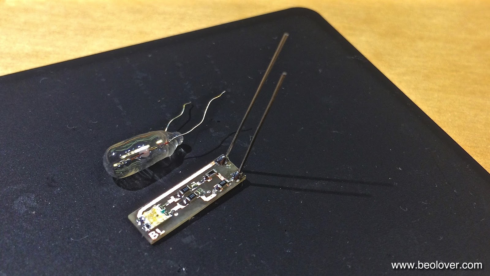
This is the PCB that I implanted. It is the same that I use in the Beogram 4000 to replace the position-scale incandescent bulbs.
It has almost the same width as the 5 mm bulb that they used in the Beocord 9000. I only use one red-green LED on the board for this application, i.e. I bridged the second LED position with SMD jumpers ("000"). It is important to replace incandescent bulbs with red-green LEDs if the light is being filtered or reflected by red or green features (like in this case where the scale is both green and red).

This picture shows the LED board inserted into the bulb space.

And from the back. It can directly be soldered to the solder points of the bulb, the polarity matches:

Here is a picture of the test drive:

On to the 7-segment display.


Monday, July 27, 2015

Beocord 9000: Replacing the RAM Battery

The Beocord 9000 has a 3V battery that supports the 16 word memory chip (an interesting MCM144102 chip that is mentioned as a peripheral memory unit in the Motorola 6804 manual, but whose detailed data sheet appears to be unavailable on the web). This chip stores the calibration settings (and may also back up the system time...not sure at this point - need to play a bit more with it). Here is a snapshot of the circuit:

The good news is that the battery is secured against connecting it with reverse polarity via D27. This suggests that replacing it with a battery holder instead of a soldered in tabbed version is a good way to proceed. 

The battery is located right underneath the TIME CAL indicator cabinet. The original battery started leaking the Li compound from the inside (that is the green-grey stuff around it). When I unsoldered the battery I suffered a small explosion due to this leaked compound. One should keep in mind that Li  is a highly reactive compound where a bit of heat immediately causes an exothermal reaction with the oxygen in the air. Luckily, I wore a magnifying visor and glasses, so nothing bad happened. But I would definitely recommend to cut the battery off with a wire cutter before starting to remove the tabs. Also wiping the area with ethanol would probably be a good idea to remove as much of the stuff as possible. Anyway, here is a picture of the vacated battery location after cleaning it as good as possible:

I used a 1/3N battery holder since tabbed 1/3N batteries are rare and pretty expensive. Also, a battery holder will enable to replace the battery in a few years without much fuss (the glass panel is removed very quickly without the need of a screwdriver, and then the battery can be accessed). Here is a picture of the new battery and the holder:

And the holder (Newark 25T0455) magnified:
Here is a picture after soldering it in. It is important to note the correct orientation that the + and - symbols match up with this on the PCB to avoid confusion down the road:

And with battery inserted:

Looks nice! Like it was designed that way (sort of strange to find a soldered battery in such a rarefied device, but then engineering of consumer devices usually assumes a 10 year use horizon...).