Featured Post

Beolover SyncDrive: DC Platter Motor Replacement for Beogram 4002 and 4004 (Type 551x and 552x)

Late Beogram 4002 and the 4004 (Types 551x and 552x), which have DC platter motors instead of the earlier synchronous AC motors usually suff...

Showing posts with label scale. Show all posts

Saturday, June 20, 2020

Beogram 4000: An Unusual Keypad PCB

This post is about an unusual keyboard PCB of a Beogram 4000 that was recently brought to my attention. Normally, the two position scale illumination bulbs in a Beogram 4000 are connected in series between the 24V rail and GND. This shows the bulbs on a standard board.
Below the PCB is the circuit layout as shown in the service manual. The way the bulbs are connected in series creates a situation where the polarity of them is reverse.
This is perfect for the installation of my (polarized) LED boards for replacing the bulbs:
When installed, these boards need to point in opposite directions to illuminate the entire position scale, i.e. their polarity is reverse relative to each other, which matches the above standard circuit layout, and both boards light up:
BTW: The red LED is the back illumination for the 33 RPM trimmer.

However, recently I received an email from another B&O enthusiast whom I supplied with two of these LED boards for his Beogram 4000 restoration, stating that only one of the boards was working in his Beogram! Very unbeolovely! After some more communication it turned out that his Beogram 4000 had a different keypad PCB, where two 24V bulbs were connected in parallel between the 24V rail and GND, instead of the normal two 12V bulbs in series.

This arrangement resulted in the same polarity for both of the bulbs, and this caused one LED board to be connected in reverse polarity, i.e. the LEDs did not light up. This situation is shown in the top-right picture in the slide below. 
He sent me a picture of this strange PCB (shown on the left). After a bit of head scratching it occurred to me that my LED boards could still be used if a small modification is made to the board:
By (1) removing one of the jumpers that connects one of the bulbs to GND, and (2) moving the 24V terminal to the solder point where the jumper originally connected towards the bulb, the standard in-series circuit was restored.
After this change was made, both LED boards started working (bottom right picture).
Beolovely again!

Saturday, December 5, 2015

Beogram 4002 (5521): Replacing the RPM Scale Illumination Bulbs with SMD LEDs

After replacing the broken light source of the tracking sensor, The next step of my current Beogram 4002 (5521) restoration was to replace the incandescent light bulbs in the RPM trimmer panel. The 33 RPM bulb was burned out, so we decided to replace both bulbs with my drop-in SMD LED assemblies. I am using red-green LEDs to ensure that there is a red light component to ensure proper illumination of the red RPM indicators. While amber LEDs can result in an incandescent-like look, they are not able to properly illuminate red surfaces due to their narrow wavelength distribution. Here is a picture of the small circuit boards that carry the LEDs as well as two current limiting resistors, one for the red and one for the green LEDs. This allows to tune the relative intensities to achieve an authentic looking illumination:

I recently made a video that shows how to exchange the bulbs with these boards. They are available to other enthusiasts. Just send me an email. 

Here are a few impressions of the installation in this particular Beogram. This shows the trimmer panel after removal:

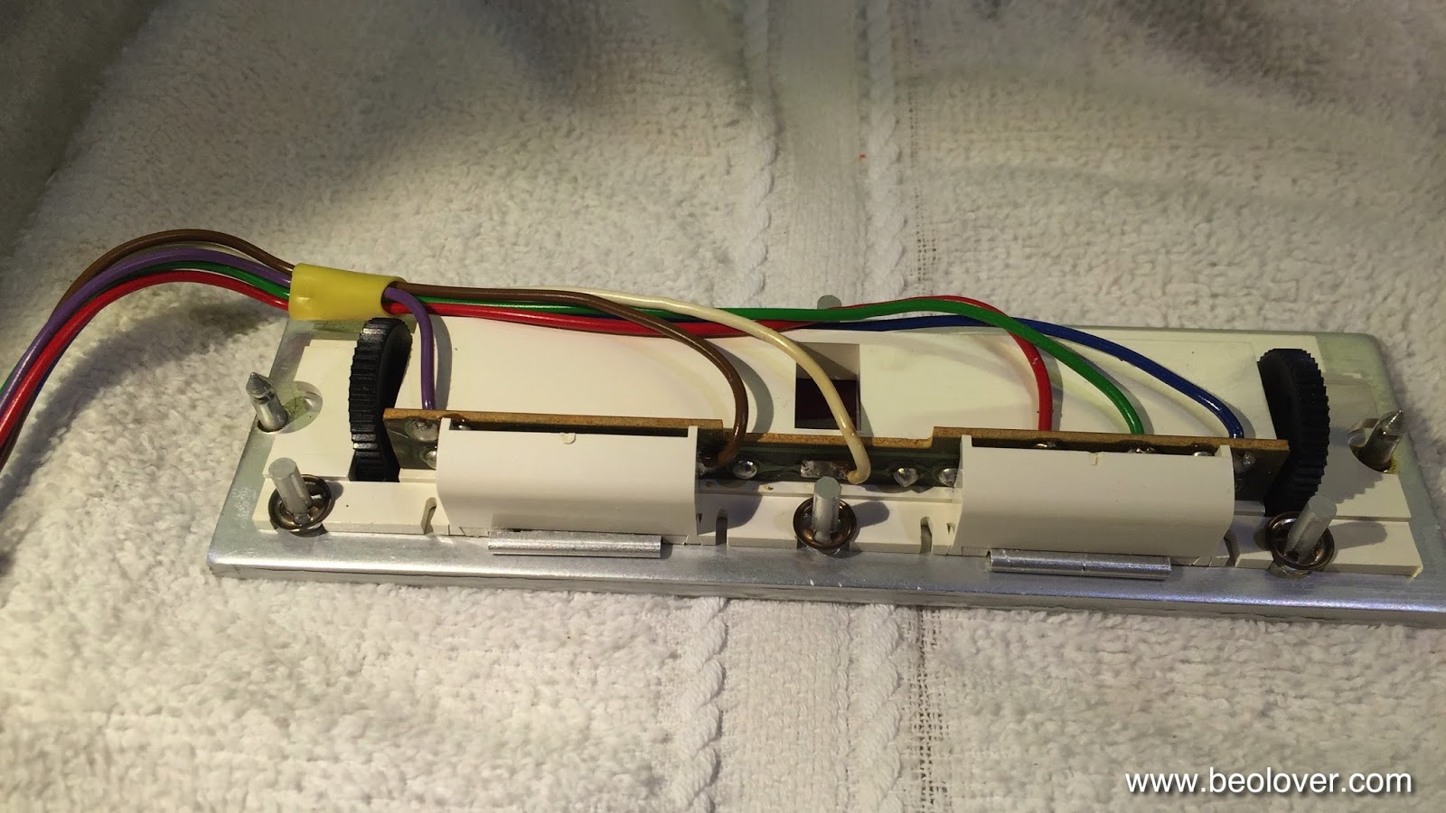
The bulbs can be accessed after removing the two covers:

After unsoldering the leads the bulb assemblies can be slid out:

Now the PCBs can be installed. It is important that they sit flush with the aluminum surface:

And then the covers can be replaced:

And that is it!


Tuesday, July 28, 2015

Beocord 9000: Restoration of the Peak Program Meter Scale Illumination

While the scale illumination light bulb was still working in the Beocord 9000 display that I am rebuilding right now, my customer decided to replace the bulb anyway to make sure that there are no unwanted surprises during return shipping. I can only agree since these light bulbs have a tendency to break their leads of during high vibration-situations (think speeding FedEx truck and a bunch potholes...;-). Once one is in there, I think it is best to simply replace everything and be done with it.
I did this procedure already once in the last Beocord 9000 that I rebuilt, which had a broken bulb.

Here are a few pictures to document the process for this particular unit:
This photo shows the original light bulb held in place by the 'cork' that sticks through the PCB

and from the back:
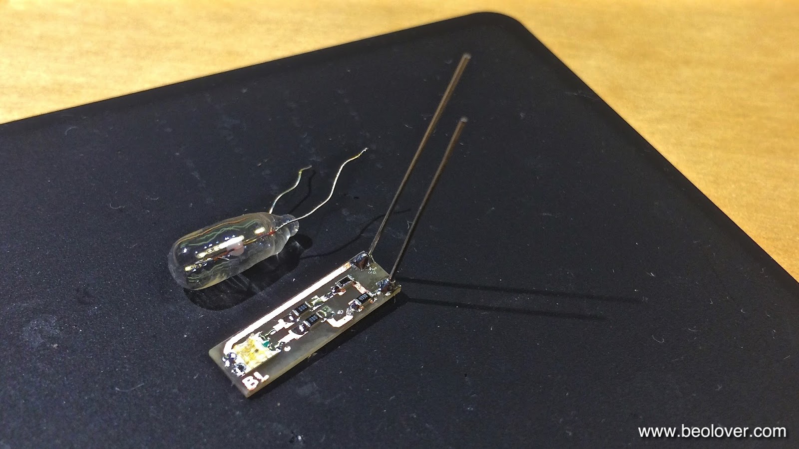
This is the PCB that I implanted. It is the same that I use in the Beogram 4000 to replace the position-scale incandescent bulbs.
It has almost the same width as the 5 mm bulb that they used in the Beocord 9000. I only use one red-green LED on the board for this application, i.e. I bridged the second LED position with SMD jumpers ("000"). It is important to replace incandescent bulbs with red-green LEDs if the light is being filtered or reflected by red or green features (like in this case where the scale is both green and red).

This picture shows the LED board inserted into the bulb space.

And from the back. It can directly be soldered to the solder points of the bulb, the polarity matches:

Here is a picture of the test drive:

On to the 7-segment display.


Monday, June 1, 2015

Beocord 9000: Peak Program Meter Scale Illumination with a Red/Green LED

After I put in the rebuilt 7-segment LED display back into the Beocord 9000 that I am restoring right now, I had to realize that the light bulb that illuminates the dB scale of the peak program meter broke off one of its leads. This happens often to these old light bulbs. They seem to mostly die this way. The leads oxidize and then break off when stressed. And there was definitely a bit of stress when wrangling the display bezel back over the display PCBs.

This is how it looked before the repair. No numbers show in between the PPM LEDs:

I examined the situation. The bulb sticks into a total internal reflection wave guide that feeds light into the space between the PPM LEDs. Matching the positions of the numbers in the mask in the bezel the surface of the wave guide is roughed a bit to diffuse some light out, hence back-illuminating the numbers. Here is a picture of the bulb as it sticks its head into the guide:

The bulb is held in place by a 'cork' that is pressed into an orifice below the bulb. Here is a picture from the other side of the PCB:

I extracted the bulb and the cork:

I aways try to replace these sensitive bulbs with LED based replacements to achieve better shipping survivability as well as longterm stability (I hope they will still sell cassette tapes in 30 years...;-). The bulb has a 5mm diameter, and the waveguide has an opening that is a bit larger. I encountered a similar situation when I upgraded the tonearm position indicator illumination of the Beogram 4000 that I rebuilt recently. For that case I developed a special PCB that holds two red/green SMD LEDs to achieve an incandescent look and a red scale indicator. I checked and found that these PCBs perfectly fit into the cavity in the waveguide. So I adapted one of them by just soldering one LED on it and bridging the space of the second one that is in series on this board.
The Beocord 9000 scale illumination also needs red and green LEDs since the positive dB values show in red, while the negative ones appear in green. An amber LED would not work since LEDs generate their light by a semiconductor transition, i.e. there is only the specific wavelength of the particular LED color present. So if red or green light is filtered out to achieve red or green scale illuminations amber does not fit the filters, i.e. the light will be suppressed or show amber at a low intensity, but not red or green.

Here is a picture of the adapted PCB:

I used a high brightness red/green LED (Newark 75R0619)  in combination with a 499 Ohm resistor for the red LED and a 2k resistor for the green one, which has a higher luminescent efficiency. This adapted the LEDs to the 6.2 V bulb supply and achieved the proper brightness.

This picture shows it in action after soldering it into the light bulb spot: 

It is held securely in place by two strong leads from below. Luckily the for-Beogram 4000-designed PCB had the "+" and "-" tabs in the right orientation, so the jumpers are not crossed:

Here is a shot of the wave guide under LED illumination:

And with bezel installed:

For comparison: This is the display in my own Beocord 9000 that still has the original light bulb:

Very similar appearance. The LED version is actually a bit more color-true since incandescent light bulbs are not very good at making green light. The LED illumination is also a bit more even since the light is piped into the guide in a directed fashion due to the narrow emission angle of LEDs.


Saturday, May 2, 2015

Beogram 4000: Replacing the Light Bulbs in the Control Panel with LEDs

After replacing the reservoir and motor capacitors in the Beogram 4000 that I am fixing up right now, it was time to give the light bulbs in the control panel some attention. I always like to replace all incandescent light bulbs with LEDs to make these units more stable for the long run. There really is no reason to stick with light bulbs except in a few situations where for circuit or vintage looks reasons bulbs are still the preferred solution. In the control panel, LEDs can be used without penalty since there is no direct path of the light to the outside. In this particular unit, one of the bulbs in the position scale was out, which rendered the entire scale dark since the two bulbs that illuminate it are in series. 

I designed a small circuit board to hold two red/green SMD LED assemblies with their current limiting resistors designed to create a light mixture resembling incandescent light. I always use red/green LEDs if vintage scales with red indicators are to be illuminated. The reason is that amber LEDs that often can be used for incandescent bulb replacement do not emit red photons, and without them red items cannot be properly illuminated. 
The two light bulbs that back-illuminate the RPM trimmers were replaced with standard high brightness red LEDs and appropriate current limiting resistors. 
I made a brief video that shows the entire process from removing and opening up the control panel to inserting the LEDs and replacing the assembly back in the Beogram:


Here are a few pictures from the video:

These are the red/green LED assemblies for the scale illumination (Newark 75R0619 with 1.25k for red and 6k for green:)


The RPM trimmers were replaced with this (LEDs: Newark 08R2974 with 3.3k resistors - the photo shows 1k resistors, and that was way too bright):


This shows the LED assemblies installed:


And lit up:


This shows the control panel in operation with the LEDs in place. This looks pretty authentic. We decided to make the RPM trimmers a bit brighter than original to make them visible when the light is on in the room. The original brightness is so low, that one has to practically turn off the lights in the room to be able to see them at all. But this could of course be adjusted by using larger resistors for the LEDs. An identical look to the original very low brightness can also be achieved with low output LEDs (Newark 14N9416) and 220 Ohm resistors: