Featured Post

Beolover SyncDrive: DC Platter Motor Replacement for Beogram 4002 and 4004 (Type 551x and 552x)

Late Beogram 4002 and the 4004 (Types 551x and 552x), which have DC platter motors instead of the earlier synchronous AC motors usually suff...

Showing posts with label peak program meter. Show all posts

Monday, August 3, 2015

Beocord 9000: Restoring the Peak Program Meters with SMD LEDs

I recently successfully rebuilt the broken (4 missing segments) Peak Program Meter (PPM) of a Beocord that I had received for some TLC. Since this procedure was straight forward and had a nice result, we decided to also do it for the other Beocord 9000 I am working on, which still had an original PPM with all the segments working. I initially did not want to touch its PPM since I had never done one before, so like any good doctor I aimed to 'do no harm', while surgery was not absolutely necessary.

However, since the technology is the same as in the 7-segment counter display it is likely that some of the segments would have broken in the near future. So, while I still have it on my bench I think it is a great idea to do it now that I know how to make sure there are no issues in the near future.

Here are a few impressions of the procedure on this unit. Please, check for details in my original posts (post 1, post 2, post 3). As a fan of 'kaizen' I made a small further changes to the process by adding some glue to the restored plastic discs that hold the PPM covers down.

The original PPM still installed:

After removal:

Removing the covers by gently prying off the small plastic discs that hold them to the PCB:

Now they come off:


 This time I also removed the light guide for the scale illumination. It comes off anyway when one cleans the PCB with ethanol after soldering:
Now I was ready for soldering the SMDs in. This shows the green ones lined up for installation:
This shows them all installed and ready for testing:


At this point I usually do a 24 hrs test to make sure they are all o.k.

Now it was time to put the covers back on. So I clamped the covers and the light guide down and then recreated some resemblance of the small plastic discs by pushing the remaining stubs down with my soldering iron set to 200C. That just softens the plastic enough to be able to press it flat:


After this I put some small drops of Aleene's glue on the areas


and let them dry. This glue can be removed after soaking in ethanol for a while, so this is completely reversible.

I think this is a pretty good solution, at least for the Beocords since their displays are tightly held in place by the bezel that gets clamped over them, i.e. even if one of the spots came off, the covers would not be able to fall off.

Then it was time to install the rebuilt PPM. This required replacing the original current limiting resistors of the segments with larger values to account for the much higher efficiency of the new SMD LEDs. This shows the original resistors:
And here the new ones:

And after installing the PPM across the resistors.

Then I gave it a spin with a standard 1Vpp 1kHz signal at the inputs and the recording volume slider set to ~6. That gave me a nice full range on the meter. Beautiful these big segments!

That is it. All we need now is the rebuilt pinch roller that will soon come from Terry's Rubber Rollers. Then this baby will be ready for prime time!


Tuesday, July 28, 2015

Beocord 9000: Restoration of the Peak Program Meter Scale Illumination

While the scale illumination light bulb was still working in the Beocord 9000 display that I am rebuilding right now, my customer decided to replace the bulb anyway to make sure that there are no unwanted surprises during return shipping. I can only agree since these light bulbs have a tendency to break their leads of during high vibration-situations (think speeding FedEx truck and a bunch potholes...;-). Once one is in there, I think it is best to simply replace everything and be done with it.
I did this procedure already once in the last Beocord 9000 that I rebuilt, which had a broken bulb.

Here are a few pictures to document the process for this particular unit:
This photo shows the original light bulb held in place by the 'cork' that sticks through the PCB

and from the back:
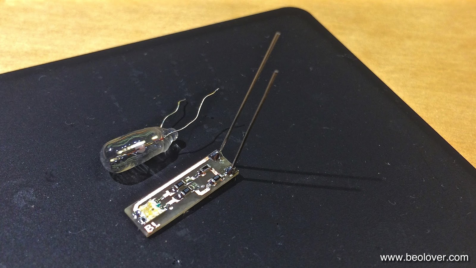
This is the PCB that I implanted. It is the same that I use in the Beogram 4000 to replace the position-scale incandescent bulbs.
It has almost the same width as the 5 mm bulb that they used in the Beocord 9000. I only use one red-green LED on the board for this application, i.e. I bridged the second LED position with SMD jumpers ("000"). It is important to replace incandescent bulbs with red-green LEDs if the light is being filtered or reflected by red or green features (like in this case where the scale is both green and red).

This picture shows the LED board inserted into the bulb space.

And from the back. It can directly be soldered to the solder points of the bulb, the polarity matches:

Here is a picture of the test drive:

On to the 7-segment display.


Monday, July 27, 2015

Beocord 9000: Restoration of the Peak Program Meter with SMD LEDs (III)

This is the third installment of my report on how to rebuild the peak program meters (PPM) of a Beocord 9000. The first two posts report on the installation of SMD LEDs to replace the original faulty LEDs on the PPM PCB, and the re-attachment of the plastic covers. This post demonstrates the installation and brightness adjustment of the rebuilt PPM.
The first step was to replace the original current limiting resistors with the correct values for the modern SMD LEDs. Modern LEDs typically need much less current and achieve higher brightness than the original LEDs. This is reflected in the much larger resistor values that my initial experiments yielded to achieve similar or slightly increased brightness with the new LEDs. The original values were 180 Ohm for the red and 120 Ohm for the green ones. The SMD types required 470 Ohm for red and 330 Ohm for green for slightly enhanced output (see first post). The resultant currents were in the 10 mA range, while the original LEDs easily draw 40 mA, while having a lower intensity.
Here is a picture of the original resistor bank (the 8 leftmost resistors)
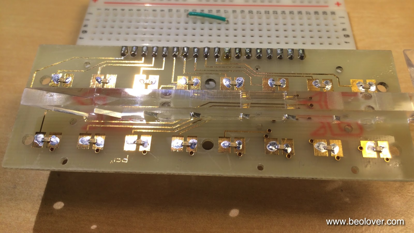
This shows the new resistors installed. Despite the PPM having 16 LEDs there are only 8 resistors. This is due to the fact that the two left and right PPMs are multiplexed at 60 Hz, i.e. only 8 are on at a time. This is seen in the signals of the two common anodes (pin 1 and 2 on the display board) which each drive one of the PPMs:

This shows the new resistors installed:


And here after installation of the rebuilt PPM:
And in action:

It turned out to be a good idea to fix the two display boards in sequence, i.e. leave one in while taking out the other. this allows to realign the one that was out with the one that is still in when putting it back. That way it is easy to get it back into the right position that it fits perfectly into the plastic bezel. Another helpful thing to do is to mark on the headers of the displays how far they were inserted into the PCB. This is important to get the right slant of the displays that matches the cover.
On to replacing the scale illumination bulb with a red/green SMD LED.

Friday, July 24, 2015

Beocord 9000: Restoration of the Peak Program Meter with SMD LEDs (II)

The 24 hrs test of the rebuilt Peak Program Meters (PPM) of the Beocord 9000 display that I am rebuilding was successful:


So I set out to reattach the red-green covers. Encouraged by my recent rebuild of a Beocord 9000 counter display, I decided to rely on melting the plastic posts of the red-green covers with my soldering iron set to 200C to recreate the original attachment method. First I needed to clamp the display together, however, to ensure that the covers would make a tight bond with the PCB to avoid light escaping through cracks at the bottom:

I applied the clamps in a way that the cover posts were still accessible and then I melted them by rolling the solder iron tip cone over them. This worked quite nicely:

When I cleaned the PCB with ethanol after soldering the SMD LEDs, the glue that held the light guide down dissolved. This told me that this clear glue was most likely some kind of polyvinyl ester based carpenter glue. So I used 'Aleene's Original Tacky Glue', which is my mainstay for bonding speaker foams to the cones. This glue dries clear, recreating the original look of the bonds:

After the glue was hardened, I put the display again to a 24hrs test to ensure that nothing bad happened during the reassembly:

What a beautiful design! I can't wait until I can make a test-recording with this deck using these lovely big rebuilt PPMs.


Beocord 9000: Restoration of the Peak Program Meter with SMD LEDs (I)

While I am waiting for the pinch roller for the Beocord 9000 I am finishing up, I started working on another 9000 that needs the displays rebuilt. Cassettes are definitely back! I hope they will start manufacturing new tapes again (and SONY decides to restart the production of the Walkman II...but that is an entirely different story...;-).
Anyway, here is a picture of the sad state of this display:

Not shown here, but the TIME CAL bulb is also dim, like on the other 9000. I decided to attack the VU or 'peak program' meter (PPM) first, since I never did this type of display before. Beolover excitement, no doubt! After opening the Beocord up, the first step is to remove the display bezel that covers the boards and also holds the translucent windows:
After taking the bezel off:
The I unsoldered the PPM board:
The next step was to remove the plastic covers. It turned out that there are black cardboard strips inserted between the covers and the light guide for the scale illumination:
The plastic covers were fixed to the PCB by melting their protruding plastic feet and flattening them, which creates round shaped 'seals':
These must be removed before the covers can be lifted:
I decided to leave the light guide in. Here is a picture after taking the covers and strips off:
For the fun of it, I piped some light in from the side where the scale illumination bulb sits. One can see nicely that the triangular cutouts in the bottom act as mirrors that reflect light to the positions where the scale numbers are:
After playing with this I started working on the rebuild. The first task was to determine the right resistors for the new SMD LEDs. First I determined the values needed to achieve an identical brightness to the original LEDs. For this I replaced a red and a green one of the four broken LEDs with SMD LEDs (Newark 75K1441 (red 14MCD 2.0V) and 75K1440 (green 18MCD 2.1V):
then I rigged the setup with resistors and ran it:
And with covers on:
It turns out that values of about 1k Ohm for red and 670 Ohm for green at 6.2V yield similar brightness. Note that the red LEDs had a similar brightness difference as the green ones, but the camera was not able to show this very well.

My client decided to ramp the brightness a bit up that the displays are better visible in brightly lit rooms. So I determined values that will make them match well with the higher brightness 7-segment display of the counter and indicator light SMD replacements that I usually use.
Here is a picture of the higher brightness version in comparison with the original LEDs:
The values that do the job are 330 Ohm for green (yielding 12.6mA) and 470 for red (9.4mA)
After this tests, I replaced all LEDs with SMD versions:

And running at 6.2V with the above resistor values in series:

Beautiful!! I will let this run for 24hrs before I reattach the covers to make sure that there are no problems.


Sunday, January 18, 2015

Beocord 5000 (4715/4716): Calibrating Recording Current and Bias

Happy that the Beocord 5000 (4715/4716) tape mechanism seemed to work, I made a first test recording using my waveform generator. When playing back the tape, I realized that one of the channels was off by about 3 dB on the Peak Program Meter (PPM). This meant that the calibration of the deck was off. Not a surprise, considering the age. I guess this also meant that I was just lucky with the first Beocord 5000 that I rebuilt for my Beolab 6000 set-up, which performs admirably without doing a thorough calibration. Anyway, I felt that the first step towards a solid calibration would be to get a reliable 'frequency response' measurement in place. Frustratingly, none of my bench equipment offered anything useful in this direction. I looked around for free software that would let me do such measurements with my computer (the audio range is quite unchallenging to modern sound cards in PCs).

I was not able to find anything open source that would enable such measurements without too much hassle. But I finally found the 'audioTester', which was written by an enthusiast (Ulrich Müller) in Germany. He offers an evaluation shareware version that allows to do measurements for 10 min before a restart becomes necessary. I downloaded this version onto my old MacBook Pro that I use as my go-to Windows 7 PC in Bootcamp mode whenever I need to use PC-only software. The installation went well and the built in sound card of the MacBook seems adequate for the task. After a bit of experimentation (the owners manual is a bit scant) I was able to make a non-synchronized sweep-measurement to determine the frequency response. It needed to be a non-synchronized measurement since the 2-head Beocord does not offer a monitor function for listening to the recording during the recording process. During a non-synchronized measurement the software determines the frequency of the sound and plots the signal level relative to the measured frequency. This means that for a response measurement, one needs to record a sine wave sweep across the entire spectrum (I did a 60s logarithmic sweep from 10-20kHz), then rewind the tape and during playback the measurement is done. I tested the mechanism by directly feeding the 60s sweep from my waveform generator into the audioTester. The measurement yielded a constant level across the entire spectrum, indicating that the signal path through the MacBook sound card was linear.

After this I did a baseline measurement of the Beocord at 0dB. This requires to adjust the signal level for recording in a way that the Dolby B ICs put out 740mV(RMS) signal at their pin 7. This can be achieved by setting the waveform generator to an amplitude of about 50mV(pp) and using the recording level potentiometer to adjust the recording level to 740mV(RMS) at pin 7 on both ICs for left and right signal path. Dolby should be switched off during calibration.

Here is a shot from my oscilloscope of the 0dB signal at pin 7 at 333kHz (the pp voltage of 2.3V is 0.2V too high due to noise). The RMS voltage is shown at the bottom right corner of the screen.:


Oscilloscope probe at pin 7 of the Dolby B IC for the right channel: 


After recording the sweep, the payback yielded this frequency response curve:


I was still in the learning process with the 'audioTester, which is the reason that the curves only start at 100Hz, but it is obvious that for high frequencies there is a several dB difference between the channels. This explains the discrepancy on the PPMs during playback.
So I set out to do a calibration. I followed the procedure outlined in the service manual. This procedure first adjusts the recording current that playback and recording signals are the same at pin 7 at 333Hz. This adjustment is done for a medium signal level of 200mV(RMS) at pins 7 of the Dolby ICs. The recording current is adjusted with the trimmers 1R99/47 for CrO2 tapes (I used a TDK SA 90). 
So the first step is to adjust the Dolby B output to 220mV(RMS):
The procedure to get the right adjustment is simply to make a recording, play it back and monitor the signal at pins 7. If the signal is too high turn the respective trimmer (L or R channel, and tape type)clockwise, if it is too low, counter clockwise. Repeat until about 200mV are achieved during playback. The trimmer adjustment is pretty sensitive, i.e. small steps (~5 degrees) are advised. On this pic I am adjusting the left channel during the calibration for a Fe2O3 tape:


Once the recording current is adjusted properly, it is time to do the 'bias' adjustments. This adjustment sets the amplitude of the 92kHz bias signal that is fed into the erase head. This signal needs to be of perfect amplitude that high frequencies can be recorded properly. The amplitude of the bias signal is adjusted with trimmer capacitors that tune the resonance frequency of a pickup coil that takes the signal up from the bias oscillator.

The procedure for this adjustment is as follows: Set input signal to 333Hz and 22mV(RMS), adjust record level potentiometers that you get 740mV(RMS) on pin 7 of the Dolby ICs. Now reduce the amplitude of the input signal by a factor 20 (-26dB) to 1.1mV (RMS). If the PPMs are calibrated right, only the lowest lamp should be on for each channel. Now set the input signal to 15kHz and adjust the bias trimmers for both channels (C70/72 for CrO2, and C71/73 for Fe2O3) that during playback the same -26 dB signal is seen at pin 7  (37mV RMS) as during recording. Here is a picture when I adjusted the right CrO2 trimmer:

Unfortunately (if one does not have the special tool that fits into the trimmers from the solder side of the PCB - I might 3D print myself one someday...;-), one needs to lift the preamplifier PCB every time an adjustment is made, while the recording requires the board in place that the recording switch can be activated by the solenoid, and that the board is properly grounded. Hence, this is a bit an annoying process. Also the trimmers are very sensitive, i.e. there are a few adjustment cycles to go through until the bias is adjusted properly. 

After the calibration was done for both tape types I measured the frequency response again with the audioTester. Here are the results (I compiled them into Excel graphs for both tape types):


It is remarkable that there is little difference between the two tape types. This is probably a testament to the quality of modern Fe2O3 tape materials. As to be expected the low level (-20dB for CrO2 and -26dB for Fe2O2) are much better at high frequencies than the 0dB curves and reach smoothly to 15kHz. This difference between low and high levels is a common trait of all tape recorders. It is also nice to see that the Dolby B system does not seem to introduce significant distortions. The curves are almost indistinguishable from the non-Dolby curves.

It is interesting to compare these curves with some curves of high quality 3-head decks that are posted online. These curves show a surprising wide range of curve shapes, some even with oscillatory features in them. It seems that the Beocord 5000 holds its own, especially when considering that the measured 3-head decks are all much more 'younger', and that all have a monitor function, i.e. the response was measured during the actual recording process, which optimizes tape positioning etc...