Featured Post

Beolover SyncDrive: DC Platter Motor Replacement for Beogram 4002 and 4004 (Type 551x and 552x)

Late Beogram 4002 and the 4004 (Types 551x and 552x), which have DC platter motors instead of the earlier synchronous AC motors usually suff...

Showing posts with label 67SSBG4000. Show all posts

Friday, May 22, 2015

Beogram 4000: Adjusting the Platter and the Chassis

After performing all necessary restoration tasks on the Beogram 4000 that I restored during the last few weeks, I put the aluminum panels back on. I quickly realized that the platter was not flush nor centered relative to the surrounding aluminum panel. This meant I needed to adjust the chassis and platter positions. The service manual prescribes to adjust the platter first relative to the chassis, and then adjust the chassis poison relative to the enclosure, i.e. the aluminum platter surrounding the platter to create a situation where the platter is flush with the panel and also centered in the opening. In other words the task was to achieve a Beoloving situation where the Beogram looked just perfect!

I made two short videos describing the the process. Here is the first one, that describes how to adjust the platter relative to the chassis:


After the platter is adjusted the chassis can be aligned. This procedure is shown in the second video:


Well, this pretty much concludes the restoration process. I am almost sad, since I really got used to this most beautiful piece of engineering, and I will have a hard time to let this Beogram 4000 go back to its owner! I am grateful to Jacob Jensen for coming up with such wonderful designs. They enrich my life and they also got me turned on to electronics. It has been a wonderful experience the last few years! Of course I never met him, but it feels like I just lost a friend! Rest In Peace! It is Beolove!

Monday, May 18, 2015

Beogram 4000: Polishing the Hood

A last labor-of-beolove tribute to the Beogram 4000 that I restored in recent weeks: Time to polish the hood! It is always quite a workout. It usually takes me several hours in a multi-step process. This Beogram had fairly damaged plexiglass surfaces. Here are a few impressions:


Whenever there are deep scratches that one can feel with a fingernail, then it is time to crank out the 220 grit sand paper. With that the surface needs to be sanded until the deep marks are gone, and only the homogenous scratches from the sandpaper are visible. This hood definitely needed this drastic step. But first the B&O trim needed to be protected. It is very easy to 'delete' the B&O labels in the heat of battle when going at it with the sanding block. I usually use three layers of insulation tape:

After this I gave the 220 grit a go:


Looks almost like wood after this step. Once you have a smoothly sanded surface, it is time to work your way back to shininess. This is done by using about 10 grades of sand paper and micro-mesh policing cloths. This is finished with polishing liquid. It is important to change the sanding/polishing direction between every step. Also avoid rotating motions, it is best to just go in linear strokes. The chance in direction allows to see whether one has polished all the scratches left behind by the previous coarser step behind. Here are a few pictures taken in between the steps (not all are shown, but you get the idea):

After 400 grit:
After 800:
After 1800 Micro-Mesh
After 3200 Micro-Mesh:
After 6000 Micro-Mesh:

After Micro-Gloss polishing liquid:

And that is pretty much as good as this can get...it is virtually impossible to get back to 100% like new. But one can get pretty close. And this pretty much concludes the restoration process of this Beogram 4000!


Thursday, May 14, 2015

Beogram 4000: Adjusting the Solenoid and the Switches

Still a few odds and ends to take care of in the Beogram 4000 that I am rebuilding right now. Any complete restoration should include an adjustment of the solenoid and the switches that it controls to specifications. The solenoid not only takes care of the tonearm lifting and lowering, it also actuates three switches that control the audio muting function, the solenoid current (power), and the carriage transport enabling function. The audio muting switches are responsible for grounding the cartridge coils until after the needle has hit the record. The solenoid current limiter is responsible for lowering the current in the solenoid once it is engaged. This prevents the solenoid from overheating while the record is playing and the arm is down for extended periods of time. The carriage transport enable switch enables the servo motor once the arm is down. This prevents accidental carriage motion in case the arm is touched when it is up.

I made a short video that discusses the circuit and shows how to adjust everything to specifications. Enjoy!:

Wednesday, May 13, 2015

Beogram 4000: Adding a Grounding Switch

The Beogram 4000 that I am currently restoring exhibited a quite nasty hum when I initially hooked it up to my Beomaster 6000 and played a record. This was strange since the Beogram 4000 has the same grounding setup as the Beogram 4002, and my 4002 has no hum at all when connected to my Beomaster 6000. The only difference between the two models in terms of grounding and hum etc...is the non-shielded mains transformer in the 4000. The later models all have shielded transformers that sit in metal cans. I am not sure if this matters, but this seems to be the only real difference. Both have double shielded DIN 5 cables and their chassises are floating. So a strange thing...but then this is a grounding issue, and they can sometimes be pretty strange. I measured the resistances between signal, and system grounds and the chassis, and everything seems to be up to spec. The transformer is also fully insulated, so there is no direct galvanic connection anywhere. So the only thing that comes to my mind at this point is EM interference from the transformer.

It turned out that when I tied the signal and system grounds together, the hum was completely gone. So I decided to install a switch that allows to connect the two grounds or leave them separate, depending on what works best with whatever amplifier the Beogram is connected to. In essence, connecting the two grounds establishes the same setup as in a Beogram 4004, which is the latest 400x grounding configuration. Maybe B&O went through a learning curve with regard to grounding and hum etc...and they decided to tie everything together. In my opinion this is the best way to do it anyway since this creates low impedance connections between all the grounding leads, which results in much less susceptibility to EM interference.

I made a figure that summarizes the grounding and signal setup in the Beogram 4000:


The figure shows the switch. I used a toggle switch that I soldered directly to the DIN5 cable terminal, where it ties signal and system grounds when flipped to the left. When switched to the right, the grounds are separated, which is the original configuration.

The upper left picture also shows the grounding relay that is activated by the tonearm solenoid when the arm goes down. The terminals are connected in a non-intuitive way, where on both switches the contact studs (points) are tied together and carry the left channel signal, while the lower blade carries the right channel and the upper blade is connected to signal ground (exactly like shown on the circuit schematic). When the two switches close when the tonearm is up, everything is connected together, muting the signal to the amplifier.

Friday, May 8, 2015

Beogram 4000: Adjustment of the Tonearm Height and Tracking Force

The big things are pretty much done in the Beogram 4000 that I am restoring right now (except polishing the hood...I am saving this for a day when I can't make it to the gym. Polishing is always a nice workout...;-). So I am now focusing on the details. I noticed that the tonearm rested considerably higher than the sensor arm when in lifted position. Here is a picture taken from the front of the two arms:


While this is nothing important with regard to sound quality etc..., it just does not look great. After I consulted the manual, which prescribes to adjust the arm to the same height as the sensor arm, I did the adjustment. It is pretty simple. There are two screws in the back of the arms that set the upper and lower limits of the tone arm movement. They are accessible after taking off the carriage cover (it can simply be pulled up and away from the arms). The two screws are indicates with red and blue circles:

The red one sets the lower limit. Obviously, this needs to be set that the tonearm lowers the stylus slightly below the platter ribs (the manual prescribes 0.5 mm below the high portions of the ribs - please, do this measurement with the belt removed...;-). The blue one sets the upper limit. This is the one I adjusted. The other one was set correctly. A few turns and I arrived at the right tonearm height:

Beautiful! On to the tracking force adjustment. It is crucial that the pickup tracks the groove at precisely the right weight it has been designed for. In the case of the SP15 cartridge that came with this Beogram 4000, the proper weight is 1g. A while back I made a video demonstrating this adjustment on a Beogram 4004. The setup is identical on the 4000:


The important thing about this adjustment is that one needs to adjust the zero weight first with the weight that is in the back of the tonearm. Once this is adjusted, the correct tracking weight can be determined using a tracking force gauge by adjusting the weight dial in the back of the arm. In previous Beograms it turned out that the tracking force scale on the arm is often less than accurate. The Beogram 4000 however seems to be precise in this aspect. My measurements showed that the adjusted weight is very close to the measured one on the gauge.

Thursday, May 7, 2015

Beogram 4000: Replacing the Light Bulb of the Tracking Sensor with a Drop-In LED Assembly

Whenever I restore a Beogram 400x I also replace the tracking sensor light bulb with a LED assembly. I recently developed a drop-in replacement for the light bulb assembly for Beogram 4002 and 4004 models. For the Beogram 4000 I modified this part to include the B&O prescribed intensity trimmer that allows to adjust the gain of the tracking feedback mechanism of the 4000.

Whenever the light source of the tracking system is replaced, the sensor position of the mechanism needs to be adjusted to yield the correct tracking sensitivity. I made a short video about the entire process. The video also discusses the tracking circuit and gives a detailed account of the adjustment procedure:


Here are a few pictures of the parts: This is the original bulb assembly, which is not available anymore due to the proprietary housing shape into which the bulb is glued:

This are the components of the replacement part:


The PCB holds a high brightness LED (Newark 15R2204) and a 3k current limiting resistor, suitable for the 6V power rail in the Beogram 4000. The blue part is a 3D printed replacement of the lower part of the original housing, which fits precisely onto the sensor base. Both parts are then glued together, which generates a drop-in ready replacement assembly, where the LED is very near the location of the filament in the light bulb:

This shows the top side. For the Beogram 4000 I added a 2k encapsulated cermet trimmer (Newark 70M7250), which is very helpful for the correct adjustment of the tracking mechanism:

Here is a picture of the implemented assembly:

The LED runs at a very small current of less than 1 mA in this set-up, which should make it last for a very long time. It is rated 20 mA at full output.


Tuesday, May 5, 2015

Beogram 4000: Restoring the Slow Slide Transport Function

The Beogram 4000 that I am currently restoring had a tendency to continue moving the tone arm carriage ("slide" in the service manual parlance) whenever the carriage was moved fast or slow in reverse direction. It turned out that the keypad switch that controls the reverse direction was damaged due to an earlier repair attempt where the contact terminal was bent, with the result that the turn off contact was not stable anymore. Here is a picture of the terminal as I found it:


In order to fix this I had to remove the control panel, take out the circuit board and extract the switch terminals. This allowed me to bend the contact terminal back into shape and also clean the contacts throughly. This fixed the problem. I made a short video about the process. It discusses the slide transport circuit, how to remove the contacts and clean them and how to adjust the slow scan speed to specifications:


This shows the switch taken apart:

And the terminal after I straightened and cleaned it, and soldered it back in:


After I was done with the contacts, I also fixed this solder iron inflicted damage from some earlier repair-shop stay that left the conductor exposed:

I put some 1/16th shrink tubing on the damaged wire and soldered it back onto its terminal:

The next step is to put in a LED based replacement for the tracking sensor.


Saturday, May 2, 2015

Beogram 4000: Replacing the Light Bulbs in the Control Panel with LEDs

After replacing the reservoir and motor capacitors in the Beogram 4000 that I am fixing up right now, it was time to give the light bulbs in the control panel some attention. I always like to replace all incandescent light bulbs with LEDs to make these units more stable for the long run. There really is no reason to stick with light bulbs except in a few situations where for circuit or vintage looks reasons bulbs are still the preferred solution. In the control panel, LEDs can be used without penalty since there is no direct path of the light to the outside. In this particular unit, one of the bulbs in the position scale was out, which rendered the entire scale dark since the two bulbs that illuminate it are in series. 

I designed a small circuit board to hold two red/green SMD LED assemblies with their current limiting resistors designed to create a light mixture resembling incandescent light. I always use red/green LEDs if vintage scales with red indicators are to be illuminated. The reason is that amber LEDs that often can be used for incandescent bulb replacement do not emit red photons, and without them red items cannot be properly illuminated. 
The two light bulbs that back-illuminate the RPM trimmers were replaced with standard high brightness red LEDs and appropriate current limiting resistors. 
I made a brief video that shows the entire process from removing and opening up the control panel to inserting the LEDs and replacing the assembly back in the Beogram:


Here are a few pictures from the video:

These are the red/green LED assemblies for the scale illumination (Newark 75R0619 with 1.25k for red and 6k for green:)


The RPM trimmers were replaced with this (LEDs: Newark 08R2974 with 3.3k resistors - the photo shows 1k resistors, and that was way too bright):


This shows the LED assemblies installed:


And lit up:


This shows the control panel in operation with the LEDs in place. This looks pretty authentic. We decided to make the RPM trimmers a bit brighter than original to make them visible when the light is on in the room. The original brightness is so low, that one has to practically turn off the lights in the room to be able to see them at all. But this could of course be adjusted by using larger resistors for the LEDs. An identical look to the original very low brightness can also be achieved with low output LEDs (Newark 14N9416) and 220 Ohm resistors:


Wednesday, April 29, 2015

Beogram 4000: Replacing the Reservoir and Motor Capacitors Using a 3D Printed Adapter

Today I received the 3D printed adapter for the new reservoir and motor capacitors of the Beogram 4000 that I am currently rebuilding. Modern capacitors are considerably smaller than the original  1970s types, so a 3D printed adapter makes for a clean implementation with no wiggly or loose parts. 

Here are a couple impressions of the assembly with the new caps:


I replaced the original 150uF unipolar motor capacitor with two axial 300uF types back to back. The other capacitors are Rubycon, Panasonic and Multicomp 105C types for a long lasting setup. 

********Update: See here for a detailed view of how to prepare the replacement capacitor assembly before soldering the wires to it***********

This is the first time that I work on a 4000, hence, before I took the original setup apart, I made a detailed schematic of the wiring for the record in case there is confusion at some point during the operation. Mixing up some of the wires could potentially cause considerable havoc:

Then I unsoldered everything and put in the new capacitor assemblies:


Here is a detail shot of the classic Zener diode-based 24V emitter follower regulator setup. The regulating transistor is directly bolted (via an insulation pad) to the cabinet metal bottom for heat dissipation. The metal bar across the setup also serves as collector terminal. The Zener diode is the short can that is soldered between the current limiting resistor/transistor base node and the negative ends of the 3300uF reservoir caps that serve as system ground:
After a thorough double check of all connections, I plugged the Beogram in, and started it up. Everything seems happy! This is Beolove!


Monday, April 27, 2015

Beogram 4000: Adjusting the AC Motor Voltage

When I initially tested the Beogram 4000 that I am currently restoring, I noticed that the motor was running a bit noisy, especially at 45 RPM. After I replaced all the electrolytic capacitors, this got better, but did not go fully away. So it was time to look into the motor voltage and the waveform that is presented to it by the Wien bridge oscillator (a nice classic design including the amplitude control light bulb that acts as a variable resistor that increases its resistance as the current increases - pretty nifty!). The AC waveform amplitude can be measured at one of the motor leads relative to GND.

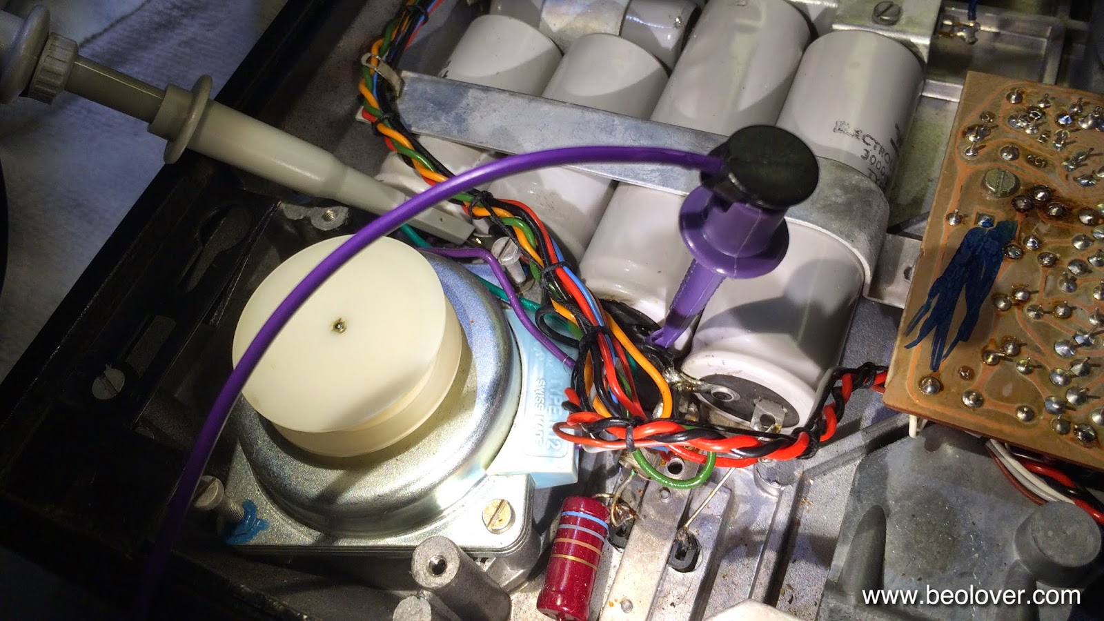
This shows how I hooked up the oscilloscope probe between the 150uF unipolar phase shift capacitor for the 2nd phase of the motor and the 4000uF coupling capacitor to the motor drive amplifier (the purple clip makes the GND connection conveniently using the negative pads of the 3000uF reservoir caps):

The GND connection was made at the negative ends of the 3000uF reservoir caps. This is what I found at 33 RPM:


The RMS voltage was at 7.9V and the signal was clipped. A clear case of overdriving. 45 RPM looked like this: 

Per service manual, the drive is to be adjusted to a RMS voltage of 6.5V at 33 RPM. I switched back to 33 RPM and turned the MOT potentiometer on the main circuit board until I saw a perfect waveform at 6.5V:


I also adjusted the "33" RPM trimmer (to the right of the MOT trimmer) until I got the specced frequency of 42.3 Hz.

An issue of this design is that 45 and 33 RPM have the same MOT trimmer setting but the oscillator puts out different amplitudes. Hence there is a small difference in the drive amplitude at 45 when the adjustment is made at 33:


There is also a small amount of distortion. This can easily be reduced if the drive voltage is reduced a bit to 5.5V:

But of course this results in a too low 33 RPM voltage of only 5.8V RMS at this setting:

I guess the designers elected to live with this small imperfection, since 45 is not so important historically. It also should be noted that the motor runs now very quietly at 45 despite the slight distortion and too low voltage. In light of the new 45 RPM audiophile vinyls, of course, one might consider getting a second 4000 adjusted perfectly for 45 RMP...;-). 


Sunday, April 26, 2015

Beogram 4000: Recapping the PCBs

Today, I exchanged all the electrolytic capacitors on the PCBs of the Beogram 4000 that I am restoring right now. I definitely recommend doing this at this age, since the tantalum capacitors can fail in fiery way when they short circuit. I only use longer lasting 105C types from major Japanese manufacturers. I started out by exchanging the two red tantalum caps on the power supply board. I realized that one of the two screws that holds the board in place is missing, and that the other screw was only barely tight. This could have easily produced an interesting short circuit. I guess I was lucky:
This picture shows the board after replacing the caps, and adding a stainless M3 screw:


On to the main board. There is one added capacitor on the conductor side between the emitter and the base of 1TR22:

After replacement:
The main board also lacked a screw, but since there are four in total, it still was held in place securely. I removed the screws and turned it around. Here is a picture of the original condition. No visible damages to the orange electrolytics (this type often fails at this age, and often one can find them with cracks or leaking):
This picture shows the board after replacing them:

And a detail shot: