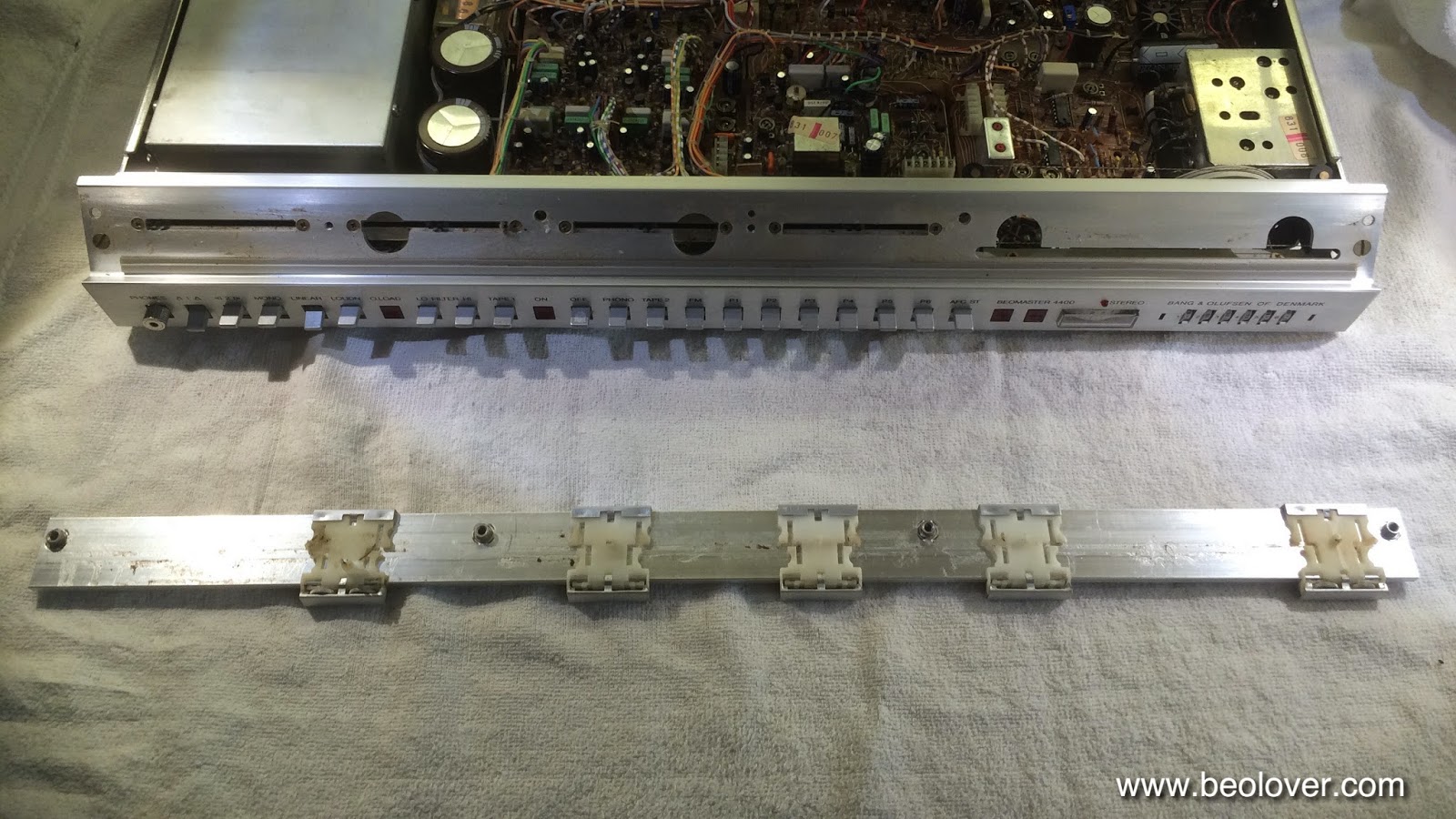
Featured Post

Beolover SyncDrive: DC Platter Motor Replacement for Beogram 4002 and 4004 (Type 551x and 552x)

Late Beogram 4002 and the 4004 (Types 551x and 552x), which have DC platter motors instead of the earlier synchronous AC motors usually suff...

Showing posts with label muting. Show all posts

Thursday, June 26, 2025

Beomaster 2400 (2902): Replacement of Indicator Bulbs with Drop-In Beolover LED Assemblies

Recently I functionally restored a Beomaster 2400 (Type 2902) that I received from a customer in Connecticut. This post discusses the process.

The next step in this project was to design LED replacements for the 15 indicator bulbs that are located beneath the pretty front panel of the Beomaster.

Several of these bulbs function not only as indicator lights, but are functional components of the circuit. In particular the seven program selector bulbs also serve as triggers for the muting circuitry that suppresses the pops during program source changes, like when one changes from Phono to a FM station etc...They produce a voltage spike during the heating up of their filaments when turned on. This spike triggers the muting circuitry of the Beomaster. This means that a burnt out bulb not only ceases to indicate the chosen source, but it also causes loud pops when the user changes to this particular input source.

Therefore, it is desirable replacing the bulbs with LEDs. LEDs last much longer than incandescent bulbs, which burn out 'naturally' after a while as the filaments slowly evaporate when the bulbs are burning. Another advantage of LEDs is that they emit much less heat, and this means the heat-bleaching of the red and green diffusers that cover the bulbs is stopped after LEDs are installed. The LEDs will also alleviate this issue since the replacement boards were designed with red or green LEDs, which do not need color filters in the first place.

This shows the complete set of LED Replacements for Beomaster 1900 and 2400 Indicator Light Bulbs:

The top row shows the two boards for the volume indicator on the left. The three T-shaped boards to the right replace the bulbs that illuminate the balance/treble/bass sliders. The bottom row shows the LED boards for the stereo indicator/program selector/tuning lights board.

Installation:

This shows the stereo indicator/program selector/tuning light board still installed with the colored diffusers in place:
This board is easily removed since it is connected with wire to board connectors that come in from the solder side of the board:
After unplugging the board the filter cabinets assembly can be removed, which reveals the light bulbs underneath:
This photo shows one of the bulbs already replaced with my very first LED replacement prototype. This prototype did not work since I did not understand yet how the muting function is triggered by the program source bulbs. Once I understood that the muting function is triggered by the changing resistance of the bulb filament as its temperature changes during powering up of the bulb I came up with a second prototype that simulated the voltage spike that is generated by this resistance change:
Prototyping is fun!...;-). After a few more iterations I finally arrived at a set of LED assemblies that faithfully maintained the functionality of the bulbs. This shows them together with the PCB with the bulbs removed:
The first step after unsoldering the bulbs is to solder short wire clippings into the solder points of the bulbs:
Here a detail shot:
Once the wire clippings are in place the LED boards can be soldered to them:
A detail picture of some of the program indicators in place:
After replacing the bulbs I verified the proper function of the LED boards. The primary concern of the program indicators is that they properly trigger a short muting period of about 0.5 sec whenever the indicator comes on.
Before I replaced the bulbs I measured the original muting signals. The oscilloscope shot below shows the bulb induced voltage spike across 5R3 (yellow trace) on PCB 5 that holds the bulbs. The blue curve shows the resulting signal at the collector of 3TR29 (3TR6 in the older 2400/1900 versions with 16 step volume control), which indicates that a ~0.5 sec muting period was triggered by the voltage spike:
After replacing the bulbs with my LED boards, I measured this curve:
When the LED board is turned on a voltage spike occurs, which triggers an identical muting period. The main difference is that the voltage spike across 5R3 starts out from a much lower voltage due to the much lower current through the LEDs. This is of no consequence since the muting period is triggered by the spike, which causes the charging of 3C30 (3C6 in the older 16 step volume control versions), which in turn defines the timing of the muting period. A listening test with the new boards confirmed this assessment since program source changes were completely quiet. So all good in the program selector indicator department!

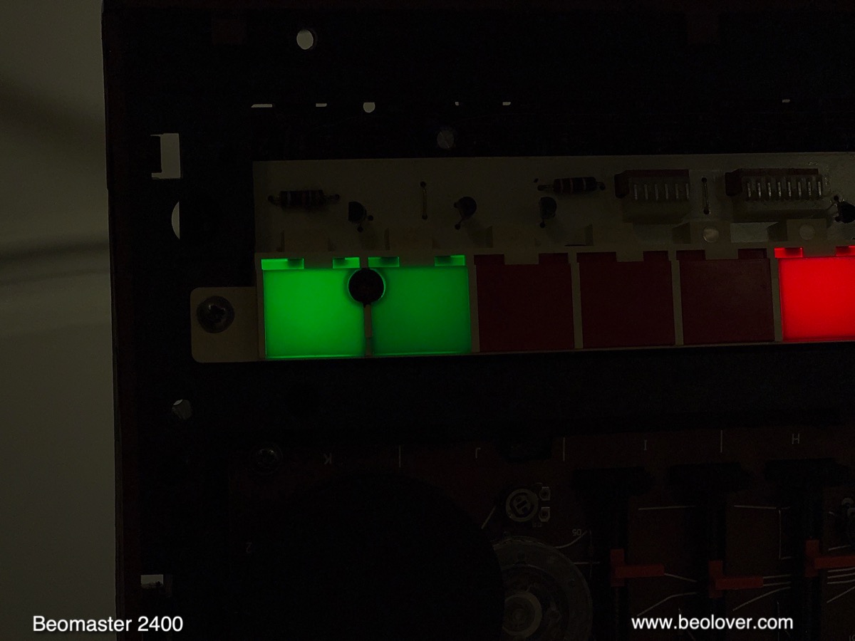
On to the tuning indicators ("balance lights" - they help with centering the tuner on a particular station frequency): These LED boards had to be designed to actually match the current drawn by the bulbs in order to maintain the same behavior during FM station selection. The service manual suggests adjusting the balance between the two indicators whenever work is done on a Beomaster 2400/1900. For this, test point 2TP3 (white grabber) needs to be connected to GND before the trimmer 2R31 (screw driver) can be adjusted:
Before the adjustment the installed LEDs were unevenly lit under this test condition:
Turning the trimmer a bit yielded a symmetrical illumination:
This concluded the installation of the LED boards on PCB 5.

Next came the replacement of the two bulbs in the volume indicator:
This board is connected with three soldered wires, i.e. cannot be unplugged:
It can be left connected for the installation. This shows the two bulbs after removal of the filter cabinets:
I replaced them with two LED boards:
These boards need to be installed in a ~30 degree angle relative to the PCB:
The final task was to replace the three bulbs in the cabinets that illuminate the three sliders:
This board is also soldered directly to wires
and can also be left connected. I forgot to take a picture right after I removed the filter cabinet, so here one that already shows a prototype LED board installed in lieu of one of the bulbs:
For installing the three LED panels the same process is used like for PCB 5. First solder in short wire pieces
and then put the LED panels in place:
And then it was time to do a first test with all the LED boards in place:
Beolovely! 
Then it was time to put this Beomaster back together. But before I did that I installed four new rubber feet. The original ones were all gone:
I installed a set of four rubber feet obtained from the dksoundparts store:
Then I put the enclosure panels back together. This shows the re-assembled unit:
And with the control panel opened up:
The LED bulb replacements look very nice and I would say pretty much indistinguishable from the original bulbs (except that all indicators work again!...;-). I will play this Beomaster a bit more and then it will be time to send it back to its owner.


Monday, July 15, 2019

Beomaster 8000 - Workbench Unit - Investigating FM source audio in the Phono source channel

In this post I wanted to revisit Beolover's fix for reported FM audio crosstalk in the Phono channels.
I actually have been checking for that fault in my Beomaster 8000 restorations and with these new source switching IC device replacements. Unfortunately I had been unsuccessful in replicating the problem.

To review the problem...
Make sure the turntable connected to the Beomaster 8000 does not have a vinyl record ready to play.
When the Beomaster 8000 is switched on from Standby to Phono the Beomaster 8000 volume can be cranked up without hearing any music from the Phono music source.  That is good and is what is expected.

Next switch the Beomaster selected source to an FM station (preferably a strong station). Note the music that is selected. Now switch back to the Phono source (again with no record playing). Turn the Beomaster 8000 volume up and you can begin hearing (faintly) the FM station that you were just on bleeding into the Phono channel.  That is the problem.

As I mentioned, I had not been able to create this problem until this weekend when I moved my workshop Beomaster 8000 unit to a different bench and connected up a powered Terc FM antenna to the radio antenna input. This produced the strongest FM signal I had seen on the Beomaster. Retesting the FM crosstalk problem...I now had reproduced it.

Interestingly this test setup is with my new analog switch devices installed in the Beomaster 8000 preamplifier board. The preamplifier board also has TI OPA2134PA OpAmp devices for all of the analog sources.


Up until now I had reasoned that any audio crosstalk must be occurring in the analog switches the Beomaster 8000 preamp board uses. That made the most sense. However, this preamp board has the new multiplexer switching devices that have very good audio specs and low crosstalk ratings. I thought that should take care of any audio source crosstalk.

It turns out that it doesn't and that is quite surprising...and I do not understand the source of the problem at this point.

An acceptable work around for someone not wanting to make any wiring changes is to always put the Beomaster in Standby mode prior to selecting the Phono source. That will keep the FM tuner in the Beomaster muted while using the Phono source.

We want our cake and eat it too though so I decided to implement Beolover's fix for this problem.

I performed the same wiring modification Beolover came up with but I implemented the change differently.  I wanted to be able to easily switch from the original wiring to the modified wiring.  That option will allow me to keep investigating the problem.

My implementation is to put female jumper connectors on the two wiring routes related to this problem and fix.  Beolover's fix is to run the FM board audio mute control line to the preamplifier board phono source selection line. When Phono is selected on the Beomaster control panel the phono source selection line will tell the FM board to mute the FM audio. When the phono source is deselected the FM control will unmute the FM audio.

Here is the modified wiring for this on the FM board. The picture shows the FM audio mute control line connected to the default path the Beomaster 8000 originally takes.


The yellow wire from the FM board 1R37 resistor can be disconnected from the default ground path and connected to the Preamp board added connector (also on a yellow wire).


This path routes the FM audio mute control line to the preamp board Phono source selection control line.


Testing this modification in the workbench Beomaster 8000 unit I verified that I get no FM audio at all in the Phono channel with I have the FM audio mute control line connected to the preamp board.  I also verified that moving the FM audio mute control line back to the default position re-introduces the FM crosstalk problem.


Friday, February 9, 2018

Beomaster 8000 Circuit Upgrade: FM Audio Muting During Use of Phono Input

After reviving the Beomaster 8000 that came for a visit from Australia with new processor crystals, it was time to do some additional work on it. My customer was annoyed by the crosstalk between FM audio and the phono input while listening to vinyls records, and a solution to alleviate this issue was requested.

Phono inputs are especially susceptible to crosstalk since they are about 100 times more sensitive than regular high level line inputs. The result is that when the phono input is selected (with a player attached or grounded inputs) the FM audio signal can be heard weakly in the background (if a station is dialed in). And that is of course not very Beolovely. The reason for this behavior is a design flaw in the Beomaster circuit: When another input than FM is selected and previously a station was tuned in the FM tuner stays on and continues blasting its signal out to the amplifier board, even though one wants to listen to a record via the phono input.

This diagram shows the solution I developed after a bit of head scratching and downloading the data sheet for the CA3189E IF stage integrated circuit.


The CA3189E chip is responsible for shifting the audio modulation of the FM signal that is received in the front end of the tuner to a lower frequency and amplifying it before the audio signal is then extracted in the detector. The CA3189E was designed with radio applications in mind that do not have a microcontroller at their disposal. The Beomaster mutes the FM audio while tuning between stations to prevent the speakers from emitting loud static noise. It does that by extracting signal strength information from the CA3189E via pins 13 (TP22) and 12, and feeding it into the microcontroller after processing in some additional circuitry. The microcontroller then decides when to ramp the output volume down using the main volume attenuators. 
Alternatively, this chip can do this on its own via its audio mute input (pin 5). The CA3189E data sheet contains a circuit that shows how to do this if you are interested. In the Beomaster 8000 design this pin is simply grounded via R37 to permanently turn the signal output on. 

The circuit on the data sheet in combination with some measurements of the signal strength related output of pin 12 (it seems to be close to 0V between stations and at about 5V with a strong FM station dialed in) suggested that pin 5 could be controlled directly via the microcontroller signal that is fed into the two AD10/278 input selector chips on the preamplifier board. The AD10/278s have three inputs for selecting FM, Tape 2 and Phono. When one selects one of these inputs on the control panel of the Beomaster 8000, the corresponding input goes high (~4.8V), activating that particular signal path on the chips. So my idea was to simply connect the Phono selector line to the audio mute input of the CA3189E via R37 after severing the ground connection of R37 by unsoldering the resistor on the ground facing end. That way, whenever Phono is selected the FM audio muting circuit is automatically activated muting any FM audio in the system that could crosstalk with the phono input.

This shows the practical implementation of this scheme. I elected to make the AD10/278 connector directly at the ribbon cable coming from the microcontroller board. That way the additional connection can be removed from the amplifier board when it needs to be taken out.
I soldered the jumper wire to the plug contacts
and then modified the black cap with a bit of Dremeling to fit over the jumper wire:
Then I wrapped the plug with some electrical tape to keep the jumper wire from moving so it will not break off. This shows the plug plugged in next to one of the AD10/278:
I connected the other end of the jumper to the disconnected end of the R37 resistor after securing it with some shrink tubing to the capacitor located next to it. The solder spot was secured by some additional white shrink tubing:
And then it was time to turn the Beomaster back on. And it seems to work smoothly. FM still works and when Phono is selected there is no more FM audio superimposed. Beolovely!

Thursday, May 21, 2015

Beomaster 4400: Phono Input Muted and AFC Not Working

After I replaced all electrolytic capacitors a preliminary test of the Beomaster 4400 (2419) that I am currently restoring yielded that the phono input would only work intermittently. Further testing revealed that also the automatic frequency control (AFC) did not work. Furthermore, in my first happy excitement I also did not understand that the tuning lights are supposed to be off during non-FM listening, while the signal meter is supposed to be at zero. Both conditions were not met when I switched the unit to Phono.

After some measurements I figured out that the muting function, which should only operate when FM is selected and mute the tuner output in-between stations, came on intermittently, which muted the phono signal resulting in a fluctuating phono experience.

In combination with the lit tuning lights and the non-zeroed signal strength meter, this suggested that the tuner still had an issue. When I started working on this unit, the tuner did not work at all. It turned out that PCB 6 has a crack which prevented the tuning voltages to be applied to the front end. I jumpered the tuning voltage traces on this PCB and thought I was done after the tuner started working. But not so! After consulting the relevant section of the circuit diagram,

I realized that all these problems would occur if the ground connection of the preset and FM switches were disconnected (left center of diagram). This ground connection becomes active when all FM switches are in their off position. In this case, the signal strength meter ("radicator") and the power supply of the tuning lamps (blue dashed box) are turned off via D25 and D18. A look at the PCB schematics

immediately suggested that the crack in the PCB was a bit longer than I had assumed. Since this part of the board is not easily accessible I was not able to assess the damage initially. The black bar in the above picture indicates the approximate location of the crack. It disconnects the GND/black lead from the FM buttons. It is obvious that this also disconnects the AFC switch. This explained why AFC had no impact on the tuning experience (it helps to find the center of the frequency band for a station).

After I realized the extent of the damage and the number of jumpers that would be necessary to fix these issues, it was obvious that the front panel of the Beomaster needed to be removed a bit for better access to the solder points of this PCB.
So I started to disassemble. It is not too difficult an operation to pull the front plate one inch away from the main PCB. This gives enough access to allow some careful soldering activities on this board. The first step is to remove the 'slide rule'. Once it is removed the screws that hold the front panel to the enclosure can be accessed:

Here a detail shot of the small adjustment wheels that are in the volume and FM dial sliders. They come out easily, i.e. one should be careful when removing the slide rule to not lose them:
After that was done and the four screws were removed, the two PCB clamps (pic below shows one of them below the resistor) that hold #6 to the main PCB #5 needed to be pushed through their holes:


After that was done I carefully pried the front panel away from the main board by an inch or so to gain some access to the top of PCB #6:

The picture shows the jumpers installed (red, blue and grey). After the jumpers were in, I gave it a quick test to make sure everything was fixed. It was. So I put everything back together.

Then I hooked the Beogram 4000 up again and put one of my favorite records on: Miles Davis - In a Silent Way. I have the MoFi reissue, which sounds delicious. Unfortunately, while the muting problem was gone, I realized that the two channels were not balanced. The left channel sounded great, but the right channel had very weak bass. Only higher frequencies made it through. This indicated to me that there may be an issue in the RIAA equalization in the phono pre-amp. Oh well, back to the bench for some more testing!


Thursday, May 14, 2015

Beogram 4000: Adjusting the Solenoid and the Switches

Still a few odds and ends to take care of in the Beogram 4000 that I am rebuilding right now. Any complete restoration should include an adjustment of the solenoid and the switches that it controls to specifications. The solenoid not only takes care of the tonearm lifting and lowering, it also actuates three switches that control the audio muting function, the solenoid current (power), and the carriage transport enabling function. The audio muting switches are responsible for grounding the cartridge coils until after the needle has hit the record. The solenoid current limiter is responsible for lowering the current in the solenoid once it is engaged. This prevents the solenoid from overheating while the record is playing and the arm is down for extended periods of time. The carriage transport enable switch enables the servo motor once the arm is down. This prevents accidental carriage motion in case the arm is touched when it is up.

I made a short video that discusses the circuit and shows how to adjust everything to specifications. Enjoy!: