Featured Post

Beolover SyncDrive: DC Platter Motor Replacement for Beogram 4002 and 4004 (Type 551x and 552x)

Late Beogram 4002 and the 4004 (Types 551x and 552x), which have DC platter motors instead of the earlier synchronous AC motors usually suff...

Showing posts with label 69JMBM4400. Show all posts

Friday, June 5, 2015

Beomaster 4400 (2419): Headphones Jack Restoration

I thought I was done with the Beomaster 4400, but I had completely forgotten about the jammed in 3.5 mm headphones adapter:

After removing it it looked like this:

While I was blissfully listening to some nice jazz on the public radio on this lovely Beomaster 4400, it occurred to me that there was something missing. Then it dawned on me that the receiver was lacking its headphones jack bezel. It must have been pushed in when the adapter hit something hard and then went missing after someone opened the Beomaster up to have a look. The headphones jack was also mashed in. Ruffians!:

After taking the jack out it looked like this:

I straightened the jack bracket as good as I could with my vise. In the meantime I obtained a spare bezel. This allowed me to finish up the repair:

With a straightened bracket the jack sits close enough to the bezel to hold it in place from the backside. From the front it looks like this:

Too bad that the banged-in adapter damaged the panel cutout a bit, but I guess for a more than 30 years old unit, this Beomaster is in pretty nice shape nonetheless.
Allright...looks I am finally done! All good in Beomaster land! I really started to like listening to this receiver, but now it is time to ship it back!


Thursday, May 28, 2015

Beomaster 4400 (2419): Missing Preset Cover Replacement

It seems the Beomaster 4400 (2419) that I recently restored runs stable. I have it connected to my Beogram 4002 and I also tested it with the Beocord 9000 that I am working on right now, and everything functions very nicely. The final task was to replace the missing preset cover. There must be a big heap of these lost covers somewhere on this planet, but as long as we do not know where this Preset Cover Shangri-La is, getting authentic reproductions (injection moulded as the originals) from 'Dillen' (beoworld.org) is a great option. He recently sent me a few, and I installed one. Fits very well, maybe a bit tough to remove, but that will keep it (hopefully) away from their hiding place...;-). Here is a pretty shot of the cover:


Time to double box this Beomaster 4400 and send it back to its owner. That is the hard part of Beolove! Constant separation trauma...love can be pain...;-)

Saturday, May 23, 2015

Beomaster 4400: RIAA Equalization - Weak Bass

It seems that the Beomaster 4400 that I am currently restoring is now mostly working. After I bridged all the cracked traces on PCB#6 I finally had a stable Phono input and a working AFC. But then I realized that the right channel Phono input did not yield much in terms of low frequencies and was lower in overall volume compared to the left channel. The tape inputs were working, so this indicated that the RIAA equalization on that channel did not work properly. Here is the relevant part of the circuit diagram:


I added some benchmarks measured on the left channel in the diagram. Input was 10mVpp. This yielded ~3.9V at 100Hz, 900mV at 1kHz, and ~190mV at 10kHz, corresponding to an about 20x drop between 100Hz and 10kHz (=26dB). This conforms with the RIAA curve as shown here (from this very interesting article about different ways to achieve RIAA equalization - another proof that anything can become a complicated topic if one only digs deep enough...;-): 


The red curve is the one that the Phono input needs to achieve. What is coming from the record follows the green curve, i.e. low frequencies are recorded at a much lower volume than high frequencies.
The main reasons for doing this are (1) to increase the playback time and (2) to reduce high frequency noise. Lower frequencies need more space in the groove for the same amplitude output than higher frequencies. This is a consequence of the fact that the current induced in the moving coil of the cartridge is based on the speed at which the iron moves relative to the coil. If one would want to achieve low freq reproduction at the same level as high freqs, the grooves would need to be much wider, which would significantly reduce the play length. By accepting a lower amplitude for low freqs the grooves can be kept narrow and so the record plays longer.
Higher frequencies benefit from being cut at higher amplitudes since that gives a larger signal-to-noise ratio at the upper end of the spectrum. The 'natural' noise of records comes from roughness of the vinyl material, which generates a noise floor. Since during playback the RIAA curve reduces the high frequencies relative to the lower frequencies, the vinyl noise is reduced. This is a similar concept to Dolby NR where low volume sections of the recorded signal are amplified on the tape, and then reduced during playback, which also reduces the tape noise.

Anyway, anything that changes the signal depending on frequency immediately 'smells' like a capacitor issue. The two capacitors in the Phono preamp circuit that are responsible for the RIAA equalization are C105 and C104. And sure enough one of the corresponding units on the right channel circuit, C205, gave me a strange reading. My capacitance meter yielded a fluctuating signal, while C105 yielded a solid 10nF reading.
So I put in two replacements (it is best to do such things in pairs to keep the channels even). Since I did not have 2% tolerance caps available, I went through he batch I had and measured them until I found two that had the exact same value of 10.2nF, i.e were in spec. I soldered them in:


And tested the unit with a 10mV signal on both inputs. The signals were very even on both channels through the entire frequency range. Very good! I put things back together and hooked up the Beogram 4000 that I just restored, and pure bliss! I listened to Autobahn by Kraftwerk on the original German first pressing double album, and all was good! 

While I listened, I decided to explore the topic a bit more and I made a model of the Phono pre-amp in iCircuit (an absolutely great app for spontaneous circuit explorations - not as powerful as a Spice simulator, but so much more pleasant to use - give it a try: iCircuit costs less than a couple high-cal drinks at Starbucks..;-). Here is a screenshot of the model:


The simulation pretty much confirmed the measurements that I made on the 4400 unit. I rearranged the  circuit components a bit to make more clear how this RIAA equalization works.

The voltage divider at the output formed by the three 36.5, 220k, and 470 Ohm resistors and the emitter resistor R103 (330 Ohm) determine the gain of the amplifier via feedback. Without C104 and C105 the gain of the amplifier is ~460 across the entire frequency spectrum, i.e. 10mV at the input generate 4.6V at the output. The RIAA equalization is produced by adding the two capacitors that reduce the 36.5k and 220k resistor values depending on frequency. This reduces the upper end of the voltage divider more and more with increasing frequencies, hence, increasing the feedback and in consequence reducing the gain. This has the effect that the output of the amp is reduced at higher frequencies, and we get the RIAA equalization.

In this context I was wondering about the failure mode of C205. I think it must have partially short circuited the 220k resistor causing a reduction of the base gain of the amplifier. Since this affects the low end more than the high in this circuit, it appeared to the listener (me) as if the low end was missing.

Anyway, this seems to be fixed now! Kraftwerk! Autobahn!


Wir fahr'n fahr'n fahr'n auf der Autobahn
Vor uns liegt ein weites Tal

Wir fahr'n fahr'n fahr'n auf der Autobahn
Vor uns liegt ein weites Tal

Die Sonne scheint mit Glitzerstrahl
Die Fahrbahn ist ein graues Band ...


This is Beolove!


Thursday, May 21, 2015

Beomaster 4400: Phono Input Muted and AFC Not Working

After I replaced all electrolytic capacitors a preliminary test of the Beomaster 4400 (2419) that I am currently restoring yielded that the phono input would only work intermittently. Further testing revealed that also the automatic frequency control (AFC) did not work. Furthermore, in my first happy excitement I also did not understand that the tuning lights are supposed to be off during non-FM listening, while the signal meter is supposed to be at zero. Both conditions were not met when I switched the unit to Phono.

After some measurements I figured out that the muting function, which should only operate when FM is selected and mute the tuner output in-between stations, came on intermittently, which muted the phono signal resulting in a fluctuating phono experience.

In combination with the lit tuning lights and the non-zeroed signal strength meter, this suggested that the tuner still had an issue. When I started working on this unit, the tuner did not work at all. It turned out that PCB 6 has a crack which prevented the tuning voltages to be applied to the front end. I jumpered the tuning voltage traces on this PCB and thought I was done after the tuner started working. But not so! After consulting the relevant section of the circuit diagram,

I realized that all these problems would occur if the ground connection of the preset and FM switches were disconnected (left center of diagram). This ground connection becomes active when all FM switches are in their off position. In this case, the signal strength meter ("radicator") and the power supply of the tuning lamps (blue dashed box) are turned off via D25 and D18. A look at the PCB schematics

immediately suggested that the crack in the PCB was a bit longer than I had assumed. Since this part of the board is not easily accessible I was not able to assess the damage initially. The black bar in the above picture indicates the approximate location of the crack. It disconnects the GND/black lead from the FM buttons. It is obvious that this also disconnects the AFC switch. This explained why AFC had no impact on the tuning experience (it helps to find the center of the frequency band for a station).

After I realized the extent of the damage and the number of jumpers that would be necessary to fix these issues, it was obvious that the front panel of the Beomaster needed to be removed a bit for better access to the solder points of this PCB.
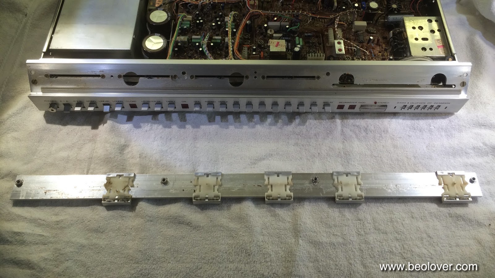
So I started to disassemble. It is not too difficult an operation to pull the front plate one inch away from the main PCB. This gives enough access to allow some careful soldering activities on this board. The first step is to remove the 'slide rule'. Once it is removed the screws that hold the front panel to the enclosure can be accessed:

Here a detail shot of the small adjustment wheels that are in the volume and FM dial sliders. They come out easily, i.e. one should be careful when removing the slide rule to not lose them:
After that was done and the four screws were removed, the two PCB clamps (pic below shows one of them below the resistor) that hold #6 to the main PCB #5 needed to be pushed through their holes:


After that was done I carefully pried the front panel away from the main board by an inch or so to gain some access to the top of PCB #6:

The picture shows the jumpers installed (red, blue and grey). After the jumpers were in, I gave it a quick test to make sure everything was fixed. It was. So I put everything back together.

Then I hooked the Beogram 4000 up again and put one of my favorite records on: Miles Davis - In a Silent Way. I have the MoFi reissue, which sounds delicious. Unfortunately, while the muting problem was gone, I realized that the two channels were not balanced. The left channel sounded great, but the right channel had very weak bass. Only higher frequencies made it through. This indicated to me that there may be an issue in the RIAA equalization in the phono pre-amp. Oh well, back to the bench for some more testing!


Monday, May 18, 2015

Beomaster 4400: Full Recap and Output Trimmer Replacement

Today I completed the replacement of all electrolytic capacitors in the Beomaster 4400 (2419) that I am currently restoring. I also replaced the quiescent current trimmers of the output stages. This is probably the most important item to do in these models due to the design of the output stages. If these trimmers go open circuit due to old age, the output transistors immediately die, i.e. whenever one opens up this model, these trimmers should be replaced and the quiet current adjusted properly.
But first I removed the input/output board that is bolted underneath the main PCB. Here you see it still bolted on:

It is easy to remove it. It is only held with the four screws next to the Tape 1 and Phono jacks. Take the screws out and the board can be removed:

It is connected with one wire-to-board connector to the system, so it is easily taken out. I really like the models they designed after they discovered the existence of such connectors. It makes it so much easier to work on them. The 4400 design is somewhere in between..still a lot of directly soldered connections, which can make id difficult to work on certain areas in these units. Anyway. Here it is taken out:

While I had it out, I decided to do the caps first. So I replaced everything with quality Japanese made 105C types for a long lasting restoration:

The next step was to remove the shield of the power switch. It makes it hard to get to a couple capacitors that are located underneath the switch. I did not want to touch the switch, and it seemed that after removing the shield, there would be enough space to get the task done. This shows the switch as I found it:

And here after unsoldering the resistor and taking the shield out:
Then I replaced all the electrolytic caps on the main board and put in new trimmers. Here some impressions of the original condition:
Left channel and a view on the tone control and preamp section:

And the right channel:

A few capacitors had been already replaced by a previous tech, but he used low grade 85C types, so I decided to bring everything up to 105C spec. Here are a couple pics:

This shows the left channel. I replaced the original single-turn 100 Ohm trimmers with 25 turn cermet trimmers. These are encapsulated and allow a precise adjustment of the quiet current that will remain without drifting over time. My experience shows that regular single turn trimmers can drift through repeated temperature changes, while the worm gear mechanism in a multi-turn trimmer will effectively prevent this, since the gear cannot turn as long as the 'worm' is not turning. This is the left channel:

And here is the right:
The next step was to adjust the quiescent current in both outputs. The manual prescribes to adjust it to 10-15mV across both emitter resistors in the output. The way the resistors were soldered in in this unit, it was more convenient to do the measurement just across one of them, and adjust to 50% of the above range. Here is how I did that:


I prefer to adjust to the lower end of the range, since this will make it run much more cooly. I checked with the oscilloscope, and there was no measurable crossover distortion in this unit with this adjustment.

After all this I fired the unit up and I listened a bit to the radio. It sounded very nice, and the heatsinks stayed very cool. When I received the unit it it ran pretty hot, indicative of misadjusted or problematic trimmers. Even after extended periods of low-volume listening the heat sinks should never get warmer than 30-35C. 
After the radio got boring, I decided to hook up the Beogram 4000 that I recently restored to try out the Phono input. And this was disappointing. It worked briefly, and then started cutting out intermittently on both channels. Still some issues I guess...time to explore the circuit diagram...I always enjoy doing that. This is Beolove!


Saturday, May 16, 2015

Beomaster 4400: Replacing the Main Reservoir Capacitors

Today was output capacitor day in my Beomaster 4400 restoration process. I always enjoy replacing the 'big cans'. It certainly has something satisfying to it. Also, it turned out that this Beomaster definitely needed new ones. It is a fairly painless operation in these units, since the capacitors are only held in place with one clamp, and the grounding wires are well organized on the center bridge of the capacitor assembly. The clamp is even adjustable, i.e. new smaller diameter capacitors can be fitted without the need for adapters. Here is a picture of the original setup:

Here is a shot of the empty bay after removal of the old caps:

This shows the new ones loosely fitted:
After fixing them in place with the clamp it was time to solder them in. I usually use 'helping hands' to hold the wires in place. It is important to insulate the wires from the alligator clamp with some cardboard to avoid them melting through the insulation while the leads get hot during soldering:

And don't forget to put the cable tie back in!..;-). Done:

As usual I measured the old caps, and this ones, while looking o.k. definitely showed signs of their endgame. Their capacitance was out of spec (should be 10,000uF). The 4400 still worked with them, but would have probably shown signs of distortion if played loudly:

On to replacing the remaining electrolytic capacitors in this vintage beauty!


Friday, May 15, 2015

Beomaster 4400: Recapping the FM Decoder PCB

The Beomaster 4400 that I am currently restoring works seems to be nicely now. I listened to it occasionally the last two days, and nothing else came up. So we decided to go ahead and do a recap. Definitely worth doing for this unit due to its excellent cosmetic condition. I already did the IF stage during the trouble shooting process. Today I followed up with the decoder board, that also can be removed. Here are a few pictures:
This shows the board 'in situ':

Taken out. It can be a bit tricky to get this board out since the plastic clamps can be fairly difficult to push through the holes. I usually put a touch of Ballistol around the routed openings in the PCB to ease the strain on the often brittle material:

And after exchanging all electrolytic caps with quality 105C Japanese models:

After this was done, I cleaned the headers on the main PCB and coated them with DeoxIT D100L for long term stability. Then I plugged the board back in and turned the Beomaster on. All good. The reservoir caps are next!


Monday, May 11, 2015

Beomaster 4400 (2419): Tuner Repaired

The Beomaster 4400 that I am rebuilding right now seems to be running on all cylinders again. But a little more work was needed: 

After restoring the 15V rail the tuner came alive, but with a very weak output, while a standard 1Vpp signal piped into the tape input yielded a normal output response. So the problem was definitely not in the amp section. So I poked around on the IF board (#2). First I suspected a broken filter crystal, but the three turned out to be o.k. But while I was messing around out of a sudden the tuner started blasting full volume, indicating another broken trace/bad contact issue. I cleaned the contacts of the two board-to-board connectors and plugged it back in...no change. So I re-soldered all the contacts of the plugs and I also replaced the two electrolytic capacitor on this board with quality Japanese 105C types while I had it out. I also put in new headers and jacks for the signal meter connectors. They looked strangely corroded with some white coating. Here is a picture of the rebuilt board:


After I plugged everything back together the tuner came to life at full volume, but only on the presets. The main FM dial still did not work. This indicated some more contact issues, since the FM dial is nothing but another tuning voltage delivering trimmer in the context of the circuit diagram. Just looks more important...;-). I finally figured out that the culprit was a crack in the switches PCB (#6):

This was a pretty big one. It separated the 4.7V end of the main dial 100k pot from the voltage source, and so the pot was not able to change the tuning voltage from the 26V on the other end, i.e. the tuner was permanently set to 108 MHz independently of the pot setting.

I installed a jumper (grey) to bridge the crack (the grey/white wire goes to the pot):

This brought the FM dial back to life. Then I epoxied the PCB back together using a couple PCB snippets that I had laying around from designing Beogram 4000 scale illumination LED boards:

Here is a nice shot of the tuning indicators after the repair. Both tuning lights work again, and the stereo indicator is on. Beautiful! Beolove!


One the two capacitors that I replaced on the IF board was completely dead. It showed the characteristic cracks in the can, and measured 25nF instead of 4.7uF. This makes this Beomaster 4400 a definite candidate for a recap:


Beomaster 4400 (2419): 15V Rail Restored

I made some progress with trouble shooting the Beomaster 4400 (2419) that I am currently restoring. When turned on, the ON light did not come on, and also no sound from the tuner, but the Tape input worked...Both phenomena suggested that there is a problem with the 15V rail, since the ON bulb is powered via the 15V supply, while the tuner is the main part of the Beomaster that uses 15V. So I started following the 15V traces and wires. They are red throughout, that makes it a bit easier. I started out at C3 and the 15V were present. This meant the voltage regulator was working. I measured the resistance of the ON bulb (6 Ohm), which indicated the bulb is o.k. I finally found the spot where the 15V went lost: A crack in the main PCB (#5) under the Decoder board (#3) at one of the plastic clamps that hold it in place:

Since it is difficult to get directly to the trace at this location, I bridged directly from the power supply at R8. The red wire goes directly to the location after the crack:

This is where it comes out on the other side. I soldered it directly to the red jumper that goes from the main PCB to the PCB that connects the switches (#6):

This improved things:

Now the ON lamp is on and also one of the tuning light came on. However, there are more issues: The tuner only works with the presets and not with the main dial, and the volume is very low. This indicates that there is some issue on one of the tuner boards. Tomorrow is another day...;-)


Sunday, May 10, 2015

Beomaster 4400 (2419): First Contact and a Peek Inside

I recently received a Beomaster 4400 for a checkup and restoration. I took it out of the box and had a first look:

It looks very nice...very little damage to the cabinet and the sliders are fairly pristine. The only thing that was less than beolovely was the headphone adapter jammed through the opening in the front panel doing a bit of minor damage at the opening. And, of course, the presets cover is missing. Luckily, Dillen of Beoworld.org sells authentic replacements, one of which will grace this unit when I am done with it.

The next step was to open it up and have a look before firing it up. I always do this to make sure not to fry the output stages. The 4400 has a similar output topology as the Beomaster 8000 and therefore the quiescent current trimmers are the most crucial parts that need to be checked before turning it on. If they go open contact during transport/due to corrosion, it is the end of the output transistors.
Thankfully the Beomaster 4400 comes with instructions printed on the bottom plate of the enclosure how to open it up:


I removed the bottom plate and then took the cabinet off:

Looks pretty clean. A bit dusty but nothing out of the ordinary. I found a few recently replaced capacitors in the output stages:

Unfortunately, they not only used inferior 85C capacitor types, but more importantly they did not replace the crucial output trimmers (one is visible here right next to the blue cable). Since they are difficult to get at due to a PCB that is mounted below the solder points of the main PCB, I measured the set resistance of the trimmers and then turned them a few times to make sure they would not go open circuit when I turned the Beomaster on the first time. 

After putting them back to the set values (that seemed reasonable based on my experience) I plugged the unit in and turned the radio on. Nothing visible happened. No ON lamp no nothing. Then I plugged in speakers and tried again. There I got a healthy sounding 'bump' when I turned it on again. So something seemed to have powered up. Then I connected my waveform generator to the Tape 1 input, and pumped a 1Vpp/1kHz signal in. And voila, the speakers emitted a pristine signal.
So it appears the tuner has an issue.