Featured Post

Beolover SyncDrive: DC Platter Motor Replacement for Beogram 4002 and 4004 (Type 551x and 552x)

Late Beogram 4002 and the 4004 (Types 551x and 552x), which have DC platter motors instead of the earlier synchronous AC motors usually suff...

Showing posts with label speaker. Show all posts

Wednesday, November 16, 2016

Beomaster 8000: Step Seven - Replacement of the Speaker Switches with Modern Encapsulated Units and Laser Cut Adapter Plates

The final 'standard restoration task' for a Beomaster 8000 is to replace the speaker switches. My own personal statistics are that in about 50% of all Beomaster 8000s these switches will go bad in the near future if they are used regularly, like for headphone listening etc...They are usually corroded on the inside and frequently when a Beomaster is used again after a long period of storage, they break after a few uses and then the outputs are no longer connected to the speaker jacks. This shows the speaker switches flipped out of their 'compartments' for accessing the solder points:

Note the brown PCB-like base plates that hold the contacts...this switch style has long gone out of fashion in favor of fully encapsulated modern designs that are capable of millions of switchings before they need to be replaced. Unfortunately, these modern switches do not have this base board anymore, and hence they do not fit into the compartments under the heatsink cover. I designed laser-cut adapter plates that mimic the original base plates while snugly fitting the footprint of the modern switches:
This shows them after soldering them in:
And situated in their compartments:
All good now in switch land!

Unfortunately, when I gave this Beomaster a subsequent testing of all functions, I realized that the phono jack in the contact box was broken out and also disconnected. Very beo-unlovely! The next post will report about my repair process of these DIN7 jacks.


Tuesday, October 20, 2015

Beomaster 8000: Replacing the Speaker Switches with Modern Encapsulated Units and Laser Cut Adapter Plates

After my second round of output PCB troubles in the Beomaster 8000 that I am restoring right now, I put in new speaker switches. The heatsink cover was still off, so this was a 'good moment'. I implemented modern encapsulated switches and laser cut adapter plates that make them fit into the original bays for the switches. A while ago I made a short video about this process, that also shows the laser cutter in action...what's not to like about digital manufacturing methods!:


These pictures document the procedure on the particular Beomaster 8000 that I am rebuilding. This shows the original switches in place:

Here they are 'folded' out and the original mounting plates are visible:

This shows the original switches in comparison with the new replacements and their adapter plates. Note that the here used most recent design iteration has laser etched tabs on the narrow sides of the plates since I was not able to find plexiglass sheets of the same thickness as the original base plates of the switches:

These switches and adapter plates are available to other enthusiasts, just send me a message.

Here they are soldered in place:
This picture shows them held in place in their bays. The laser cut plates exactly fit in the cutouts and the precisely laser etched thickness of the tabs ensures that the switches are at the right height when the heatsink cover is installed:


Thursday, April 23, 2015

Beomaster 8000: Replacement of the Speaker Switches

The final step of my current Beomaster 8000 restoration was to replace the original speaker switches with new encapsulated ones. Due to the encapsulated construction the new speakers do not have the PCB style base plate that is used in the Beomaster to align them with the small compartments that holds the speaker switches in place. I recently designed some laser cut adapter plates that fit the new switches. More information about this procedure can be found in this blog entry.

Here are a few pictures of this procedure:
This shows the original switches removed from their compartments and turned around:

New switches and adapter plates installed:
And new switches installed in their compartments with the heat sink cover back on:

This concludes the restoration of this Beomaster! Now I will test it for a while in my Beosystem 8000 to make sure there are no loose ends.


Wednesday, October 1, 2014

Beolover 8000: Speaker Switch Replacement with Modern Switches

A fellow B&O fan asked me if my recently developed speaker switch adapter plates for the Beomaster 8000 would be available. I was happy to oblige, but felt like I needed to improve my design a bit for a more satisfying experience. I wanted larger holes for a bit for a better fit of the solder tabs of the switches. I also wanted to cut them from thinner plexiglass to avoid the Dremel step for thinning the tabs for precise fit into the switch compartments of the Beomaster. Another goal was to achieve a press-fit of the adapters onto the PCB board alignment tabs of the switches to avoid the glueing-step to affix the plates to the switches.

Here is a picture of the redesigned adapters with fitted switches (the adapters were cut from 1/16 strain relieved plexiglass):


I also made a video about the process (including a shot of the laser cutter in action - awesome!!..;-). Enjoy!:


Wednesday, September 3, 2014

Beomaster 8000: Standby Issue - Beomaster Does Not Turn Back On During a 50 sec Window

Today I looked into a strange phenomenon I came across in the last Beomaster 8000 I restored. When no speakers are connected, or the speaker switches are in 'off' position, then the Beomaster would not turn on the output stages (i.e. no relay-click audible) if a turn-on occurs in a time window of 10-50 sec after turning it off.

This is not much of an issue in 'normal' operation, where one listens to some music, then turns it off, and comes back an hour later for more. But on the bench, when one tries out a few things and the Beomaster gets turned on and off in quick succession, and often without speakers attached, this phenomenon became quickly apparent.

This is the first Beomaster I encountered with this problem.
So I thought I would try to get to the bottom of this. The first thing is always to do some Googling these days. What came up was a Beoworld.org 'Vintage Products Forum' entry by Dillen/Martin where he states that:

 "It's not uncommon to see that a Beomaster 8000 won't switch the amplifiers back on right after being put into standby. It will light up the displays but not power on the amplifiers.
Put back into standby for 15-20 seconds and it will power up fine again. This is quite normal."

In the particular case discussed here the Beomaster does come on during the first ~10-15 sec, and then not until about 50 sec have passed. After 50 sec it starts up again. The phenomenon is completely reproducible, but the speakers must be disconnected/switched off to experience it. When the speakers are on, everything is fine.

Anyway, I opened it up again today and did a few measurements with my oscilloscope (since this is a transient phenomenon, we need a time dependent measurements...). I fairly quickly identified the cause for the phenomenon: Pretty much the only way to prevent the outputs from turning on in a reproducible fashion is via the fault circuit:


Both right and left channels have a 'fault output' that triggers the 'Fault Switch' on the power supply board to cause a shutdown of the outputs in case a DC voltage is present at the speaker output, or if the temperature in the heat sinks gets too high. In either case a non-zero voltage occurs at the voltage divider between 5R24 and 23 (on the left...that part of the circuit is on the #5 PCBs (output amps), which is used as 'fault output'

I measured the voltage at that R23/24 point depending on the time after shut down with speakers connected. The yellow trace in the scope shot below is the positive 54 V rail which was used to trigger the measurement at 48.8V, i.e. a short while after turning off the Beomaster as the rail started to decay. The blue trace is the voltage at the fault output. So we see that there is a ~600-700 mV negative voltage spike that decays within about 10 sec to zero. This is not enough to trigger the fault switch because of  6R62, and everything is o.k.


An entirely different picture presented itself after disconnecting the speaker from that channel:


Note the now larger 1V scale for the blue trace, i.e. the initially still present small negative voltage spike seen with speakers connected in the scope shot above was completely overwhelmed by a ~4V positive potential when the speaker was disconnected. This potential boost was reset after about 45 sec and zero voltage remained at the fault switch at that point. This corresponds nicely with the ~50sec I measured that I had to wait to get the Beomaster to turn on again. It seems that after 50sec everything resets. This correlates with the delay when the microprocessor turns off the 15 V rails after shut down has been initiated.

It may be that there is a potential build up due to an inconsistency in the decays of the positive and negative 54V rails after turning the Beomaster off. This is no problem as long as there is a speaker connected, which provides a path to ground if there is some DC transient on the output during shutdown. Without speaker, the potential builds up, and the fault switch is triggered.

The real question is: Why do only some Beomasters exhibit this phenomenon, while others do not. I am aiming to do similar measurements on one that does not show this phenomenon, maybe we can learn something from that...

Saturday, August 30, 2014

Beomaster 8000: Replacement of Speaker Switches - Laser Cut Plexiglass Switch Adapters

I always replace the speaker switches when I restore a Beomaster 8000. They are often corroded, and I experienced several failures in my own Beomasters (I often use my Sennheiser RS180s, and therefore need to switch the speakers on and off fairly frequently...). The issue with these switches is that the original model was designed with a high density board base, which had installation guide tabs on the side. The Beomaster housing is designed with bays that fit these tabs exactly. All new switches seem to be fully enclosed in plastic. While the general form factor is still available, in the past I had to extract the high density boards from the old switches, modify them with a Dremel, and then glue them to the bottom of the new switches. See this post for the original procedure:


I never really liked the Dremel job...not precise enough for my taste. Recently, I learned to operate a laser cutter. What better first project than designing a nice adapter plate, which would align the new switches precisely to their compartments??

I cut the adapter platelets from 5/64 plexiglass (this is a bit too thick, but that is all I had at that point). That meant I still had to put the Dremel to them to reduce the thickness of the tab areas to about 3/64, the thickness of the high density board. If I do it again, I will cut the entire adapter board from 3/64 plexi or something similar. This shows the new switches in comparison with one of the old ones and the laser cut adapters. Note the slits, the board mounting guides of the switches fit snugly into them, aligning the switch (BTW: I used No.: 611-S201031MS02Q from Mouser) with the adapters.


Here after glueing the adapters to the switches and Dremeling the tabs thinner:


Here are a few pictures from the installation process:

Original switches removed from their compartments for desoldering:


New switches installed (it surprised me how durable the plexiglass was during soldering...no issues with melting, warping etc...):


In their compartments:


And with heat sink cover installed:


Perfect!! These new switches are much smoother than the old ones and are guaranteed for a few million switchings! On to the display board!

Monday, June 16, 2014

Beomaster 8000: Replacing the Speaker Switches

Time for the Beomaster 8000 speaker switches while the heat sink cover is off. Another 'standard rebuilding task'. These switches are corroded in most 8000 units, and when used consistently will fail soon. I often switch between headphone and normal speaker operation, and these switches failed in all three of my personal 8000s after a few dozens switchings. Hence, they must go. Luckily, there are almost identically looking modern encapsulated replacements available. See here for more details on part numbers etc...:

http://beolover.blogspot.com/2011/10/beomaster-8000-speaker-switch-repair.html

I used pretty much the same procedure in the current restoration project, except that I directly drilled holes into the base plates, instead of messing with the Dremel tool...can't beat experience! Here are some pics:

Original switches from bottom:


After I removed the bottom plates from the old switches and drilled holes into them to permit the pins of the new switches to protrude:


After glueing them together. This establishes the original form factor that they fit into their compartments:


After soldering them in:


And in their compartments: Like it never happened...;-)!


The control panel is next! Slightly dicey affair due to the often cracked plastic receptacles for the screws, and the buttons and sliders that need to be refitted in their proper places during re-assembly. I always wish I had four hands to do that!


Sunday, March 2, 2014

Beomaster 8000: Speaker Switch Replacement

Further inspection of the Beomaster 8000 yielded difficult to switch speaker switches. As in most 8000s of this vintage these switches are corroded and most fail within a short time if used consistently. We decided that the switches needed to be replaced with new ones. Here a couple pics of the old ones:

and bottom view:


Unfortunately these switches are not made anymore. Technology has progressed, enabling fully enclosed plastic packages. To fit new switches to the compartments of the Beomaster 8000, the old-style PCBs that formed the bottoms of the old switches need to be transferred to the new ones. I took the old switches apart by Dremeling the plastic 'buttons' off that hold the PCBs to the plastic  enclosures, and drilled holes into them to allow the pins of the new switches to protrude:


Then I glued the PCBs to the new switches:


And the final product:


Time to solder them in:


And installed in the 'compartments':


Testing yielded a smooth operation. Much better than the old ones! Time to give the Beomaster 8000 a spin!

Wednesday, September 5, 2012

Beovox 4500 Re-Assembled

I re-assembled the Beovox 4500s...below is a picture of the right speaker. Beautiful! Communication with the Beosound 9000 through Power Link works also very well. I used "Din 8 (Large Din) 8 pin Male-Male" cables for the Power Link connection. The so-called original (overpriced) Power Link cables that are available on ebay are nothing else. This is the beauty of this set-up. The speakers are connected to the receiver by a data bus and 2V audio signals only, i.e. all that is needed is a shielded 8-pin small signal cable. The amplifiers run on their own power - each speaker has its own power supply and an integrated amplifier. I connected my ipad on the 9000's auxiliary input (selectable through "ATape" on the Beo 4 remote) for testing. Need to get a 75 Ohm FM antenna to get the tuner working. And burn some CDs that I can use the CD changer...how very vintage!...;-)

Monday, September 3, 2012

Beolab 4500: Panel Polishing (2)

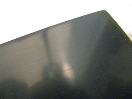
Today, I did the vinyl panel of the right Beovox 4500 speaker. Experience matters. Yersterday, I did not dry the panel after each step before inspection. This resulted in some missed scratches that consequently were not polished out in subsequent steps. Today I made sure to dry the panel with a soft cloth after each step and then give it a thorough inspection. This resulted in a more consistent polish. Here are some detail pictures before and after each polishing step. One can clearly see the alternation between horizontal and vertical patterns until the 4000 grit Micro-Mesh, after which a uniform shine develops.

1) Damage detail (these scratches were easily felt with a finger tip):


2) 220 grit


3) 400 grit


4) Micromesh 1500

5) Micromesh 1800

6) Micromesh 2400

7) Micromesh 3600

8) Micromesh 4000

9) Micromesh 6000

10) Microgloss polish paste - done!

After this I thought I were done, but unfortunately I had to discover that the transformer in one of the amplifiers sheared off its mounts...this probably happened during transport. The fairly heavy transformers are only held in place with four fairly small screws bolted into thin extruded plastic tubes attached to the amplifier housing...another example for B&O's sometimes weak internal designs...let's see what some superglue can do (luckily the broken off parts were all present...).


Beolab 4500 Speakers: Polishing of Plastic Panels

No soldering today. I thought it is finally time to work a bit on my recently obtained Beolab 4500 active speakers. They came from ebay where they were listed as non-working. While they turned out to be working after all, they had badly scratched plastic panels and one significant scratch on one of the aluminum panels. While I am not sure what to do about the aluminum panel, the plastic panels can be easily fixed. Last year I polished the dust cover of a Beogram 4004 to a pretty new looking state. I used the amazing Micro-Mesh KR-70 polishing set, which consists of a rubbery polishing block and a series of fine grit sandpaper. Following the instructions that came with the kit allowed me to fully restore the 4004 cover.

Today, I used this kit on the Beolab 4500 panels. Taking the panels off from the amplifier part of the speakers is pretty simple, but one needs to pay attention that some pretty thin and short cables that are attached between the panel and the amplifier chassis. Hence, after removing the torx screws, carefully lifting off the panel and removing of the plug on the display board and the complete input switch board are required to get the panel off.

Before polishing I also removed the display board from the panel. Since the polishing process involves the use of water, it is best to protect the display board. I also covered the brushed aluminum coated part of the panel with bubble wrap to protect its surface during the polishing process. Here is a pic:


This pic shows a close-up of one damaged area:

When the damage is so deep that one can feel it while moving a finger across, the Micro-Mesh manual prescribes to start with standard 220 grit sand paper from a hardware store. Now, this type of paper is common for wood working, i.e. it is pretty coarse. When I did this the first time I was very reluctant to put this grit to work. Essentially, it dulls the surface completely - a scary moment for the Beolover...;-). Here is a picture after I worked the panel with the 220:


Looks pretty 'woody' doesn't it? This step is probably the most important step of the entire polishing process. With the 220 basically the surface is removed to a depth of the deepest damage. In other words the 220 needs to be worked in an even parallel stroke across the surface (and sides of the panel) until the only scratches present are those from the 220 grit. This means all scratches need to be in the direction of the stroke, and the entire surface needs to be completely homogeneously scratched.

The following steps are basically to use ever finer grit, and apply each grit level with strokes that are 90deg off relative to the stroke used for the previous grit. This allows to see the moment when the scratches from the previous grit are replaced by scratches from the current (finer) grit (dry the surface and look at it against a light source - if you see 90deg off scratches keep at it until they are gone). Successively, with each step, the scratches get more shallow, until they become invisible. That is the moment when the surface is fully reflective and shiny.

Here are a series of pics from this process:

After 400 grit:

After Micro-Mesh 1800:


After Micro-Mesh 2400:

After Micro-Mesh 3600:

After Micro-Mesh 4000 (it starts getting shiny):


After Micro-Mesh 6000 (very nice! almost as new!):


After Micro-Gloss polishing fluid:

That's it!! 
In summary, the most important aspect is that after each step all scratches from the previous level must be gone, and that only scratches from the current grit are left. If the previous scratches are not completely removed, it will be impossible to get them during subsequent steps, since the grit gets ever finer, and does not have enough 'power' to remove deeper scratches from coarser, previous, grits.
One more panel to go! Can't wait to hook these elegant beauties up to my Beosound 9000!!