Featured Post

Beolover SyncDrive: DC Platter Motor Replacement for Beogram 4002 and 4004 (Type 551x and 552x)

Late Beogram 4002 and the 4004 (Types 551x and 552x), which have DC platter motors instead of the earlier synchronous AC motors usually suff...

Showing posts with label circuit. Show all posts

Friday, February 21, 2025

Beogram 4000: A New Arrival from Australia - First Look and a Fun Evening Finding a Short in the 6V System

I recently received a Beogram 4000 from a Co-Beolover in Australia for a functional restoration. This shows the unit as received:

Sadly, the keypads were not taped down and so the big one in the center liberated itself on the way. Luckily, soon after it found a safe spot in the guts of the deck where it remained for the rest of the trip.
On the way to its safe spot it made a few small marks on the surrounding aluminum surfaces:
Over all, this Beogram got off lightly from this episode. I have seen units where such awol keys can create a lot of dings. One thing that saved this one is that there was a foam piece under the hood as I show in my packaging video. This reduced the available pathways for this key considerably.
So not too bad. Actually, this deck still looks fairly good with a nice platter (only a few dings on the rim, probably from earlier transportation without locking the transport locks): 
I removed the aluminum panels and the platter and had a look below deck:
Immediately, some 'beautiful' work on the reservoir and motor capacitors became apparent!...;-):
I also found an earlier version of the Beolover Tracking Sensor LED Light Source for Beogram 4000 implemented:
There was also already a new carriage pulley installed:
One of the 'problem areas' of the Beogram 4000 is the awesome position indicator that shows where the needle is on the platter. This indicator has a fragile red plastic part that often gets damaged. I always remove this assembly when I work on a Beogram 4000 to lessen the likelihood for damaging it:
Often the very thin end breaks off when the assembly is removed by inexperienced operators. The thin end is the actual indicator that sticks deeply into the keypad cluster, and so can be broken off easily. In this case, however, the small plastic tab that holds the red plastic part on the metal assembly so it can slide forth and back as the carriage moves had broken off:
I am thinking how to fix this. Maybe a small 3D printed part that can be epoxied on.

After this visual inspection, I re-installed the keypad keys, switched the voltage selector to 110V and plugged it in. I pressed ON and the platter motor started rotating, but otherwise all functions were dead. None of the keys had any effect. No light from the sensor arm either.

This immediately suggested an issue with the 6V system, which powers the early-days hard-wired digital control logic (the 'brains' - one of the exciting aspects of this design!...;-) and part of the analog 'executive' control system of the deck.

I examined the power supply PCB and found a non-standard 500mA/T fuse installed that was blown.
I unsoldered the fuse and measured the signal between the two blue wires that connect to the 6V secondary of the transformer:
This is the trace I measured:
About 32V peak to peak AC. This is about what one would expect. This translates into about 11V RMS, which then is converted by the old-fashioned analog voltage regulator and a 2200uF capacitance into a stable 6V rail.
The presence of the proper input voltage and the blown fuse suggested a short in the 6V system. And indeed when I measured the resistance from the 6V reed relay output to GND I saw essentially 0 Ohm:
This suggested a direct short somewhere in the 6V system. Previously, I had never fully explored the 6V system on the Beogram 4000. It turned out to be a bit of a 'can of worms' with many yellow wires going to solder points on the main and keypad PCBs. This gets even more complicated since a lot of these wires go forth and back on the boards themselves to bridge circuit traces on the old single layer boards, as well as between the boards to complete circuits. This messy design is a consequence of the limited manufacturing techniques for electronic circuits of the early 1970s, which made such connections necessary.
This left basically only one option for isolating the problem: Unsolder all yellow wires one-by-one and keep an eye on the resistance between 6V rail and GND:
Even the solenoid transistor is connected to a yellow wire (which has nothing to do with the 6V system - I guess they ran out of wire colors...;-). I replaced the transistor anyway during my odyssey through the deck, just to make sure there was no additional source of short circuit (they often go bad due and I always replace them when I restore a Beogram). This shows the original transistor soldered in:
And after installing a modern TIP41C that has a higher voltage tolerance, which is advantageous for its battle with the solenoid sparks:
After a while I finally isolated the short circuit to be somewhere on the sensor arm assembly. Its light bulb is powered by the 6V system and, yes, there is a yellow wire going into the sensor arm assembly!

My measurements led me straight towards the sensor arm tube itself. And indeed this is where I finally found the short:

The person who worked on this deck apparently removed the sensor arm, probably due to a stuck damper to arm linkage, whose pivot point can only be re-lubricated when the sensor arm assembly is liberated. I think he removed the actual sensor arm tube when he tried to get the linkage out, which is usually obstructed by the sensor wiring. Then, when he put the arm assembly back together, he mistakenly installed one of the spiky lock washers that are used for securing the arm assembly to the carriage under the screw that holds the sensor arm tube to the assembly. In this process he managed to get the yellow wire caught by the spiky lock washer, which duly pierced the insulation:
This made me remember a formative moment of my late adolescence, when I brought my first car (a 1969 Renault 4 with 26HP and a 6V battery system...;-) to a mechanic due to a clogged up carburetor. When I asked 'how much', he said, "100 Deutschmark if you let me do it right away, and 200 DM if you try it first yourself"...;-). Sometimes it is just a good idea to let the experts take over. It saves everybody a lot of time.
I set out to fix the damage. This required unsoldering the end of the yellow wire from the carriage PCB and pulling it out so I could install a stretch of shrink tubing:
This shows the shrink tubing installed:
While I had everything apart I also removed the damper to arm linkage and put some synthetic grease on the pivot:
A slight tug on the small copper plate that is glued to the sensor arm assembly to facilitate lateral tonearm movement when the arm is up made it fall off:
I cleaned off the deteriorated double sided tape and epoxied it back into place:
Then I put everything back together.
I installed a new proper spec 400mA/T fuse in the secondary transformer circuit:
I also replaced the 6V regulator power transistor and the two electrolytic capacitors that are on the power supply board. This shows everything back in place:
Before I plugged the unit in I measured the resistance to GND at the output of the 6V reed relay for the record:
I guess when everything is o.k. one should see around 30 Ohms. Most of this current path is caused by the light bulb in the sensor arm. 
I plugged the unit in and pressed ON. Now the sensor arm light came on and I was able to move the carriage left and right and also could activate the solenoid. Life signs!...;-).
Now comes the main part of the restoration! Stay tuned.


Saturday, March 25, 2023

Beogram 4000: Platter Motor Stopped Working

Last year I restored a Beogram 4000 from a customer in the UK. Unfortunately, he recently contact me since the platter motor stopped working. 

After receiving the unit I put it on the bench and started looking into the issue. first I checked the power rails and the reed relays. Everything tested fine. The next step was verifying the motor signal. I measured at the motor capacitor, and there indeed was no signal.

So I did the classic 'follow the signal' approach. I measured the oscillator signal at the collector of TR8, which checked out o.k.: 

The oscillation is not a perfect sine wave, since I had to replace the light bulb in the Wien oscillator with diodes when I restored it last year.  But so far so good...now I measured at the base of TR9, which should essentially show the same signal, just shifted to zero V since it is coupled via C6 to loose the DC component. But the signal was gone:
So it had to vanish somewhere between TR8 and TR9. I measured all the connections between TR8 and TR9, and it turned out that the signal vanished after the motor trimmer VR3. I replaced VR3 with a modern 5k 25 turn trimmer, but no cigar! The signal was still gone after the trimmer. At that point it dawned on me that there must be a short to GND somewhere. A closer inspection of the board yielded this:
R24 and R20 were touching! Something had bent the two resistors together, which effectively connected the base of TR9 to GND. I bent the resistors apart, and voila: The motor signal returned. This is the 33 RPM trace
and here is the 45 RPM.
So the trimmer had been replaced unnecessarily. This shows the new unit peeking through the access hole in the PCB for adjusting the motor voltage:
I put the platter on and a cartridge to see if I could play a record successfully. But the arm did not lower on the record. I realized that the sensor arm was dark, i.e. no power to the LED light source I had installed last year. I measured the voltage at the LED and it turned out that it was 0V. So I looked for interruptions in the connections between the PCB and the LED. And quickly I found the culprit: The yellow wire that connects 6V to the carriage had broken off its terminal on the PCB:
I soldered it back on, and now the deck is playing beautifully again! I will play a few more records, and then it should be time to travel back to the UK.


Sunday, June 7, 2020

Beogram 4000: A Fun Evening with a Prematurely Activating Solenoid

I am making good progress with the Beogram 4000 that I recently started to work on. After rebuilding most of the deck, I finally plugged it in for the first time and started it up. The carriage started moving in search of the LP setdown point. It found it and stopped, but then nothing. No solenoid activation to lower the arm. I performed a visual inspection of the wire harness and the solenoid transistor 0TR4, which is mounted directly to the enclosure bottom in search of heat transfer. I immediately saw that a thin grey wire had come off from one of the terminals of the SK3054 NPN power transistor (later models usually seem to have a TIP41 in this position):
An interesting question at this point was, however, to which terminal should it be connected. I did a bit of contact tracing and comparing with the schematic in the manual:
It turned out that the emitter of 0TR4 has three wires connected, a yellow one creating a feedback to the base of the initial control transistor 1TR10, a black one to the current limiting resistor 7R1, and a thin grey one to the switch that short circuits 7R1 during initial activation of the solenoid. This explained the non-action of the solenoid at the LP setdown point: If the solenoid is not connected directly through ground via the grey wire during the initial lowering of the arm, not enough current flows and the solenoid is not strong enough to act against the springs in the arm lowering mechanism. I reattached the grey wire to the emitter,
which restored the solenoid function. So far so good.

Unfortunately, I immediately realized when I tried out starting the unit that the solenoid now briefly activated right after pressing the ON key. After this brief 'twitch' of the solenoid everything proceeded normally. The arm stayed up and at the LP point it was lowered.

First I thought there was a start-up delay issue with the delay circuit that sets the flip-flops in the logic control circuit when the unit is powered up after ON is pressed. But a check of the Q1' signal with the oscilloscope revealed a normal behavior:
The yellow trace shows the Q1' logic signal, and the blue trace shows the signal at the base of 1TR20, which is responsible for generating a short delay to set the flip-flops to the proper start states. The yellow trace essentially confirms that the Q1' signal that controls the solenoid is indeed going 'high' when the ON key is pressed, i.e. the solenoid should not twitch as far as the logic circuit is concerned.

After a bit of head scratching it occurred to me that the fault most likely was within the solenoid circuit itself. So I measured the signal at the base and the collector of 1TR10, in an attempt to follow the execution of the Q1' 'command'. This shows the traces I measured:
The blue trace is the signal at the base of 1TR10 and the yellow at the collector. This explained the behavior. The collector only sluggishly follows the signal at the base. The base signal turns the transistor on, but the voltage at the collector only collapses over about 30 ms, in effect creating a situation that for a brief moment is able to turn on 1TR11, and with that 0TR4, and so the solenoid gets a brief current boost, which made it twitch. After the 30 ms the signal is close to 0V, and the solenoid turns off.
I had a closer look at 1TR10, and the flux residue on its solder points already suggested that some previous intervention had taken place:
I flipped the board around and found this transistor installed:
Clearly a non-spec type, a SK3122. The manual prescribes a BC239B and a few alternate BC types. I pulled the data sheet for the SK3122, and it suggested, however, that this type should be ok for this circuit. But when I checked it with my transistor tester, it turned out that its hFE gain value was too low:
It should be at least 120 according to the data sheet. Out of spec gain seems to be an increasingly common issue with small transistors of this vintage.
I replaced it with a new 1N2222 with an hFE of 210, and this fixed the issue. No more twitching of the solenoid after pressing start. Out of curiosity, I measured the collector signal at 1TR10 with the oscilloscope, and indeed the reaction of the collector signal was now much more swift:

So it seems this Beogram has a working solenoid circuit again!


Saturday, April 7, 2018

Beogram 4000: An Entertaining Afternoon Exploring the Record Detection Circuit

While exploring an issue with the differential stop circuit of the Beogram 4000 that I recently finished restoring, I noticed another strange issue: While record detection worked at the 12" (LP) set down point, it often failed at the 7" (singles) point, i.e. when starting the deck without a record on the platter, it would pass by the LP point, but then set down at the singles point.

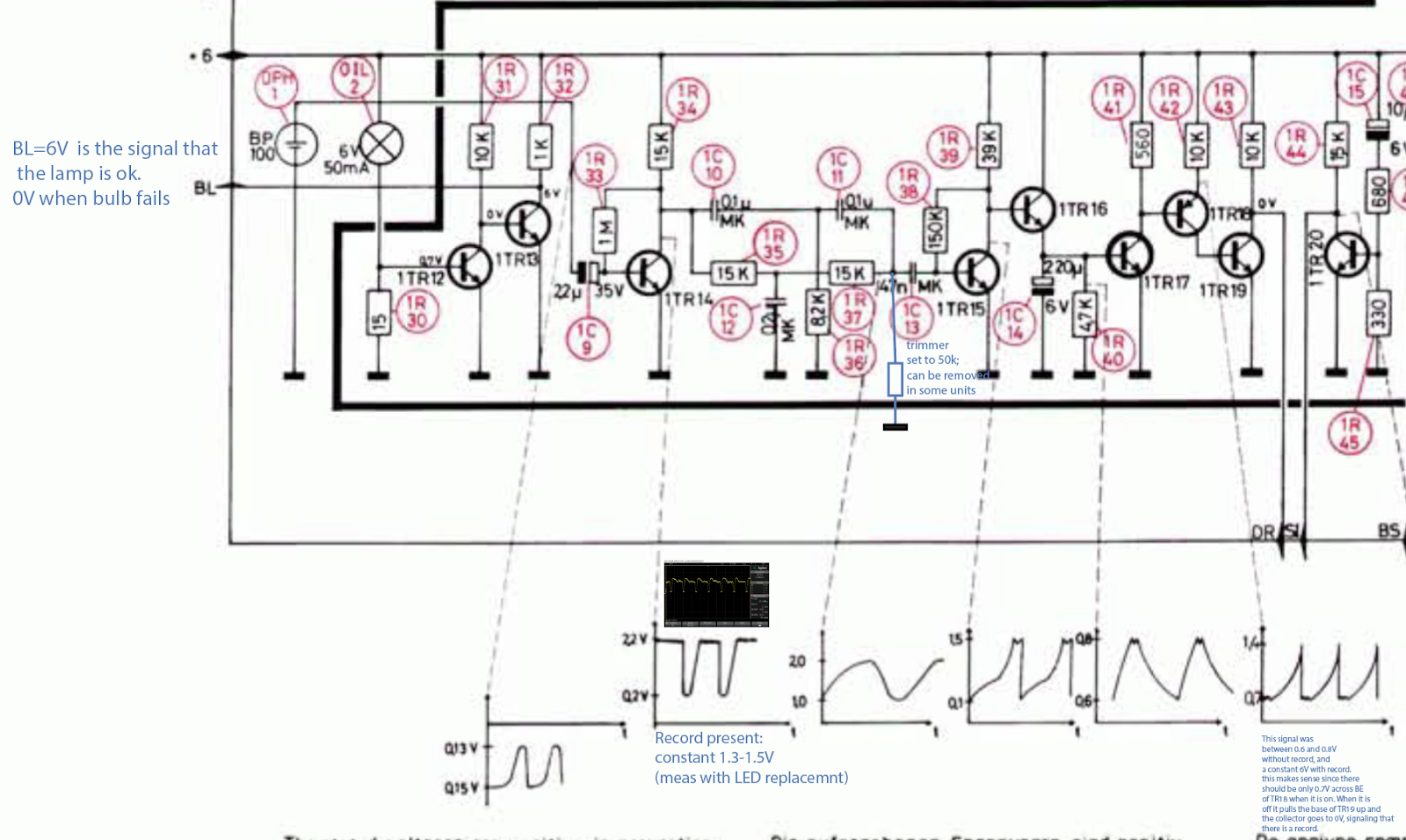
But let's first have a look at the circuit diagram: This shows the relevant section covering the detection system:


The sensor signal from BP100 on the left is fed into the base of TR14 via C9. TR14 provides an initial amplification of the weak sensor signal that then is processed further into a digital output signal for the control system. The signal is filtered in a RC network and fed through TR15,16,17,18 which essentially provide current and signal inversion resulting in a digital output signal from the collector of TR19, which is the "DR" input to the control logic in the keypad. DR is 6V if a record is present and 0V if there is no record on the platter. 
So the first step of my investigation was to measure IN and OUT signals of the circuit to see if the issue is in the circuit (and not in the control logic). This is what I got:
The green trace is the amplified sensor signal at TR14. We see the usual oscillation as the ribs on the platter pass underneath the sensor. These oscillations are as specified (~0.2-2.2V), i.e. my LED replacement of the light bulb was still working fine (as expected!...;-). The yellow graph is the DR signal. We see that in the beginning as the sensor arm passes the small gap between home position and platter the signal is 6V as it should be (the gap has no ribs, i.e. it looks like a record to the detection system). Then, when the oscillations start on the green curve (sensor is now over the platter), there are a few strange oscillations in the DR signal before it settles into the prescribed 0V indicating that there indeed is no record. However, as the carriage travels further in, these oscillations start again and then even temporarily give way to a constant 6V stretch before the oscillation starts again. Absolutely not like it should be! When everything works properly the yellow signal stays solidly at 0V until the carriage returns home. 
After having a bit of a think I concluded that TR19 was not providing enough current to the three logic gates that are fed with the DR signal. From the FHC131 datasheet I learned that these ancient gates take an impressive 2 mA per input when they are pulled low. So it seemed that TR19 was not fully on, causing its collector to drift towards 6V. The oscillation is probably a result of the fact that when CE goes high resistance, the BE current is concurrently reduced allowing the voltage from the (feeding) transistor TR18 to recover until the process starts anew.
After this illuminating moment I wondered about the root cause of this issue. Often one can find circuit problems by simply looking at the circuit to see anomalies like heat traces or the like. In this case my eye fell on the strange trimmer that one finds soldered to the main board on the solder side in most Beogram 4000s:
It is not on the circuit diagram. It is a 50k trimmer that connects R37/C13 to GND (I added it to the above diagram in blue). I checked the four 4000s that I have currently around, and their trimmers were all set to the maximum 50k value...somehow this suggested that whoever adjusted them seemed not to think much of them, trying to reduce their current draw as much as possible. At this point I am a bit mystified why the trimmer was added as an afterthought by the designers...there must have been some issue with the circuit under some circumstances, maybe a parts tolerance issue.

Anyway, experimentation and hunches often yield a fix and so I hooked up the oscilloscope to the collector of TR15 and measured with and without the trimmer connected. Disappointingly the curves looked very similar like this:
About what the diagram above suggested. This frustrated me a bit, but there was no stopping at this point and I marched on, connecting the oscilloscope to the collector of TR18, which feeds the base of TR19, i.e. if TR19 has trouble staying on while delivering 6 mA, there needs to be a difference in the TR18 output. And bingo, the trimmer made a big difference there. This is the signal with trimmer:
We see big spikes towards 6V, while the diagram suggests spikes no larger than 1.4V. I took the trimmer out and measured this:
Very small spikes, meaning that in this case TR19 was basically permanently on since TR18 stays fully on, i.e. TR19 should have no trouble providing 6 mA into the gates of the control system. And indeed, with the trimmer gone, the 4000 record detection mechanism started working very reliably. So the lesson learned here is to not only check the signal at TR14, but also at TR18/19 to make sure that the DR signal is stable. Alright, time to enjoy another record one this lovely Beogram 4000! Let's see if that was the last act of this eventful restoration.

**************************Note added in proof***************************************
The great Dillen of Beoworld.org sent me a message after I posted this. He indicated that this trimmer was added to the 4000 circuit as a way to adjust the sensitivity of the circuit due to the advent of transparent vinyl records. If there is a transparent record, the ribs of the platter are visible to the sensor at varying 'contrast' depending on the color and widely varying translucency of such records.
So I went ahead and experimented a bit more using a translucent red and completely clear record. This particular Beogram 4000 was able to detect both without any ambiguity with trimmer absent. 
However, this does not mean that this is the case for all Beogram 4000s, since the sensor circuit is designed with analog amplification stages that are biased using a single BC resistor. This makes the gain dependent on the individual current gain value (Hfa) of each transistor, which can vary significantly, even if the transistors are from the same production run. So this issue is something to keep in mind when working on the 4000 and a verification of proper detection of clear records should be part of the 'standard restoration repertoire'. The joyful exploration of analog control systems continues!..;-)


Thursday, April 5, 2018

Beogram 4000: An Entertaining Evening Exploring the Differential Stop Circuit

Before we send a restored unit back to a customer, we always give them a good 'real world' test, where we simply play a bunch of lovely music over a couple weeks and observe if everything works consistently. The listening part is of course part of the fun of Beoloving! There is always music in the work shop! The case of a recently restored Beogram 4000 is a proof in point of the usefulness of such testing phases: While playing a number of records, I noticed that occasionally the arm would not return to the home position once the end groove had been reached. Normally, the Beogram 4000 detects the end groove spiral due to the higher speed of the carriage and then lifts the arm and returns the carriage. Not in this case, though, where the needle simply went all the way in and then kept playing the final turn over and over again...tock...tock...tock...not very Beolovely!

The problem was that this would only happen occasionally, but most times everything would be fine. Such problems are hard to troubleshoot. In the beginning I thought it was simply a MV switch issue (most 4000 issues come from not working switches), but since I had coated the switch terminals with gold, tests demonstrated that the switch was working very reliably. So I concluded the problem must be in the differential stop circuit, which produces the logic DS level that tells the control system that it is time to lift the arm and return the carriage home. This shows the relevant part of the Beogram 4000 circuit:


This is how it works: The detection of the end groove is done via the carriage motor voltage. Since the end groove typically makes the carriage move faster, the motor voltage is larger than during normal play back of a track. That is why the circuit is called Differential Stop (DS), the end groove is not determined by the position of the arm, but by its velocity towards the center of the record. One of the issues is that the arms do not only move faster in the end groove, but also between tracks and in the run in groove at the outer rim of the record. This problem is solved by introducing a carriage activated switch ("MV") that enables the DS circuit only close to the end groove region of the record. This switch is on the second circuit diagram of the 4000 and it connects MV and MV' in the above circuit snippet.
So when the carriage reaches a point about 65mm away from the center of the record MV and MV' are connected. This causes the voltage that is applied across the motor to be applied across base and emitter of TR24 via 1R54 and trimmer 1VR4. The trimmer is used to adjust the carriage speed threshold at which TR24 turns on (this adjustment turned out to be the critical item during this exploration...read on...;-). When TR24 turns on due to high carriage speed, it then turns on TR23 which serves as an additional input that allows other functions of the turntable to disable the DS circuit (mainly system requested and manual FF function via TR25). When TR23 turns on TR22 becomes conductive and grounds its collector. This causes the logic signal DS to go to 0V. DS then activates carriage return via the logic ICs in the control panel. This immediately turns off the DS circuit since the motor voltage reverses (the MV switch remains closed until the carriage clears the switch on the way back to home position). The result is an about 5-10ms pulse at DS as is shown in this oscilloscope snap shot:
The blue trace is the DS signal. Green and yellow are the (motor) voltage measured on both ends of the MV switch against GND (since it is closed at this moment both traces are the same).
We see that when the motor voltage changes due to the reversal of the carriage direction the pulse terminates.

Ok after this circuit discussion...back to the 'issue' that I was trying to solve, the occasional not working of the DS mechanism:
After I verified that the MV switch worked reliably, I thought the issue must be an intermittent problem with the DS circuit. Since the issue was very intermittent, I used an Arduino as event recorder:
I used one of the pin change interrupts to detect the state of DS and print it out on the serial port whenever it would change from 6V to 0V, i.e. when the circuit activated DS. Then I played some records and waited for the issue to happen. Luckily the second record I played triggered the issue. And, guess what, DS indeed did not change. This told me that the issue is in the circuit. I played another record, and it worked again. Then I put on the previous record and it happened again! This finally turned on some light bulbs in my head. I put the other record on and it worked again! The light became very bright in my head and I concluded: It is the record, dummy! The circuit was basically working, but the records are different! This shows the end grooves of the two records in comparison: First the one that made DS work properly:
and the one that caused DS to fail:
What is the difference? The number of turns the end groove takes until it hits the innermost groove. This means that the first record makes the carriage move faster than the second does. The consequence is that the motor voltage is lower when the arm reaches the end groove of the second record. This shows an oscilloscope trace of the motor voltage (measured by connecting the oscilloscope trace to one motor pin, and the oscilloscope GND to the other) as the needle goes from track to end groove:
The waves on the left are the normal voltage fluctuations on the motor as a track is played. Then as the end groove begins the voltage goes down and then the shoots up as the voltage across the motor is large enough to trigger TR24. So it appears that the non-triggering record simply did not cause the voltage to cross the threshold. I ended up adjusting the VR4 trimmer a bit clockwise and then the mechanism worked also for the second record, yet still played the last track to the end (a good test for that is playing a single, since their single track usually extends into 'MV switch closed territory'). So in the end, nothing was wrong, just the adjustment needed to be changed a bit towards more sensitivity. 
An interesting thing to note is that the service manual prescribes to adjust the sensitivity that DS gets triggered at 1.8V motor voltage. This is obviously too sensitive since the amplitude of the waves in the oscilloscope trace above is about 2.2V. If the threshold were adjusted to 1.8V DS would be triggered during normal playback and not only in the end groove. The joys of analog control systems!