This post summarizes the restoration of a Beogram 4000 that I received a while ago from the UK. A first assessment of this unit is posted here.
There are two additional 'focus-posts' about this project where I discuss the repair of the AC platter motor Wien-bridge oscillator circuit (which had a bad gain control bulb), and the restoration of the record sensor, which had been tampered with before I received the unit.
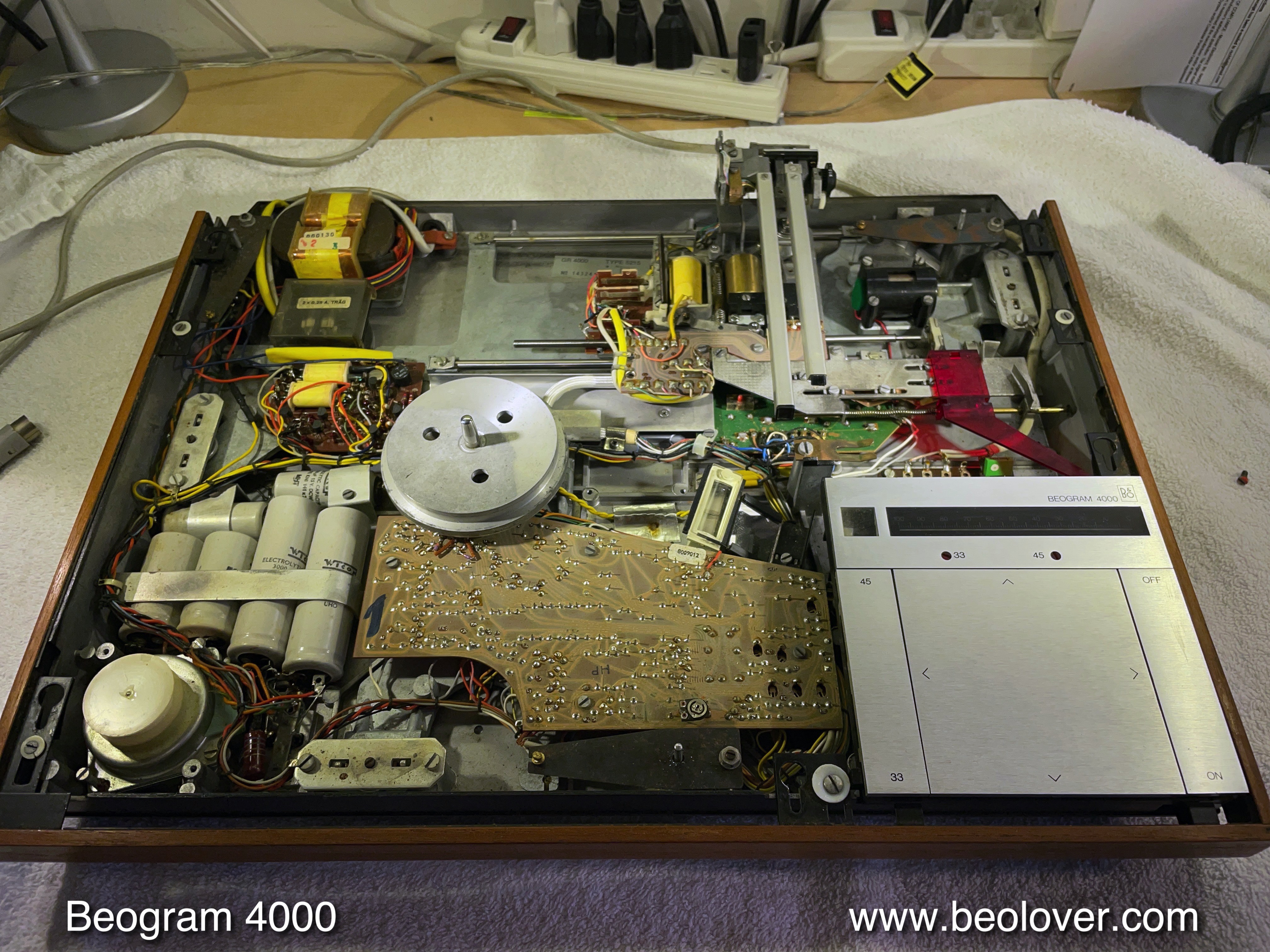
This shows the unit as received with the aluminum panels off:
As usual I started out with restoring the carriage. The first step was to extract the components of the arm lowering and carriage transport systems. This shows the arm lowering system:
I removed all the moving parts and also the rods and spindle of the carriage transport:
I cleaned everything in an ultrasonic bath:
Beolovely! While the carriage is 'liberated' it is also the perfect time to tend to the solenoid activated switches. In this unit they were (as usual) bent out of shape and oxidized:
It is best to remove the small PCBs that hold the terminals and then extract the terminals for gold plating. This shows the underside of the carriage. The small PCBs at the bottom hold the switch carriers:
I unsoldered them:
and extracted the terminals:
While the carriage is up it is also convenient to tend to the switches on the carriage position detector PCB. It has five switches, one (green plunger) is the singles position detector which is a break switch. It is especially susceptible to malfunction since only slight oxidation already takes it out of commission (you will notice if the arm is lowered immediately after pressing ON):
I removed the terminals and the plunger assemblies (they are usually full of crusted lubricants). The plungers needed to be cleaned ultrasonically:
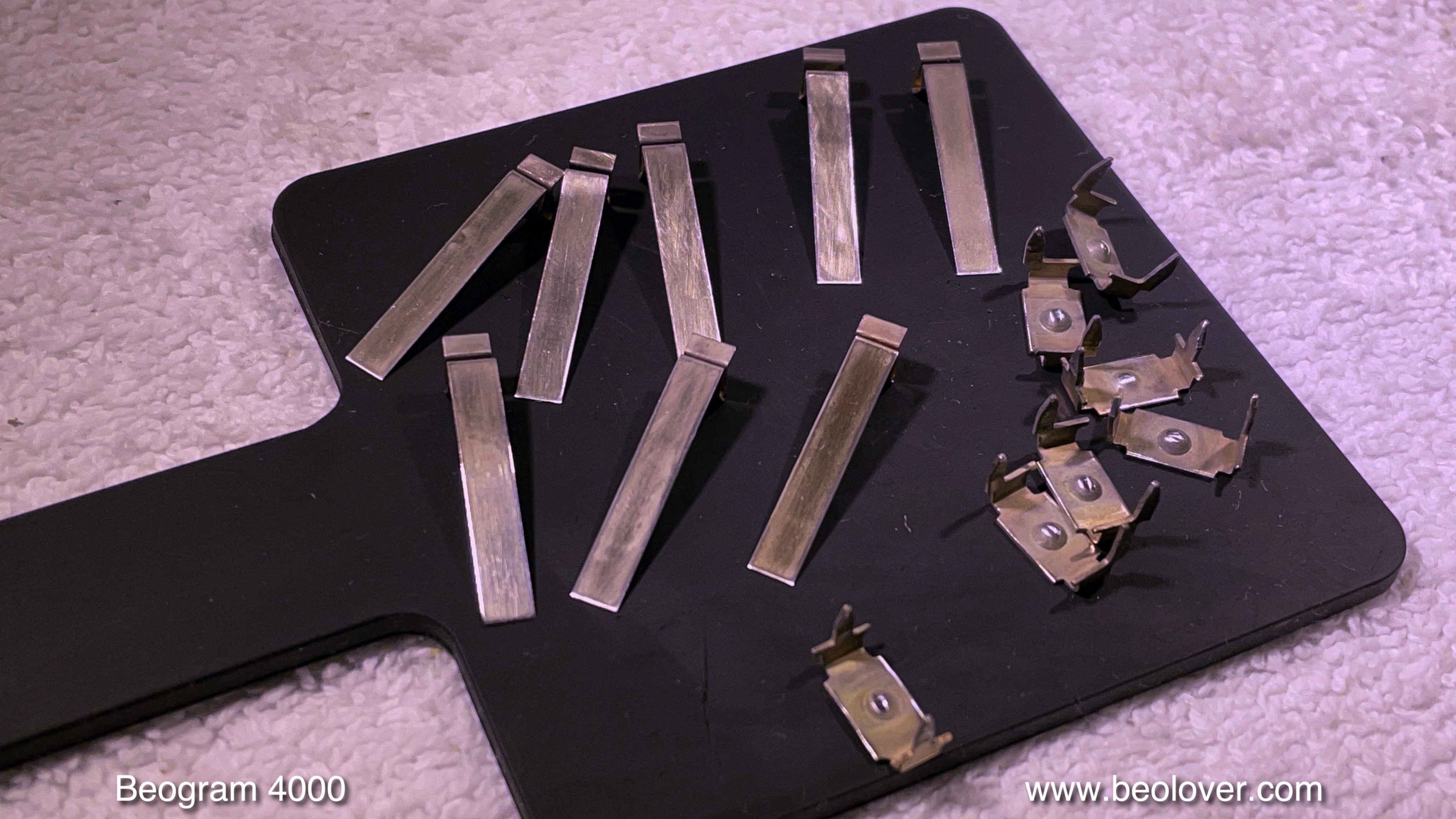
This shows the gold plated switch terminals of both solenoid and carriage switches. I coat them first with a Ni film for better adhesion and then with a Co-Au alloy, which is harder than just Au:
Then I re-installed the terminals:
On the carriage position board I also exchanged the solenoid current limiting resistor (red):
These resistors tend to fail since they see some pretty strong currents. I replace them with 2W instead of the 1W specified originals. This shows the rebuilt carriage PCB reinstalled:
Another item to address while the carriage is up is the repalcement of the solenoid transistor. They also have a tendency to fail after almost 50 years. It is bolted to the bottom of the enclosure for thermal management:
I replaced it with a new TIP41C:
Another item to replace on the carriage is the tracking sensor light source, which originally is an incandescent bulb:
This shows the original bulb housing in comparison with the Beolover LED based replacement. In this particular case the original bulb had already been replaced with a non-fitting generic bulb, which had to be 'embedded' into the plastic housing via heat and glue. Whoever did it also got rid of the trimmer that allows adjusting the bulb brightness. Messy.
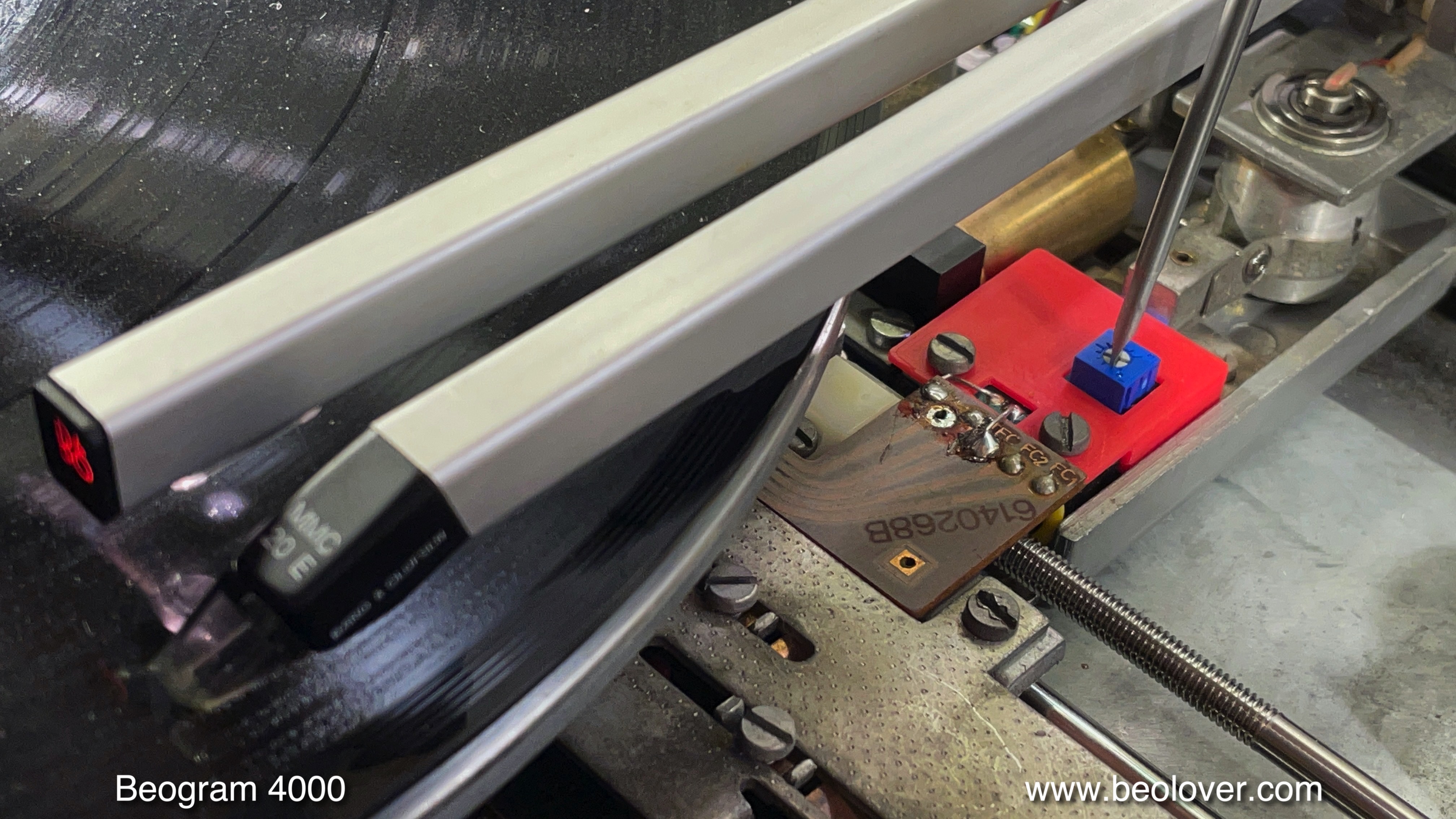
This shows the LED replacement in place. The blue box replaces the normally externally installed trimmer for tuning the brightness:
One of the biggest 'standard issues' of the 4000 is their brittle cartridge mount. Most of them have it, and it is a sad moment when it breaks off while removing a cartridge. Usually the plastic tab sticks deep inside the cartridge, and then it needs to be sent off for restoration. Therefore, I replace all of them as a standard item of my restoration packages with a 3D printed nylon based replacement.
I removed the arm from the carriage and had a closer look:
In this case the lower part of the plastic insert that carries the grounding tab was also cracked. I have replacement part for this case, too:
This shows both top and bottom part stuck into a cartridge:
Here you can see how the gold plated grounding tab inserts into the cartridge:
And here is everything together installed in the aluminum tube of the arm:
It is important to make sure that cartridges fit flush with the aluminum tube when installing the parts:
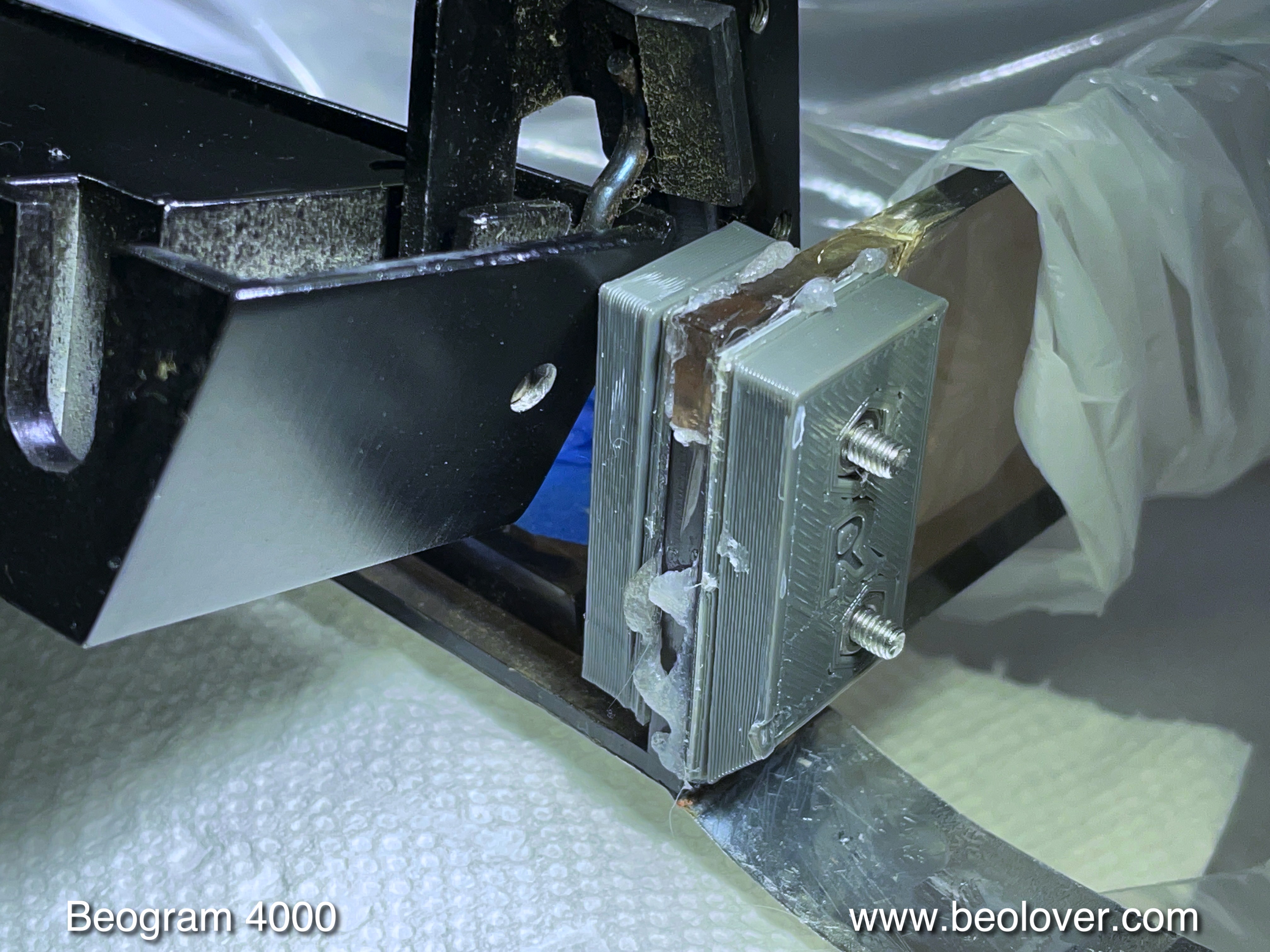
Basically, I use a defunct cartridge (from a sad ebay shipping disaster) to push the glue coated inserts into the tube until the cartridge is flush. Then I let the glue dry and remove the cartridge.
After all these steps I reinstalled the carriage and the arm lowering mechanism and turned my attention to the electronic control system:
First I removed the keypad cluster (if you do this at home, take a few pictures of how the wire harness is coiled under the cluster before you remove it - it can be difficult to get it back in if one does not remember how the fairly thick cable mess is supposed to coil up.
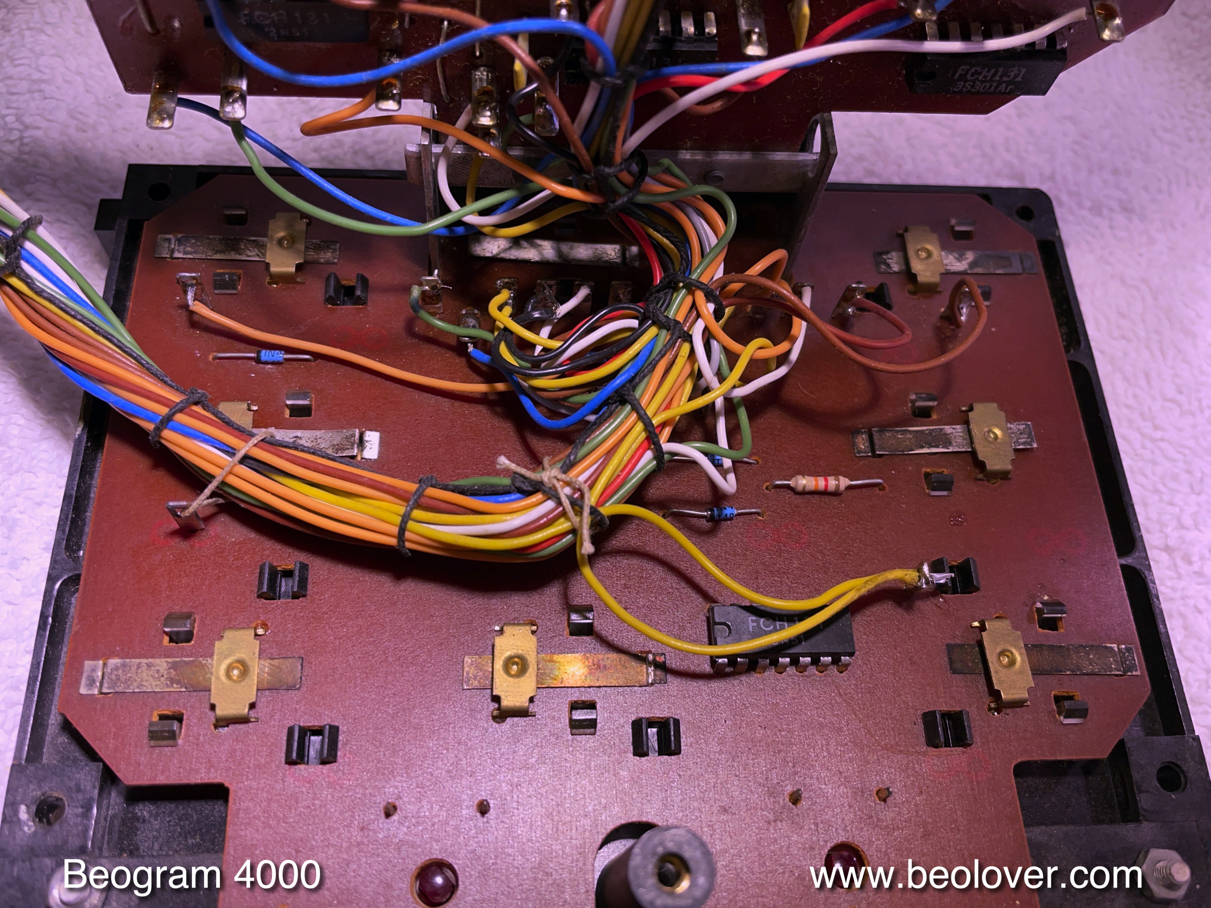
Once the keypad is out, one can turn it around and put the PCB in service position. This reveals the light bulbs and the switch terminals:
The terminals are usually also very corroded and need to be gold plated, like the other ones shown earlier:
I removed them:
and also Ni/gold plated them:
Then I reinstalled them:
This looks much nicer! Then I replaced the light bulbs with LEDs. This shows the Beolover LED boards that replace the scale illumination bulbs:
This is how they install:
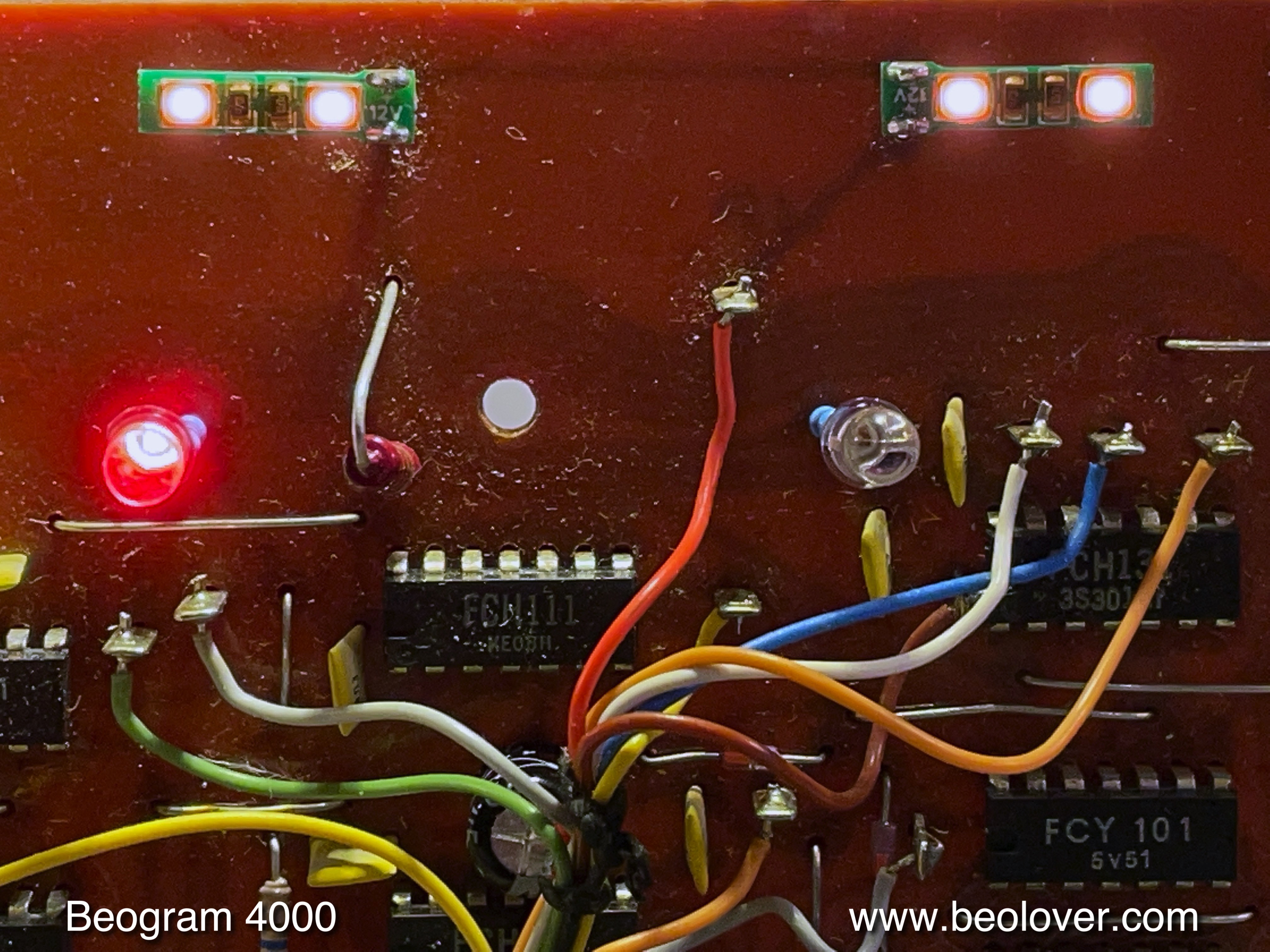
The other two bulbs illuminate the RPM trimmers from the back, doubling their purpose as RPM indicators. They can be replaced with standard red LEDs and current limiting resistors. This shows everything in action (at 33 RPM):
After rebuilding the keypad, it was time to tackle the reservoir and motor capacitor bank and the AC platter motor. This shows the original setup:
As so often the main capacitors showed signs of leakage:
This usually leaves behind a mess in the capacitor compartments in the enclosure:
This can be cleaned by soaking in ethanol for a while and then wiping it off:
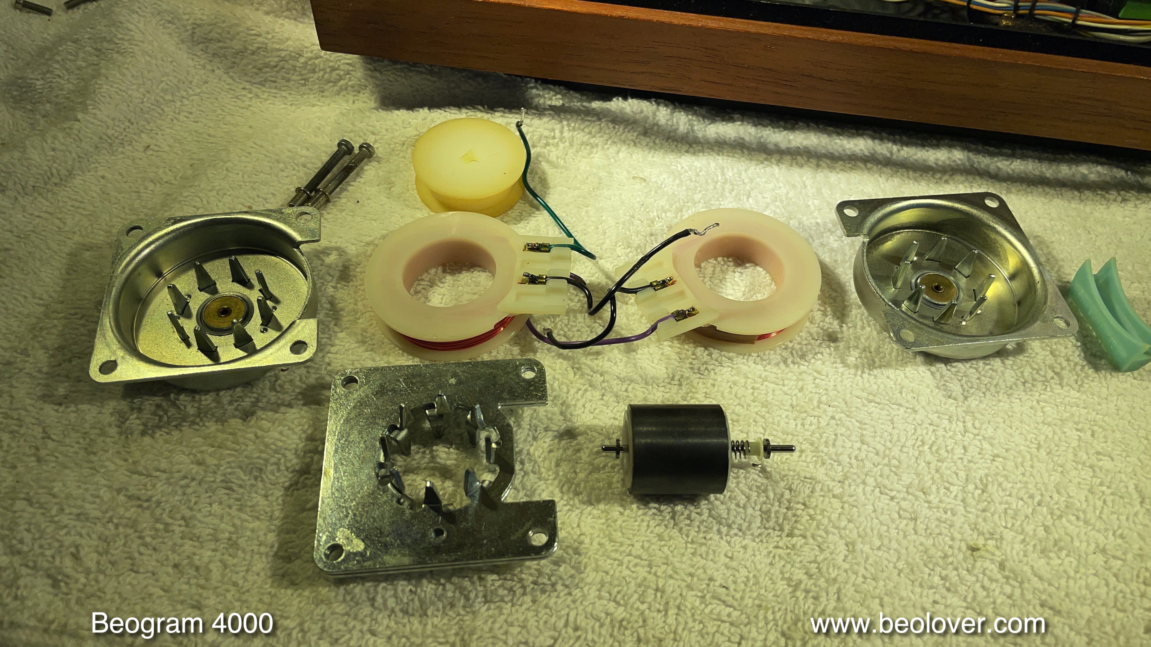
After removing the capacitors I took the AC motor apart
and inserted the enclosure into motor oil. The enclosure contains the sleeve bearings that I am oil infusing with this procedure under vacuum:
After 24 hrs I extracted the motor parts and cleaned off excess oil. Then I put the motor back together and also installed the new capacitors:
Then I focused on the PCBs. I removed the main PCB. This revealed the two transistors of the push-pull stage that drives the AC motor:
These transistors are also prone to fail, and so I replace them as part of a restoration:
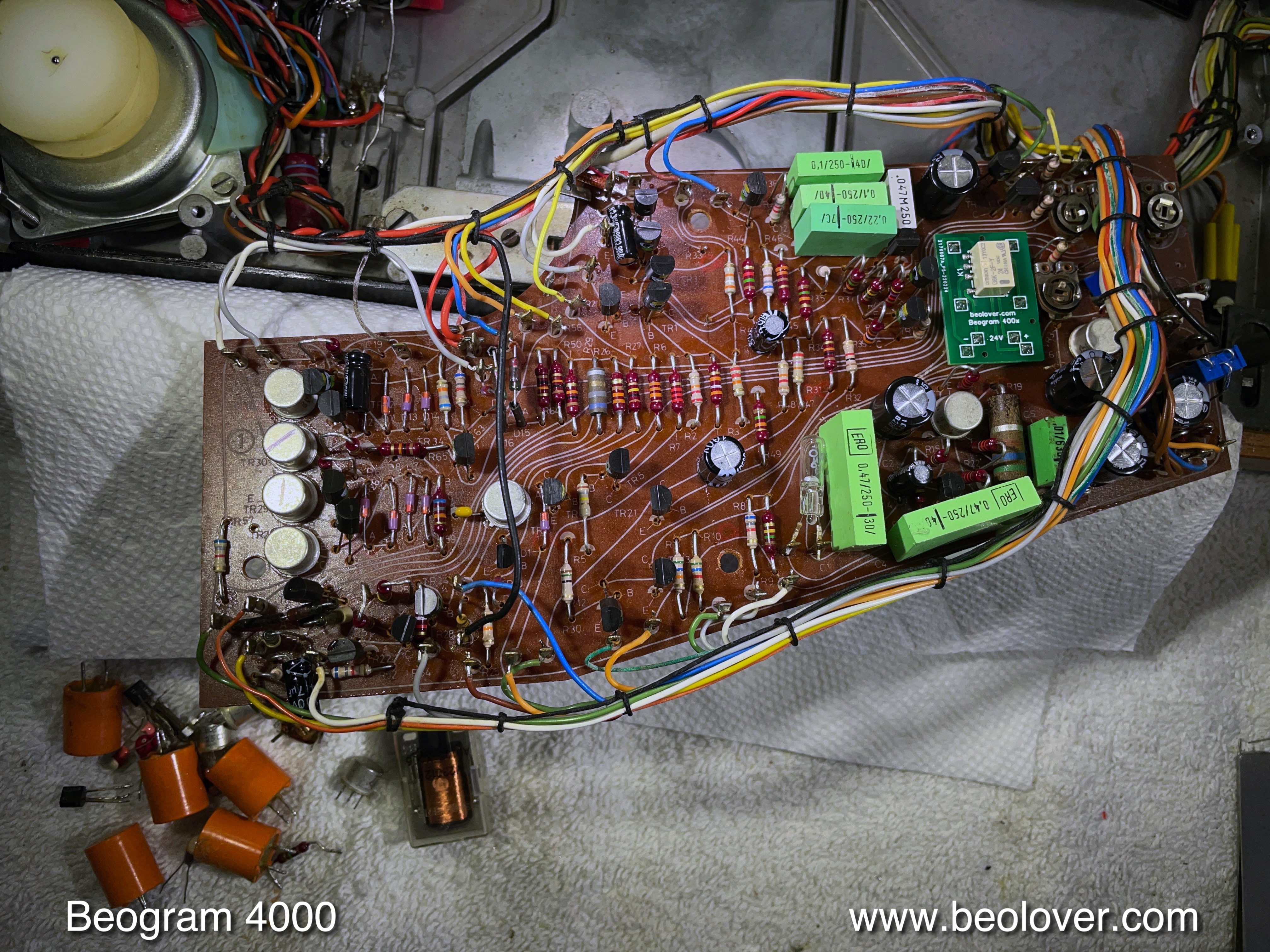
On the PCB I replace the electrolytic capacitors, the H-bridge transistors, the transistors that drive the solenoid main transistor, the transistor that amplifies the record detector signal and the RPM relay and RPM trimmers. This shows the PCB in its original condition:
And with the components replaced:
On the power supply PCB there are only two electrolytic capacitors, which I also replaced:
I usually also replace the light bulb in the sensor arm with a LED assembly:
In this particular Beogram I also had to tend to the photocell in the sensor arm compartment. Someone had tampered with this before and the cell was in a wrong location, i.e. was not able to detect the light reflected by the platter. This disabled the arm sensor. See separate post linked above for more details. This shows the cell back in its proper place:
Which restored the sensor signal to a perfect >3V amplitude:
This Beogram 4000 came with a damaged fuse cover that lost the tab for securing it with a bolt. This is important, since the fuses are at grid voltage, which makes this a safety hazard.
As usual, the fuses had loose contact cups
So I replaced them with new ones:
I designed a 3D printable cover for the fuse box, which I installed to secure the fuses:
Like pretty much all Beogram 4000s this one also had cracked plinth guidance washers. Their exchange requires removing all the bolts that hold the plinth in place. The perfect moment for removing the plinth and re-gluing the loose corner on the right side:
Then I installed the new guidance washers:
This shows one of them in place:
Then I did all the mechanical and electronic adjustments. First I adjusted the floating chassis and the arms height and parallelism. Then came the tracking weight
And arm lowering limit. After taking are of the arm, I adjusted the tracking feedback:
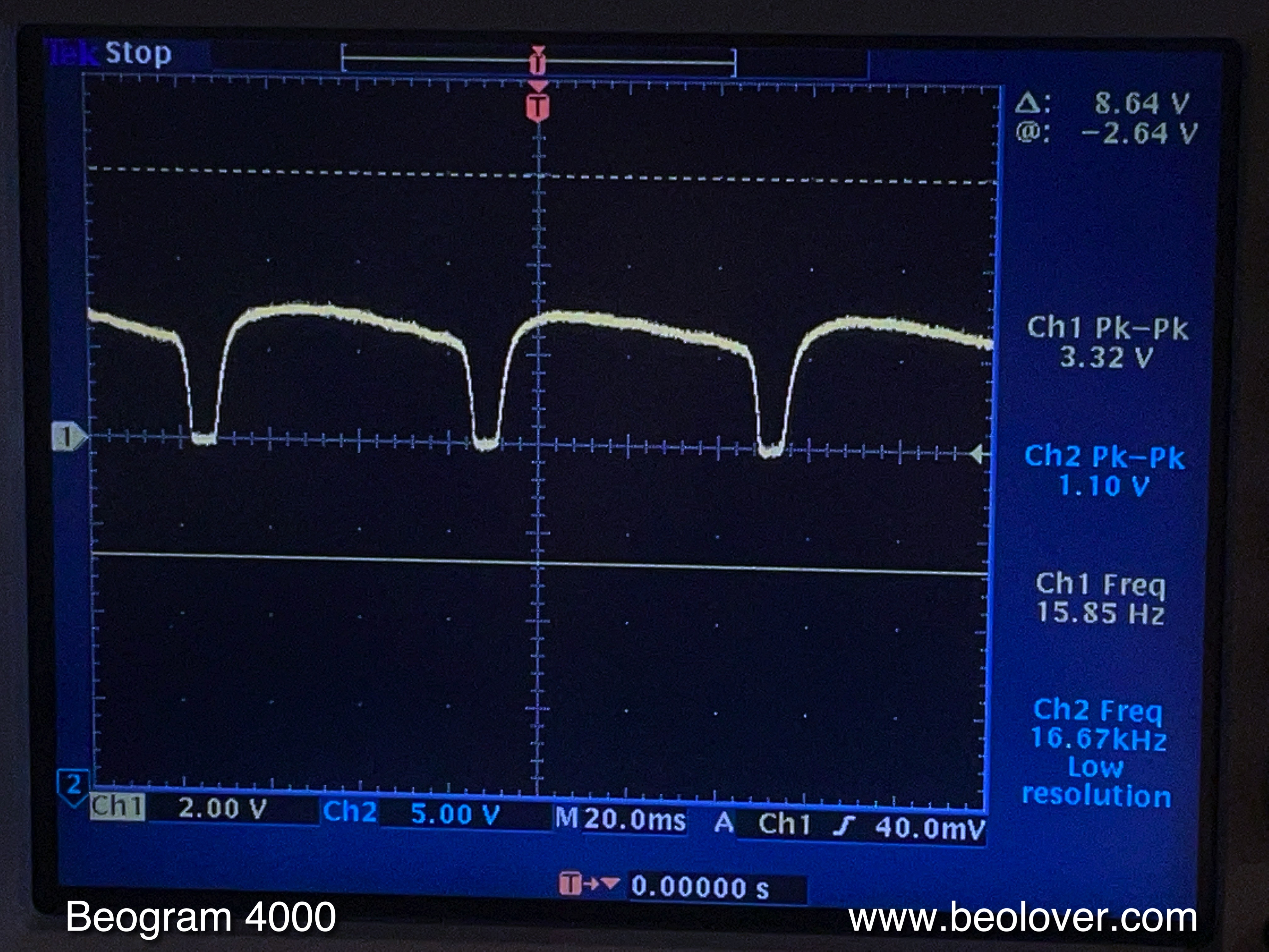
After this it was finally time to give this Beogram its first spin. But no cigar! The AC platter motor spun only erratically. I measured the motor voltage, and received this almost square wave signal. Normally this should look like a decent sine wave!:
It turned out that this unit had a bad automatic gain control bulb in the Wien-bridge oscillator that drives the AC motor synchronously. After some study and experimentation I was able to replace the bulb with a precision 100 Ohm trimmer and six 1N4004 diodes for gain control. These parts had to be installed on the solder side of the PCB:
This restored a decent motor wave:
Read more detail about this process in the post that was mentioned at the beginning of this report.
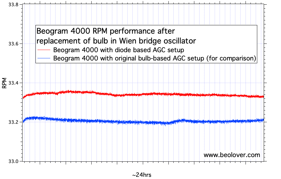
Now it was time to do a RPM stability test to verify that the repair had not introduced unwanted instabilities in the oscillator. I did this with the BeoloverRPM device that allows logging the RPM in 10s intervals over extended periods of time:
The curve that I measured is shown in red in this graph:
The blue one is from another Beogram 4000 that still has the original bulb. It seems that the diodes perform as well as the bulb, and that the RPM has a similar stability.
After this I finally focused on the signal path. This shows the original corroded DIN5 plug:
I first installed a new plug and then played the deck, but one channel was missing. It turned out that the cable had a bad lead. So I replaced it with a DIN5 cable from
SoundsHeavenly where I removed one of the plugs for installing it inside the Beogram. This shows the nice gold plated plug terminals of this cable:
And here you can see the other end of the cable as installed in the Beogram:
I usually install a switch (red) that allows connecting signal and system grounds in case there are hum issues. This is especially helpful if the deck is used on a RCA input receiver.
And now it was finally time to enjoy this restored Beogram! I put on a recently acquired CTI record by George Benson, his 1976 live album "In concert - Carnegie Hall" (
CTI 6072 S1). Of course this album had been ultrasonically cleaned on a
CleanerVinyl ProXL setup using a multi-frequency cleaning protocol enabled by a
UC-3360 three-frequency cleaner. This restored the album to a like new quality. I really started liking this album. Especially 'Take Five' and 'Summertime' are great tracks. It also has great recording quality, especially for a live recording. CTI was an awesome label!
This shows the Beogram playing this nice album. A perfect combination!:
Beolovely! Let's see if I can fix the cracked hinge of the plexiglass hood this Beogram came with!..;-). Stay tuned!