Featured Post

Beolover SyncDrive: DC Platter Motor Replacement for Beogram 4002 and 4004 (Type 551x and 552x)

Late Beogram 4002 and the 4004 (Types 551x and 552x), which have DC platter motors instead of the earlier synchronous AC motors usually suff...

Showing posts with label recapping. Show all posts

Sunday, July 13, 2025

Michigan Beogram 8002 Electronic Restoration

The electronic restoration process for the Beogram 8002 mainly involves the two circuit boards, PCB 1 - PCB 2, the Beogram transformer module and the control button panel.

Here are PCB 1 and PCB 2.


Starting with PCB 1, here is a survey of the capacitors that will be replaced.


Pretty straight forward but I always like to pull the base off the old C27 capacitor (2200uF, 40V) and re-use it on my replacement capacitor.  The three-pronged base of the capacitor provides good support on the circuit board and is the negative terminal of the capacitor...so it is very handy to re-use on my replacement cap.


Here is a survey of the PCB 1 capacitors after I replaced them.  I like to replace all of the electrolytic capacitors 4.7uF and smaller with WIMA MKS, non-polarized capacitors (the red ones in the photo).


Next is the PCB 2 assembly.  It houses the microcomputer IC (a 40-pin device).  There is just one electrolytic capacitor on this board and it is for the +5 VDC power required for the uC device.  In this case, the capacitor is blown as seen in the photo below.


On the restoration for this board I remove the uC device first so I can replace the 40-pin socket with a newer one.  While the C1 capacitor is better exposed I replace it.


Now the Beogram 8002 uC device is re-installed.

REMINDER: Always take electrostatic protection precautions when handling sensitive electronic components such as digital integrated circuit devices.

Also, re-inserting a 40-pin device into a socket is not as easy as you might think.
The pins will never line up perfectly and care must be taken not to accidentally bend a pin while getting them all in place.


There is a lone control wire for the uC reset signal from PCB 2 that attaches to a terminal post on PCB 1.
The wire is a small gauge, shielded wire that often breaks where it solders onto the connector for the terminal post.  

That was the case on this Beogram 8002 so I added some extra support when I re-installed the wire.


PCB 1 and PCB 2 are now complete.  I will wait to re-attach the PCB 2 top lid until I do some Beogram 8002 functional testing. 


The electrolytic capacitor inside the Beogram 8002 transformer assembly is a non-polar capacitor that the Beogram requires for the platter motor to turn.  It is the starting phase capacitor and since it didn't fit on PCB 1, the engineers located it in the transformer compartment.

The value of the phase capacitor is different for different line frequencies.  In the US, where the line voltage is at 60 Hz, the Beogram 8002 phase capacitor is 27uF.


The Beogram 8002 Control Panel doesn't have any capacitors to replace but I do like to take it apart for cleaning, checking and installing a little test connector.

This Control Panel is in very nice condition.

The black plastic tabs in the photo that attached the PCB to the Control Panel frame are often broken (Who knows why).

These are all accounted for.

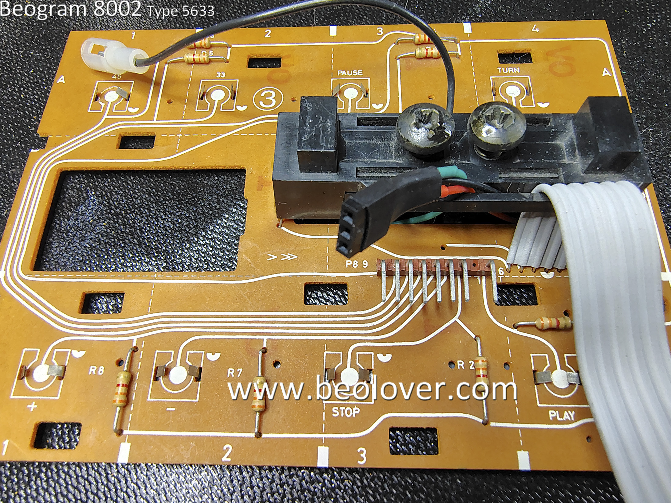
The highlighted module in the photo is where a single lamp and two LDR devices live.
The two large screws adjust the amount of light that passes from the lamp to each LDR.
This mechanism sets the idle voltage control for the Beogram 8002 servo motor that moves the tangential arm assembly.  The B&O service manual says to set the screws so the Forward and Reverse scanning functions are at an idle voltage level of 620mV.

These voltages feed into the positive input of the Op-amps controlling the tangential arm servo motor.
The 620mV level is the input level for the Forward and Reverse controls where they are not driving the motor forward or reverse.

When someone is pressing down on the Forward or Reverse scanning buttons a spring loaded aperture allows more light to the LDR and sends a higher voltage to the servo motor control to move the arm assembly forward (or backwards).

The adjustment of these scanning function screws is always a pain for me.
To set the 620mV level the LDR is measured to ground.
There are no convenient test points provided on the control panel and there have been times when I have wanted to check the LDR levels without completely opening up the Beogram.

For that reason I always install a little test connector that is accessible by pulling off the Control Panel.
That way the measurement and adjustment can be made at any time later.

Here are some photos to demonstrate....


The underneath side of the Control Panel is much cleaner than other Beogram 8002 units I have worked on. Very nice.


Here are my three test wires for measuring the two LDR devices.


...and here is the test connector installed and ready to use.


Everything is now complete where I can do a quick test to see if the Beogram 8002 comes to life.

I assembled all of the components on my bench with the floating chassis and plugged the Beogram 8002 in to AC power.


Happily I got the red dot on the display indicating "standby" and I observed the little wiggle of the platter as power is applied to the system.
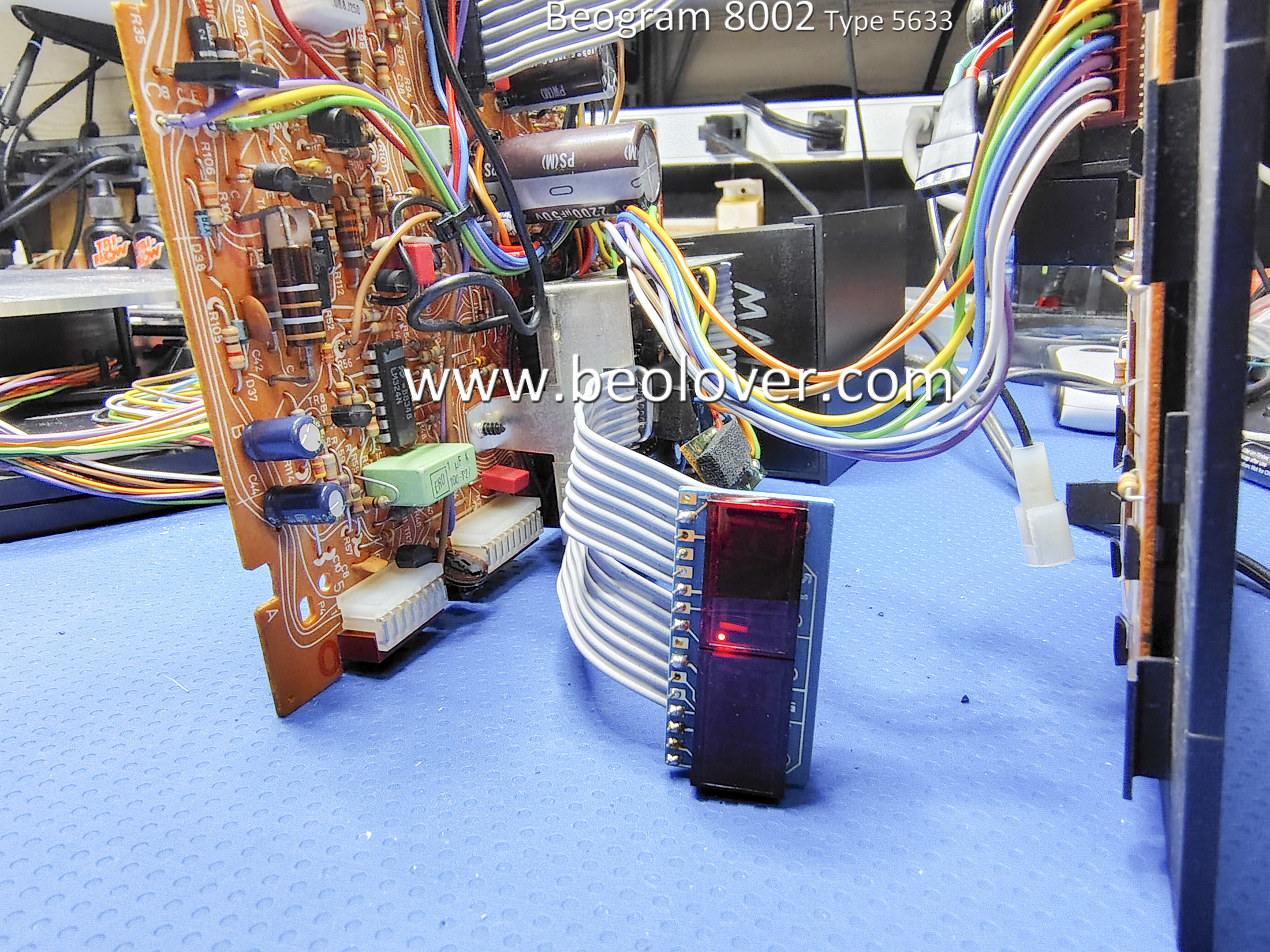


The platter turn functions worked with both 33.33 and 45 RPM speeds able to lock in as expected.

I pressed Play and the Beogram arm assembly moved forward...Then it stopped moving.

That isn't totally unexpected during a "first power on" test.  It usually means there is a problem with the scanning LDR assembly in the Control Panel that I mentioned earlier.

Time to connect up my handy test connector and measure the LDRs.


Sure enough, the voltages for the scanning LDR devices were well over 1 V.  Too high over the 620mV level they should be at.  Of course this messes with the Beogram servo control circuit and the arm tends to stop.

I was able to adjust the LDR voltages to a level where the Beogram would operate but it was with the LDR voltage steady-state values of around 800mV.  However, that was with the adjustment screws fully opened up.

That isn't a good long term solution so I will have to return to the Control Panel assembly and do some work on the LDR devices. 

I want the LDR voltage levels to be around the 620mV idle voltage level with plenty of room for adjustment of the adjusting screws.

Sunday, October 22, 2023

Beomaster 5500 Type 2333: Reassembly and Initial Testing

The previous project post showed the dis-assembly of the Beomaster 5500 for doing work on the circuit boards.

That post left off with the output amplifier heatsinks needing to be re-installed on the Power Supply & Output Amplifier board.

I used Sil-Pad thermal insulators in place of thermal paste as it is easier to work with (less messy) and does a great job.  There are two lone transistors (IC205 and IC405) that fit between the heatsink channels that do require some thermal paste compound as they don't have spring clips to press them against the heatsink (like the other, larger transistors do).


The next set of pictures show the re-assembly of the restored boards back into the Beomaster 5500 cabinet.


With the circuit boards re-installed I was able to plug the Beomaster 5500 into AC power and do some initial tests on the Beomaster.

I did some quick measurements of key DC voltages with the Beomaster turned on.
The positive and negative 40 volt rail voltages were there as well as 5 volts, 8 volts, 12 volts, 13 volts and 28 volts.

I adjusted the Left and Right channel no-load current biasing for the Output Amplifiers and then tried playing some music with the Beomaster.

Here are photos of my measurement probes for the the no-load current adjustments.
That adjustment requires the Beomaster 5500 to be on (out of Standby), have the volume level of the amplifier set to zero and no speakers connected to the amplifier.


The trimmers were adjusted so the voltage reading across the emitter resistors of the channel measured 11 millivolts DC.

The Beomaster 5500 was now ready for a quick listening test.
When the voltages check out and the no-load (idle) current has been adjusted, I like to do a listening check of the amplifier.  It is like an early reward for the restoration work to get to this point.

I connected up two sets of Beovox speakers in the workshop.  A pair of MC120.2 speakers and a pair of S-55 speakers.  For a music audio source I connected an iPod to the Beomaster 5500 CD source input.


The Beomaster 5500 sounds great (as expected).
Now I can complete the rest of the Beomaster 5500 reassembly and move on to some audio tests.
I will also be doing some functional testing of this Beomaster 5500 with other Beosystem 5500 components and the MCP remote control.

Wednesday, October 11, 2023

Beomaster 5500 Type 2333: PCB Restoration Tasks

In the previous post I assessed the restoration tasks of this Beomaster 5500.

This post shows the work performed on the Beomaster 5500 circuit boards.

The first step was to remove the boards that will need to be worked on.
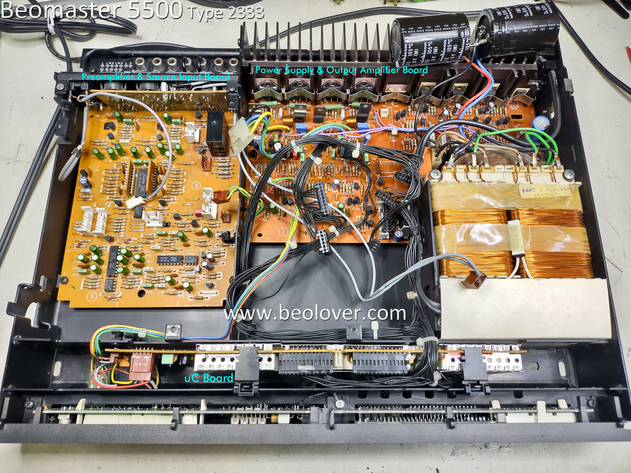
Here is a photo of the Beomaster 5500 prior to removing the boards.  The boards that will be worked on are labeled in the photo.


The following pictures are a sequence of Beomaster 5500 photos showing the boards being removed.


The last photo above shows the Microcomputer board removed...so I will start with that one.
Here are the before and after pictures of the Microcomputer board restoration.
There are just two electrolytic capacitors in this board.
There is also a CR2430, 3V Lithium battery.  It still measured 3V but it is still good to go ahead and replace the battery with a brand new one.


Note that for installing the new CR2430 battery I installed a battery holder for it.


The next board assembly is the Cooling Fan assembly.  It also has two electrolytic capacitors that I replaced.


The FM board came next.

Here is the FM board as it was received.


Here is the FM board after the electrolytic capacitors were replaced.


Here is the recapped Preamplifier board.  I didn't take a stand-alone before recapping photo of it so here are a couple of after recapping photos.  I replaced all of the signal path electrolytic capacitors with non-polarized, Nichicon audio capacitors.

Note that the highlighted Muting Relay had already been replaced so I didn't change that component.


The last Beomaster 5500 circuit board I worked on is the Power Supply and Output Amplifier board.
Here it is removed from the cabinet prior to any restoration work.


The white thermal compound on the heatsink assembly is just getting to the point where it feels a little bit dry.  For that reason I decided to remove the heatsink, clean the old thermal paste off and put new thermal protection on during re-assembly.

Here are photos of the heatsink removal and thermal paste cleanup.


Here is the Power Supply and Output Amplifier after I replaced the electrolytic capacitors, power supply relay and trimmer resistors for the output transistor bias.
There are two signal path blocking capacitors (2.2uF) for the audio signal from the Preamplifier board to this board.  I replaced those two capacitors with the same type I used in the signal path on the Preamplifier board.


Here is a closer photo of the new trimmer resistors.


The original power supply relay looked like this, de-soldered from the board.


The relay (RL1) still works but judging by the heat marks on the board and the fact that the Muting Relay (same type of relay) was already replaced...it is a good idea to go ahead and replace this relay.

I used a modern, enclosed relay.  It has two extra relay contacts that I had to cut off so that I end up with an identical mounting foot print.  I have used this replacement relay before on my own Beomaster 5500 and Beomaster 5000 amplifiers so I know it works well.


The next steps are to re-install the output amplifier board heatsink assembly then re-install the boards back into the Beomaster 5500 cabinet.

Friday, August 11, 2023

Beomaster 1900 Type 2904: Post Recapping Power On Test

Power can now be applied to this Beomaster 1900 unit.

Standby mode works


...and the On mode (when a source is selected) works


Here is how I arrived at this point since the last post.

I performed one key service manual voltage adjustment, 15-Volt Supply.


I performed the capacitor replacements on the Control Panel PCB.
Here are the before photos of the Control Panel recapping.


In addition to the capacitor replacement I opened the three slider controls (Bass, Treble and Balance) to inspect and clean them.

The Balance control was in great shape so it only required cleaning.


The Treble control had a broken plastic slider bridge.  It is the typical problem where the plastic piece holding the contacts in place gave way.


This is very common and the Beoparts Store carries a replacement slider bridge for this problem.


Continuing on, the Bass slide control was in great shape like the Balance slider was...so it only required cleaning.


Here is the Control Panel PCB recapped and ready for use again.


After the Control Panel tasks were done I replaced the lamps in the lamp modules.

I replaced the incandescent lamps with new incandescent lamps from Beoparts on the Volume indicator and Source Select boards as the lamps themselves make up the functionality of their respective circuits.


On the lamp panel for illuminating the slide control indicator masks, I like to change to LED lamps.
The reason for that is because the LEDs produce less heat under the plastic lenses and indicator masks.
These lamps are always on when the Beomaster is not in Standby mode and are powered by the 15 V power supply. They aren't part of any audio circuit functionality like the other lamps in the Beomaster are.


In the next post I will do some more voltage checks and will adjust the No-Signal (idle) current of the output amplifier along with a few other service manual checks. I will also connect up some Beovox speakers and see how this amplifier sounds.