Featured Post

Beolover SyncDrive: DC Platter Motor Replacement for Beogram 4002 and 4004 (Type 551x and 552x)

Late Beogram 4002 and the 4004 (Types 551x and 552x), which have DC platter motors instead of the earlier synchronous AC motors usually suff...

Showing posts with label power on test. Show all posts

Friday, August 11, 2023

Beomaster 1900 Type 2904: Post Recapping Power On Test

Power can now be applied to this Beomaster 1900 unit.

Standby mode works


...and the On mode (when a source is selected) works


Here is how I arrived at this point since the last post.

I performed one key service manual voltage adjustment, 15-Volt Supply.


I performed the capacitor replacements on the Control Panel PCB.
Here are the before photos of the Control Panel recapping.


In addition to the capacitor replacement I opened the three slider controls (Bass, Treble and Balance) to inspect and clean them.

The Balance control was in great shape so it only required cleaning.


The Treble control had a broken plastic slider bridge.  It is the typical problem where the plastic piece holding the contacts in place gave way.


This is very common and the Beoparts Store carries a replacement slider bridge for this problem.


Continuing on, the Bass slide control was in great shape like the Balance slider was...so it only required cleaning.


Here is the Control Panel PCB recapped and ready for use again.


After the Control Panel tasks were done I replaced the lamps in the lamp modules.

I replaced the incandescent lamps with new incandescent lamps from Beoparts on the Volume indicator and Source Select boards as the lamps themselves make up the functionality of their respective circuits.


On the lamp panel for illuminating the slide control indicator masks, I like to change to LED lamps.
The reason for that is because the LEDs produce less heat under the plastic lenses and indicator masks.
These lamps are always on when the Beomaster is not in Standby mode and are powered by the 15 V power supply. They aren't part of any audio circuit functionality like the other lamps in the Beomaster are.


In the next post I will do some more voltage checks and will adjust the No-Signal (idle) current of the output amplifier along with a few other service manual checks. I will also connect up some Beovox speakers and see how this amplifier sounds.

Thursday, April 28, 2022

Beomaster 4400 Type 2419: Reassembly and Power On Test

The hard work restoring this Beomaster 4400 unit is starting to pay off.
I reached the milestone of reassembling the Beomaster and testing its power supplies.

In the last post the Beomaster 4400 reassembly had begun but left off needing the output amplifier transistors to be mounted on the heatsinks. 

The transistors are now installed on the heatsinks with SIL pad thermal insulators.


I also wired up the power switch and mounted an arc suppression device like I usually do with these amplifiers.


The arc suppression device installation required tapping a couple of M3 holes in the Beomaster bracket that secures the large filter capacitors.

I started installing these devices after one Beomaster 4400 had arrived with severely charred switch contacts.  Because these power switches can no longer be sourced (other than stealing on from another Beomaster 4400) I think it is worth a little more effort to protect them.

Before plugging in and turning this Beomaster 4400 on for the first time I plugged it in to my Dim Bulb/Variac tester.

That tester allows me to slowly apply AC power to the Beomaster while monitoring how much current it is drawing.  The light bulb draws current away from the amplifier if too much is present.
Doing that protects the Beomaster from having more component damage if there is a short circuit somewhere.

Here is a good example of why it is good to start out with this type of testing.

This Beomaster started drawing too much current right away as I dialed up the AC voltage on the variac.
It reached about 400mA by the time I was at 50 V.


I stopped and removed power.

After going over the wiring of the Beomaster I found and fixed the problem.

Running the test again I now have a clean power up of the Beomaster unit.


Around 260 mA with full input power applied.
That matches what I get with other Beomaster 4400 units.


With the Beomaster 4400 able to power on safely I performed a number of power supply voltage checks.

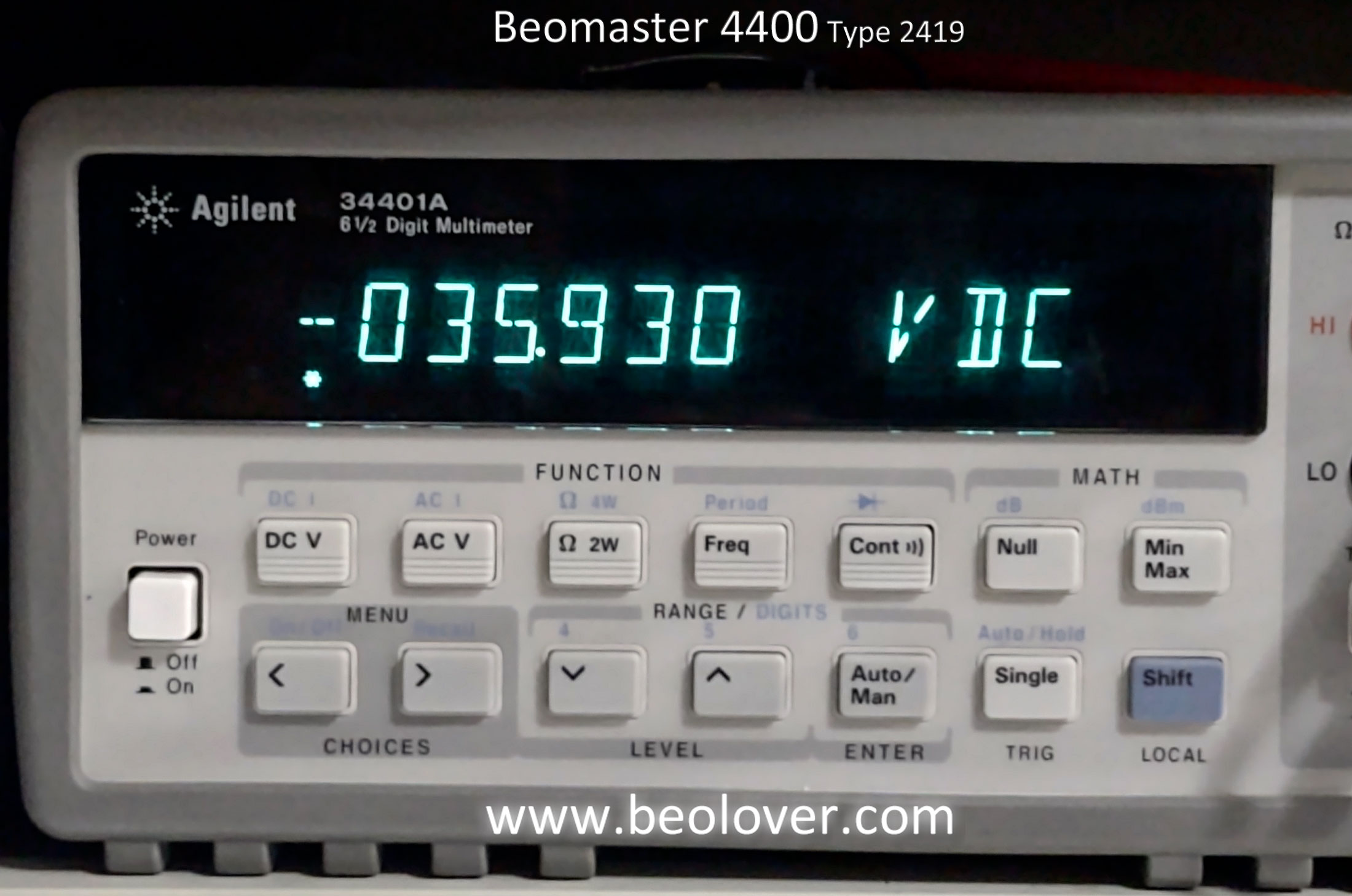
Here are the +15 V and +35 V reference voltages.


Next is the -12 V reference for the audio muting circuit.


Here is the reference voltage for the Phono, Tape 1 and Tape 2 preamplifier circuits.


Here are the 24 V Left and Right channel reference voltages for the preamplifier tone controls.


Here are the power amplifier positive and negative rail voltages.


Finally, here are the Left and Right channel no-load current checks and adjustments for the output amplifier.

The service manual says to measure across the emitter resistors and adjust for between 10 mA and 15 mA.

For now I will roughly set them above 10 mA.  I will adjustment them more precisely later.  Probably at 12 mA.


It feels great to finally have this Beomaster 4400 amplifier powering on again.

In the next post I will start in on some bench testing that is include some actual music listening tests.

Monday, April 13, 2020

Beomaster 4400 Type 2419 - Power on testing: Part 2

The Beomaster 4400 is finally reassembled for a second round of power on testing.  In the previous post I had to replace the power on/off switch because the original switch was badly burned.  The new switch is a rebuilt switch that I tested in the last post.

While planning the reassembly of this Beomaster I looked at various options for preventing deterioration of the power on/off switch contacts during switching. I know there is arcing going on when the mechanical switch makes the line connection to the Beomaster power transformer. The original switch was totally burned up and the replacement switch also showed signs of arcing on its contacts. I cleaned and smoothed the contacts the best I could and I don't want another one of these switches to burn up.

A number of audio manufacturers used RC snubber devices and small safety capacitors across switch contacts to reduce the arcing when the switch is operated. In my investigation of those devices I am not convinced they are as effective as I would like them to be.  I finally found a device specifically for arc suppression across contacts. It is called the NOsparc GGXAC1F480.  It is designed for use in protecting the contacts of relays on HVAC units so I can see where someone would think it is overkill for this power on/off switch case ;-).  Never the less I was impressed by the Arc Suppression Technologies video that showed how effective their arc suppression device is. I called the company up and spoke with one of their engineers to find out if their product would work in my Beomaster 4400 on/off switch application. He confirmed that it would work so that is the route I took.

The NOSparc device is pretty good sized as seen in the photos below. I found a good mounting spot on the bracket that holds the reservoir capacitors then tapped a couple of M3 holes in the bracket and mounted the NOSparc device right there.


Here is the NOSparc device connected to the Beomaster 4400 power switch. I attached small connection terminals to all of the wires that connect to the switch. I also used a larger gauge jumper wire between the switch contacts from what was there originally.


I reapplied line voltage to the Beomaster in steps like I did the first time...a variac to slowly increase line voltage while monitoring current and a dim bulb tester.

No issues applying the power that way so I removed the dim bulb tester from the circuit and just connect the Beomaster directly to a line outlet.

The Beomaster turns on and I was able to check voltages.
Here are the rail measurements again.


I also checked the 24V input to Beomaster 4400 +15V regulator.  The voltage is good and the measurement stays at 24V this time.


Confident in the results so far I adjusted the no-load current for the output amplifiers to 14mV across the emitter resistors (on both the left and right channel).

After that I connected an iPod Nano to the Beomaster 4400 Tape 1 source input and listed to it via headphones. Finally...good sound is emitting from this receiver again.


Now for a bit of bad news :-(.  While I was testing voltages on the Beomaster 4400 the power switch started to act up again and would not always switch on.  It has no problem switching off but the power on function is proving to be unreliable. I can tell this is a mechanical problem so I see myself replacing this Beomaster 4400 power switch at least one more time.

I can continue to get this receiver to come on so I will be able to continue testing the Beomaster 4400 performance. Now to start looking for another power switch.