Featured Post

Beolover SyncDrive: DC Platter Motor Replacement for Beogram 4002 and 4004 (Type 551x and 552x)

Late Beogram 4002 and the 4004 (Types 551x and 552x), which have DC platter motors instead of the earlier synchronous AC motors usually suff...

Showing posts with label variac. Show all posts

Monday, April 13, 2020

Beomaster 4400 Type 2419 - Power on testing: Part 2

The Beomaster 4400 is finally reassembled for a second round of power on testing.  In the previous post I had to replace the power on/off switch because the original switch was badly burned.  The new switch is a rebuilt switch that I tested in the last post.

While planning the reassembly of this Beomaster I looked at various options for preventing deterioration of the power on/off switch contacts during switching. I know there is arcing going on when the mechanical switch makes the line connection to the Beomaster power transformer. The original switch was totally burned up and the replacement switch also showed signs of arcing on its contacts. I cleaned and smoothed the contacts the best I could and I don't want another one of these switches to burn up.

A number of audio manufacturers used RC snubber devices and small safety capacitors across switch contacts to reduce the arcing when the switch is operated. In my investigation of those devices I am not convinced they are as effective as I would like them to be.  I finally found a device specifically for arc suppression across contacts. It is called the NOsparc GGXAC1F480.  It is designed for use in protecting the contacts of relays on HVAC units so I can see where someone would think it is overkill for this power on/off switch case ;-).  Never the less I was impressed by the Arc Suppression Technologies video that showed how effective their arc suppression device is. I called the company up and spoke with one of their engineers to find out if their product would work in my Beomaster 4400 on/off switch application. He confirmed that it would work so that is the route I took.

The NOSparc device is pretty good sized as seen in the photos below. I found a good mounting spot on the bracket that holds the reservoir capacitors then tapped a couple of M3 holes in the bracket and mounted the NOSparc device right there.


Here is the NOSparc device connected to the Beomaster 4400 power switch. I attached small connection terminals to all of the wires that connect to the switch. I also used a larger gauge jumper wire between the switch contacts from what was there originally.


I reapplied line voltage to the Beomaster in steps like I did the first time...a variac to slowly increase line voltage while monitoring current and a dim bulb tester.

No issues applying the power that way so I removed the dim bulb tester from the circuit and just connect the Beomaster directly to a line outlet.

The Beomaster turns on and I was able to check voltages.
Here are the rail measurements again.


I also checked the 24V input to Beomaster 4400 +15V regulator.  The voltage is good and the measurement stays at 24V this time.


Confident in the results so far I adjusted the no-load current for the output amplifiers to 14mV across the emitter resistors (on both the left and right channel).

After that I connected an iPod Nano to the Beomaster 4400 Tape 1 source input and listed to it via headphones. Finally...good sound is emitting from this receiver again.


Now for a bit of bad news :-(.  While I was testing voltages on the Beomaster 4400 the power switch started to act up again and would not always switch on.  It has no problem switching off but the power on function is proving to be unreliable. I can tell this is a mechanical problem so I see myself replacing this Beomaster 4400 power switch at least one more time.

I can continue to get this receiver to come on so I will be able to continue testing the Beomaster 4400 performance. Now to start looking for another power switch.

Sunday, March 29, 2020

Beomaster 4400 Type 2419: Investigating the Power On Problem

I left off this Beomaster 4400 restoration thread having reassembled the receiver for a power on test.
That did not go as I planned and it appeared there was a problem with the right channel output amplifier circuit.

I disassembled the Beomaster 4400 partially so I could de-solder the leads to the output amplifier transistors that mount on the heatsinks.  I found two bad right channel TIP 146 Darlington transistors. That being the case I ended up checking all of the output amplifier transistors for both the left and right channels.

For reference, here are the locations and transistor types.


After replacing the two bad TIP 146 Darlingtons I was ready to try the power on test again.
The dim bulb remained off, so a good sign there, and I reached the line voltage level of 125 VAC, 60 Hz on the variac.

The +15 VDC power supply measured good as did the ±35 VDC rail voltages. Before I could continue with the other power supply measurements I noticed my voltmeters were starting to show the rail voltages going down.  They were decreasing slowly (increments of about 50mV) but they were dropping. The ammeter on the variac wasn't showing much of a current draw but something was wrong...so off with the power again and abandonment of another power on attempt.

During the power on test I noticed that the Beomaster 4400 power on lamp was not illuminating.
Before trying another test I pulled the lamp and checked it.  It was indeed burned out so I replaced it.

Here is the location of the lamp and the replacement.


With a replaced Power On lamp the Beomaster 4400 now indicates power is applied.

While that was good you can see a new problem...The Power On lamp remains on all of the time, even when the Beomaster is switched to the Off position.


Definitely a sign that there is a problem with this Beomaster 4400 On/Off switch.

So far I had only been leaving the Beomaster powered on for a few seconds.  I wanted to collect some more information regarding the Beomaster losing power.  I connected my DMM measurement tools to the transformer secondary and rectifier outputs for ±35 VDC.  When I applied power with the variac I ended up with a reading of over 52 VAC across that secondary.  Sure enough, it started to drop.
I had planned to monitor the voltage drop for a while but began to notice a wisp of smoke coming from the Beomaster 4400 Power On/Off button...power down time again.

Now things are starting to add up.
In the power supply circuit diagram here -


you can see that the Beomaster 4400 applies line voltage to the receiver power supplies entirely through the On/Off switch.

Note that this is a Type 2419 BM4400 and has a fixed line voltage for the USA.

After years of powering on and off the switch contacts start to wear and get pitted. This Beomaster's On/Off switch must have welded closed from all of the arcing during power on cycles.

Of course I will need to verify this but now I know I have to go through the steps of replacing the Power On/Off switch.

Here is the Beomaster 4400 On/Off switch.

That switch assembly will have to be removed and most likely replaced with a spare.
First however, I will remove the replacement switch from the spare Beomaster 4400 and check that On/Off switch to make sure it is in good working order.  It is a lot of work to remove these switches so I want to make sure I am replacing the bad switch with a good one.

Here is the Power On/Off Switch removal and disassembly.


These pictures show the switch on and off actuation.


You can see in the photos that there is a lot of debris from arcing that occurs when the Beomaster was turned on and off.  All of this will be cleaned along with the switch contacts.

Speaking of which....Here are the actuators removed. The pitted contact points are easily seen.


I sanded both the actuators and the four fixed contacts as part of the switch cleanup.


Now for the ordeal of removing the Power On/Off switch of the Beomaster 4400 I am restoring.

Thursday, March 19, 2020

Beomaster 4400 Type 2419: Reassembly and First Power On Test

I reassembled most of the Beomaster 4400 this evening. It is back together to the point it can be power tested and hopefully able to adjust the no load current.

The reassembly included re-attaching the output transistors to the Beomaster 4400 heatsinks. On the last Beomaster 4400 project I did I used the SIL-Pad product for thermal insulation instead of the typical mica insulator and transistor thermal paste. My reason for doing that is that it is less messy and easier to change transistors if necessary. I keep in touch with the owner of the last Beomaster 4400 project and he happily reports the amplifier is performing great and runs nice a cool. For me that confirms what I already knew...the SIL-Pads work great on these Bang & Olufsen amplifiers. Note that I have used the SIL-Pads a lot on the more powerful Beomaster 8000.

So on with the transistor reassembly and with the re-installation of the Beomaster 8000.

Here are photos of the reassembly process.


Here is the Beomaster 4400 ready to plug in and turn it on.


For a first turn on situation I like to use a variac combined with a dim bulb tester.  I built one quite a few years ago. Mine has a switch to put the bulb in the circuit or remove it. I also have an ammeter and voltmeter to read what is pulling through the unit under test.


As it turns out in this case...the dim bulb tester probably saved a fuse.

When I advanced the variac to apply AC current the bulb illuminated and stayed illuminated.  That is not a good sign. If the power circuit is working correctly the bulb should initially flash or glow a little, then go off.  It should not stay on.

In previous cases where this happens I found that there is likely a problem with one or both of the output amplifier circuits.

The Beomaster 4400 has separate power connectors for the left and right channel output amplifiers so I tried them one at a time.

The left channel allows line power to turn the Beomaster on.  I cranked the variac up to the full 125 VAC, 60Hz output of my house wall outlet and the dim bulb indicator remained off.


Next was a test with just the right channel output amplifier plugged in.  Sure enough, it is the culprit.
At just 25VAC, 60Hz the bulb illuminates and remains on.


So it is back to the bench and I will have to check out the components on the right channel output.
This may be the reason the original owner sold the Beomaster ;-).

Thursday, February 22, 2018

Beomaster 6000 (2702) restoration: finishing re-assembling without chassis + testing

All the PCB's have been reconnected and time to check if all is working. I know, it looks a bit messy, but at least I got it all together on my piece of wood. I checked and rechecked all the wiring, looked for possible short-circuits, etc. 


Let's see if we can bring this mess to life ! Plugged it into my variac and slowly brought up the power. I saw lights coming on.........and the power relay kicking in. Yes !!!! No smoke or bad smell either :-)


I was a  happy man, but not for long sadly enough........Two major events happened. The first one: I could not select anything. The volume/tone/balance control was working. Motor and clutches running. I also did not get any bias current on the output stages (I had connected my multimeter before powering up to check). Hmmm.. No 60V DC rail either. I had checked the power supply before and all was working fine with the correct voltages. The 20V and 21,5V DC for the electronic switch are derived from the 60V DC, so that is why the switch is not working and no selection can be made (FM presets and input selection). Turned out the power relay did not make good contact to bring the 60V DC to the PCB's! The other voltages from the power supply PCB (18V DC, -5V DC and 180V DC) are not going through the power relay. I took the relay out and cleaned the contacts (again). But then decided to put in a spare relay that I knew was working fine. Powered up again and YES, not only lights but also switch board working and bias current. Measured over the output darlington emitter resistors and got about 4mV. Should be 14.4mV DC but I had set the multi-turn trimmers to almost minimum to be safe ! Plugged in 4 speakers and got music on all 4 channels! Time to relax a bit and take a drink...

And now the second event: when I came back a few minutes later (with my drink...) the music was still playing and I wanted to raise the display a bit because I could not see it very well. A big electrostatic discharge between my fingers and the display and 2 channels out with big hum. Disaster arrived....It's freezing cold over here, heating turned up, dry air, rubber shoes, synthetic sweater, chair with synthetics and rubber wheels,...The perfect "ingredients" to get my body fully charged with static electricity!! Should have known better. Half an hour later and 5 transistors replaced (all in the output stage) and everything was back to normal.


Now it was time to finish my drink.....

Thursday, February 15, 2018

Beomaster 6000 (2702) restoration: testing the main power supply

A healthy body starts with a healthy heart ! This Beomaster's heart is a massive 4kg toroidal transformer with several different windings. The primary windings have the usual connections for 110/120/220/240 volts. The secondary windings have a 27 and 42 volt winding.

The 42V AC goes into a bridge rectifier (mounted just next to the transformer) with a 10.000 µF capacitor, is not stabilised and used for the main power output stages. This 60V DC is further "filtered" through a 100 ohm resistor and 50 µF capacitor to be stabilised into 20V and 21,5V for the electronic switch board.

The same 42V AC is also used to create the high bias voltage needed for the ultrasonic micro receiver. This is done by a simple 3 stage multiplier using diodes and capacitors. Since the ultrasonic micro only needs a static high voltage charge, and not real power/current, this multiplier is sufficient to create a high voltage of about 180V DC. More on the ultrasonic emitter and receiver in a next post.

The 27V AC goes into another bridge rectifier (mounted on the power supply PCB 5) followed by 2 stabilisation circuits to give the required +18V DC and -5V DC. Both these voltages are adjustable through a trimmer on PCB 5.

The transformer was cleaned up and provided with new foam rubbers to fit between the transformer and chassis.


During the first evaluation of this Beomaster (click here), I already noticed some slight  buldging of the 10.000 µF capacitor, so time to check. And, no surprise, the capacitor was leaking inside!!


A new one was fitted with the same diameter.


The smaller 3000 µF capacitor for the 18V and -5V was also replaced off course (while this one was not leaking however). 


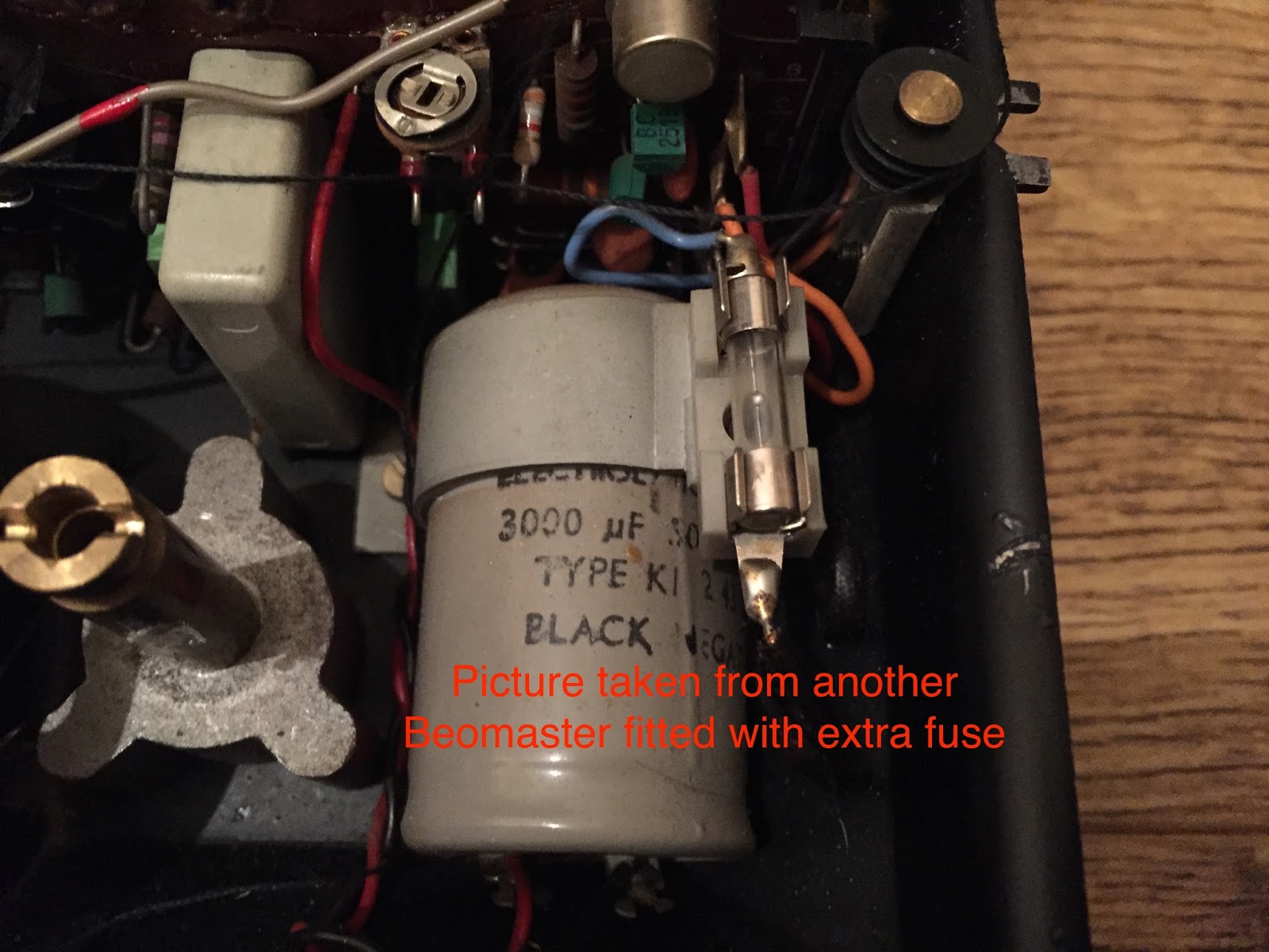
Some Beomaster 6000 quad have an additional fuse of 4A, mounted on top of the bridge holding this 3000 µF capacitor and connected in series with the 27V AC winding. This Beomaster did not have it. It is also not mentioned on any of the electric schematics that I have. I'm thinking of adding this fuse for an extra safety.

The following picture is taken of another Beomaster fitted with this additional fuse. Looking at this picture, it's obvious this was an add-on that was not originally supposed to be there. The B&O engineers must have had some feedback from the service centers after the first series of units were sold........


Time now to connect to the variac and slowly increase the mains supply to see if all is good. Well, hmm, I only got 58,6 V DC out....Should be at more than 60V DC unloaded.


Then I realised that the voltage selector was set on 240V. In the past, my country (Belgium) had 220V on the grid (the UK had 240V), but nowadays Europe is standardised on 230V.  But what I have in my house is more close to 240V (the officially allowed tolerances are +10% and -6%). So, since the voltage selector was set on 240V, I needed to up the variac to  the same 240V. And now I got the required voltage!


With the new trimmers fitted earlier on the power supply PCB, it was now easy the set the stabilised outputs at +18V and -5V.


With this fully operational power supply, I'm now ready to start testing the other boards of this Beomaster.