A healthy body starts with a healthy heart ! This Beomaster's heart is a massive 4kg toroidal transformer with several different windings. The primary windings have the usual connections for 110/120/220/240 volts. The secondary windings have a 27 and 42 volt winding.
The 42V AC goes into a bridge rectifier (mounted just next to the transformer) with a 10.000 µF capacitor, is not stabilised and used for the main power output stages. This 60V DC is further "filtered" through a 100 ohm resistor and 50 µF capacitor to be stabilised into 20V and 21,5V for the electronic switch board.
The same 42V AC is also used to create the high bias voltage needed for the ultrasonic micro receiver. This is done by a simple 3 stage multiplier using diodes and capacitors. Since the ultrasonic micro only needs a static high voltage charge, and not real power/current, this multiplier is sufficient to create a high voltage of about 180V DC. More on the ultrasonic emitter and receiver in a next post.
The 27V AC goes into another bridge rectifier (mounted on the power supply PCB 5) followed by 2 stabilisation circuits to give the required +18V DC and -5V DC. Both these voltages are adjustable through a trimmer on PCB 5.
The transformer was cleaned up and provided with new foam rubbers to fit between the transformer and chassis.


During the first evaluation of this Beomaster (click here), I already noticed some slight buldging of the 10.000 µF capacitor, so time to check. And, no surprise, the capacitor was leaking inside!!

A new one was fitted with the same diameter.

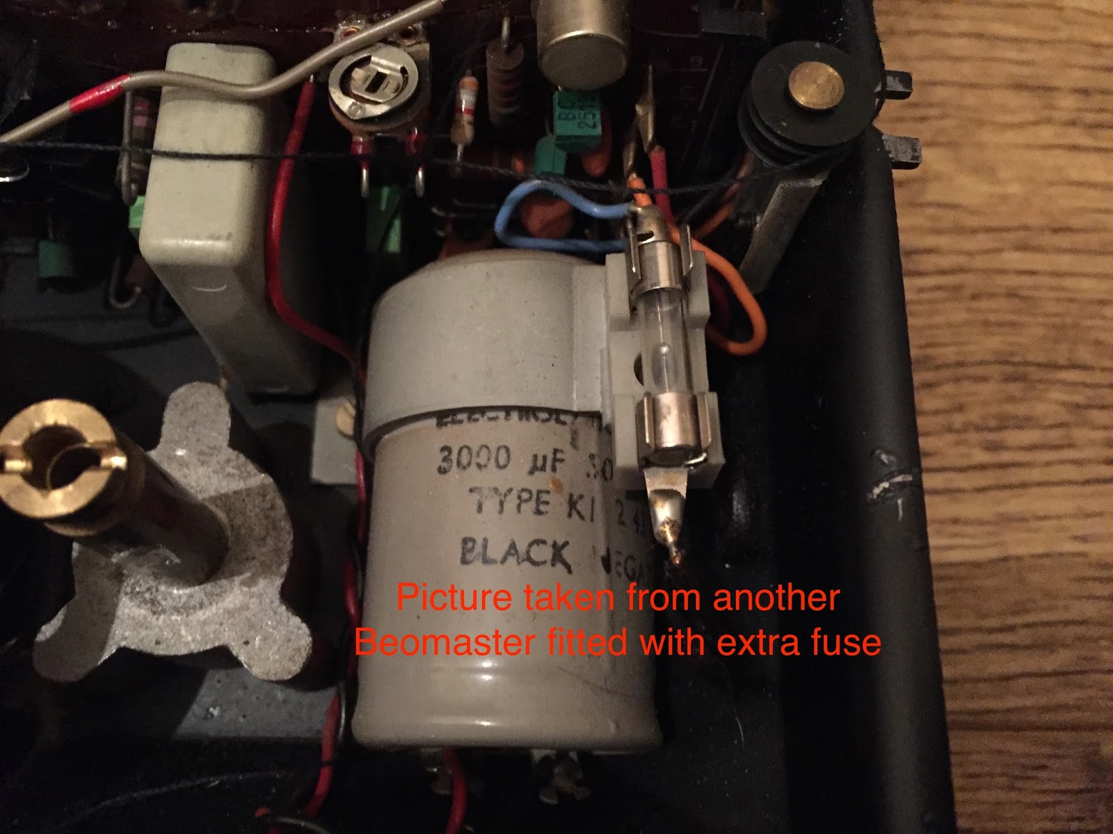
The smaller 3000 µF capacitor for the 18V and -5V was also replaced off course (while this one was not leaking however).

Some Beomaster 6000 quad have an additional fuse of 4A, mounted on top of the bridge holding this 3000 µF capacitor and connected in series with the 27V AC winding. This Beomaster did not have it. It is also not mentioned on any of the electric schematics that I have. I'm thinking of adding this fuse for an extra safety.
The following picture is taken of another Beomaster fitted with this additional fuse. Looking at this picture, it's obvious this was an add-on that was not originally supposed to be there. The B&O engineers must have had some feedback from the service centers after the first series of units were sold........
Time now to connect to the variac and slowly increase the mains supply to see if all is good. Well, hmm, I only got 58,6 V DC out....Should be at more than 60V DC unloaded.

Then I realised that the voltage selector was set on 240V. In the past, my country (Belgium) had 220V on the grid (the UK had 240V), but nowadays Europe is standardised on 230V. But what I have in my house is more close to 240V (the officially allowed tolerances are +10% and -6%). So, since the voltage selector was set on 240V, I needed to up the variac to the same 240V. And now I got the required voltage!

With the new trimmers fitted earlier on the power supply PCB, it was now easy the set the stabilised outputs at +18V and -5V.


With this fully operational power supply, I'm now ready to start testing the other boards of this Beomaster.
No comments:
Post a Comment
Comments and suggestions are welcome!