Featured Post

Beolover SyncDrive: DC Platter Motor Replacement for Beogram 4002 and 4004 (Type 551x and 552x)

Late Beogram 4002 and the 4004 (Types 551x and 552x), which have DC platter motors instead of the earlier synchronous AC motors usually suff...

Showing posts with label wiring. Show all posts

Thursday, January 16, 2025

Beogram 4000: Microsurgery on the Tonearm Wiring

In recent days I made nice progress with the Beogram 4000 from Australia that I have on the bench right now. When I thought I was mostly done I wanted to give it a quick spin to see if any sound would come out of the unit. Unfortunately, I quickly noticed that only one of the channels would produce sound. The other was completely dead.

First I did some measurements between DIN5 pins and cartridge mount connection pads (after preventing the grounding switches from closing with a strip of paper). This yielded that indeed the red (right) channel did not seem to be connected. But I also noticed that blue/green (the signal return wiring) seemed to connect to the center tabs and not the outer ones on the cartridge mount, as would be normal. This suggested that some major 'human creativity' had occurred at some point in the past that changed the tonearm wiring fundamentally. Probably in an attempt to fix this issue.

I did a visual inspection of the wiring, and soon found the root cause for the absent continuity of the right channel: One of the very fine wires that go though the bearing of the tonearm assembly was broken off:

If you look very closely you can actually see the other end of the wire peeking though the thin plastic tube a couple mm from the end of the tube. This meant I needed to find a way to restore the wiring. Luckily, this very thin wiring stretch terminates at the bottom end of the bearing where the wires connect to more solid wires across a small PCB acting as a wire terminal:

I decided to try reconnecting the two wire ends. For this to happen I needed to get the ripped off end inside the tube out in the open, so I could solder the two ends back together. I unsoldered the wires from the terminal PCB and then liberated the plastic tube from the clamp that secures it to the bottom of the carriage assembly:
It turned out that the wires sit fairly loosely inside this tube and I was able to push the broken off wire a bit further into the tube, which happily caused the broken off end to emerge. With fine tweezers I pulled the strand a bit further into the open. These wires are so called 'magnet wire', which means they are insulated by a thin coat of polyurethane. This coat can be burned off in a drop of hot solder at the end of the solder iron tip. A puff of smoke and one has uninsulated wire that can then be soldered. I did this to both ends and then tacked them back together after applying a little bit of flux: 
I then insulated the naked wire stretch with some glue:
I verified that this wire was continuous again and then proceeded identifying which of the wires was connected to what wiring color on the MMC mount. This shows how the colors are connected to the Beolover MMC cartridge mounting tab that I had already installed in this Beogram:
One by one I measured where the thin wires were connected at the tab and then I soldered them to the proper terminal to match the colored wiring on the other side:
This shows the final result on the other end. I had pulled the plastic tube out a bit further than before to give the wires some clearance to the metal bearing shaft, hoping to prevent future damage to them due to reduced stress and no mechanical contact:
I installed the carriage back on its rails and then tried listening to a record again. Happily, the music now came from both speakers, so we can conclude that this issue is fixed. Stay tuned for more details about this restoration effort!


Thursday, April 28, 2022

Beomaster 4400 Type 2419: Reassembly and Power On Test

The hard work restoring this Beomaster 4400 unit is starting to pay off.
I reached the milestone of reassembling the Beomaster and testing its power supplies.

In the last post the Beomaster 4400 reassembly had begun but left off needing the output amplifier transistors to be mounted on the heatsinks. 

The transistors are now installed on the heatsinks with SIL pad thermal insulators.


I also wired up the power switch and mounted an arc suppression device like I usually do with these amplifiers.


The arc suppression device installation required tapping a couple of M3 holes in the Beomaster bracket that secures the large filter capacitors.

I started installing these devices after one Beomaster 4400 had arrived with severely charred switch contacts.  Because these power switches can no longer be sourced (other than stealing on from another Beomaster 4400) I think it is worth a little more effort to protect them.

Before plugging in and turning this Beomaster 4400 on for the first time I plugged it in to my Dim Bulb/Variac tester.

That tester allows me to slowly apply AC power to the Beomaster while monitoring how much current it is drawing.  The light bulb draws current away from the amplifier if too much is present.
Doing that protects the Beomaster from having more component damage if there is a short circuit somewhere.

Here is a good example of why it is good to start out with this type of testing.

This Beomaster started drawing too much current right away as I dialed up the AC voltage on the variac.
It reached about 400mA by the time I was at 50 V.


I stopped and removed power.

After going over the wiring of the Beomaster I found and fixed the problem.

Running the test again I now have a clean power up of the Beomaster unit.


Around 260 mA with full input power applied.
That matches what I get with other Beomaster 4400 units.


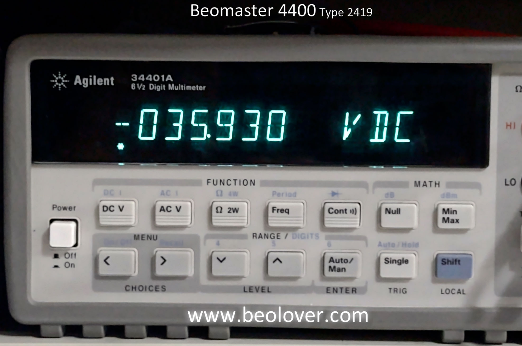
With the Beomaster 4400 able to power on safely I performed a number of power supply voltage checks.

Here are the +15 V and +35 V reference voltages.


Next is the -12 V reference for the audio muting circuit.


Here is the reference voltage for the Phono, Tape 1 and Tape 2 preamplifier circuits.


Here are the 24 V Left and Right channel reference voltages for the preamplifier tone controls.


Here are the power amplifier positive and negative rail voltages.


Finally, here are the Left and Right channel no-load current checks and adjustments for the output amplifier.

The service manual says to measure across the emitter resistors and adjust for between 10 mA and 15 mA.

For now I will roughly set them above 10 mA.  I will adjustment them more precisely later.  Probably at 12 mA.


It feels great to finally have this Beomaster 4400 amplifier powering on again.

In the next post I will start in on some bench testing that is include some actual music listening tests.

Saturday, April 23, 2022

Beomaster 4400 Type 2419: Front Panel Wiring & Reassembly

The last post left off with the Beomaster 4400 ready to have its front panel wired back up to the rest of the Beomaster electronics.

Part of the wiring from the Beomaster 4400 front panel components (switch assembly, PCB 6 and PCB 9) is accomplished with wire harnesses and connectors. Unfortunately there are a few wire connections that B&O left as hard wired. That is what makes the front panel disassembly such a chore.

The task becomes even more difficult if it is necessary to disassemble the switches...like I did in this restoration. That is because wires from the harnesses must be desoldered along with the removal of PCB 6 and PCB 9 to get access to the switches.

Now it is time to put everything back.

One wire re-connection task that does not have a harness or connector is for the speaker selection switches.  The Beomaster 4400 speaker connectors are on the rear panel of the Beomaster cabinet while the speaker select switches are on the front panel.  That is how they should be of course but it means the wiring must travel to and from the switches and connectors.

Here is a photo of the speaker wiring (including the headphone jack wires) and the switch panel board (PCB 9).


Here is a diagram that shows how the wires need to be connection on PCB 9.


This is a photo of the speaker and headphone jack before connecting the wires.


Here is everything wired back up.


Continuing down the front panel from the speaker wiring towards the FM tuning dial assembly I connected the various wire harnesses and individual board to board wires.

This wire harness connects the front panel tone control switches (Mono, Linear, Loudness, Lo Filter, Hi Filter) to the main board tone controls circuitry.
The photo shows the harness before and after being re-connected.


The next series of photos show details of the remaining loose wires that had to be connected.
That includes the wires that are part of the main, PCB 5 harness with the front panel lamps.


Next, I installed the harness with the slider controls (Volume, Bass, Treble, Balance).


Last, I re-installed the main FM tuning assembly.


Here is the Beomaster 4400 with the front panel assembly back in place.


In the next post I will re-mount the output amplifier transistors to the heatsinks, re-install the other PCBs (FM boards and preamplifier board) and re-connect the wires for powering up the Beomaster 4400.