This post summarizes my work on a Beogram 4000 that I received from a customer in Australia for a full restoration. An earlier post discusses the condition of the unit as received.
This shows the unit on my bench in 'service position' after removing platter and aluminum panels:
As usual I first focused on rebuilding the carriage:
I removed all the moving parts of the tonearm lowering mechanism
and liberated the carriage from its rods and spindle:
This shows the removed components ready for the ultrasonic cleaner:
A while ago I realized that the plungers in the arm lowering solenoids often have some residual magnetization. If the magnetization gets too strong the arm will sometimes go up with a delay, which can lead to unhappy needle dragging across the record at the end of a record when the carriage returns home. So I made it a standard item of all my 400x restorations to take the solenoid assembly apart
and demagnetize the plunger. I usually test successful demagnetization with an iron setscrew:
If the setscrew cannot be pulled around with the plunger anymore the magnetization is gone.
While the carriage is up, it is the perfect moment for the removal of the solenoid activated switches and gold plating their contact terminals. This shows the three switch assemblies removed from the carriage:
As usual they were fairly oxidized and also bent out of shape from earlier attempts to fix switch malfunctions.
I usually do the gold plating of these switches together with those found on the carriage position detection board that is mounted underneath the travel of the carriage. So when the carriage is removed, it is also the perfect moment to get to the switches on this board. This shows the board still installed:
Unsoldering of the carriage motor leads and removal of two screws allows to flip this board up revealing the switch terminals and the red solenoid current limiting resistor:
I removed all the terminals from the solenoid and carriage switches for plating:
This shows them after first plating them with a coat of nickel followed by a layer of 24 carat gold/cobalt alloy (such alloys are the standard for gold coatings for electronics applications due to their higher hardness)
Beogolden!...;-). Then I soldered the terminals back into their places. This shows the three solenoid switch assemblies
and the carriage position switches:
I usually also replace the solenoid resistor with a modern higher rated power resistor. These old resistors have a habit of degrading and then getting too hot, with following failure. So it is a good idea replacing them preventatively while this board is up.
With this board out of the way it is a good moment to also replace the solenoid power transistor. Originally it is usually a TIP41A:
I this case it was reduced to being a capacitor:
This immediately explained why the solenoid would not activate when I initially tested the basic functions of this unit. I replaced it with a TIP41C, a higher voltage rated cousin of the A version:
This should help allowing this solenoid transistor to survive longer. This shows the carriage PCB installed back in its place. I also cleaned the plastic switch actuators in my ultrasonic cleaner. As so often, they were caked in old lubricants:
Then I re-installed the solenoid activated switches:
Straight and shiny! Beolovely!
While the carriage is liberated it was also a good moment to replace the MMC cartridge mount. Unfortunately, the cartridge tabs of the 4000 series were made from a plastic that has become brittle in most cases after ~50 years. So it is a good idea to replace the mount before it has a chance to break off when a cartridge is mounted or pulled off. Often the broken off tab remains lodged in the cartridge, which can be a hair-raising moment when it happens with a newly restored $800 cartridge!
It is relatively easy to get the original mount out. After removal of the tonearm, it needs to be 'cooked' for ~30 min at a low simmer:
I transferred the wires to the new part:
and installed it in the arm. It is a good idea to mount the part with a defunct cartridge stuck on the tab. That way the proper position of the assembly inside the aluminum tube is found easily:
After re-connecting the tonearm I replaced the incandescent bulb of the tracking sensor with a LED based assembly. This shows the original black bulb housing still in place:
Removal reveals the aperture used in the tracking mechanism to feedback-control the carriage movement:
The small surface mount LED is in the approximate location of the bulb filament ensuring reliable functioning of the replacement part. This shows the LED assembly installed:
The small white box on top of the assembly is a potentiometer that allows adjusting the intensity of the LED. This can be helpful when adjusting the tracking feedback gain.
Then it was time to put the mechanical components back together. This shows them nice and shiny after ultrasonic cleaning:
This ensures a consistent arm lowering speed. The original gaskets are often hardened and/or warped, which can result in undamped arm lowering. Another hair-riser when an expensive cartridge is on the arm!...;-). As usual for later 4000 (earlier units have an all-metal arm), the solenoid arm extension was cracked in this unit:
This extension is crucial for the functioning of the arm lowering mechanism since it activates the switch that reduces the solenoid power after full extension of the plunger. A loss of this extension would cause the solenoid to overheat and short out. Therefore, I always replace this part with a new
Beolover Solenoid Arm Extension for Beogram 4000:
If you do this at home, please, make sure you fixate the part, bolt and nut in place with some epoxy. This prevents a loosening of the bolt over time as the part gets 'whacked' by the solenoid every time the arm gets lowered.
After the carriage was in place again I re-lubricated the pivot point of the damper-to-arm linkage. This linkage is mounted on the sensor arm assembly in-between the two arms. You can see it stick out towards the back of the turntable from the small V-cut on the metal plate that is bolted to the back of the counterweight assembly:
For cleaning and lubricating the pivot point the sensor arm needs to be removed. Here you can see it extracted with the linkage already removed:
Af course the small copper plate that helps lateral movement of the tonearm while it is up was loose due to degraded double sided tape. I cleaned the little plate
and reinstalled it with a dab of epoxy.

The final 'act' of the carriage restoration was the replacement of the incandescent light bulb in the record detection sensor at the end of the sensor arm. This shows the small sensor compartment pulled out with the bulb still installed:
Then it was time to restore the PCBs. First came the main PCB:
Someone already replaced the original Siemens relay:
I started with replacing the one electrolytic capacitor on the solder side:
Here a picture of the new one:
Then I replaced all the other electrolytic capacitors, power transistors, relay, RPM trimmers and sensor arm transistor:
While the PCB is up, it is a great moment for also replacing the two push-pull TIP31/32 Darlington transistors that drive the AC motor. They are bolted to the enclosure bottom for enhanced heat transfer:
It immediately became clear why the AC platter motor ran intermittently when I first plugged this unit in. One of the pins was broken off inside the yellow insulation tube:
I replaced the two transistors with stronger TIP41/42 for enhanced longevity:
Then I replaced the two electrolytic capacitors on the power supply board and also the sole power transistor on this board:
Next up was were the AC platter motor and the big capacitor cans that serve as power rail reservoirs or to shift the phase of the second motor phase:
I removed everything:
This shows the extracted motor:
I took it apart
and submerged the two clamshell housing parts in synthetic oil. I pulled a vacuum to start the oil infusion of the bearings that are integrated into the clamshells. Immediately strong bubbling and foaming occurred in the oil container:
This process can take up to three days until the bearings are fully replenished. In the meantime I focused on the remaining restoration tasks. At this point most items inside the enclosure were unbolted. So it was a good moment to install new transport lock bushings. The old ones were completely degraded:
This shows the Beogram ready for vacuuming out the enclosure:
The degraded transport lock bushings had turned into a powdery mess:
I designed them in two halves, which makes installation very simple. Just push one half in to the orifice from below
and then the other from the top:
If you try this at home, please, note that some Beograms have slightly larger orifices, which may make it advisable to add a small amount of superglue gel to hold the parts in place. This shows one of the bushings with the lock screw already in place:
This part not only replaces the large capacitor cans, it also updates the main power supply of the Beogram, the 24V rail, with a modern buck converter that significantly reduces the energy consumption of the deck and with that also the fairly high heat emissions. Installation is made simple by the clearly labeled contact pads on the assembly. First I soldered the leads from the two 2200uF cans to the pads on the upper half of the board:
Next came the leads that were originally soldered to the reservoir capacitors on the other end of the board:
The oil infusion of the motor had come to completion in the meantime. I re-assembled the motor
and then soldered its four leads to the board:
At this point the board was ready to be bolted in:
The board bolts to the original mounting holes that were used for holding the original capacitors in place.
My next focus was the keypad assembly. It contains an early digital control system that manages the functions of the Beogram. After taking out the sole screw that holds it down I removed it and flipped it over. I saw that the strobe mirror had been already glued back in place. It seemed a solid connection, so I left it untouched:
I also noticed that the lower PCB had been unbolted from its hinge (which allows it to be flipped vertically for service). Luckily the hinge part and the two screws were still in place:
I reassembled the hinge and then put the keypad into service position. This shows the upper PCB that holds all the switch terminals for the keypad. As usually they were very oxidized:
The flipped up board holds most of the digital gate ICs and the light bulbs that illuminate the carriage position indicator and the two RPM trimmers. What I found explains the blueish sheen that came from the position indicator compartment when I initially tested the Beogram. Someone had installed three cold white LEDs:
I focused first on the switch terminals. I extracted them for gold plating. Very oxidized indeed!:
This is how they looked after I coated them with nickel and gold:
Much Beolovlier!...;-).
This shows them re-installed:
Then I replaced the three LEDs and the remaining original bulb with LEDs. This shows the
LEDs I use for the backlighting of the RPM trimmers:
They need to be installed with current limiting resistors since they run on the 12V bulb voltage. For the position indicator backlighting I used the
Beolover Scale Illumination LEDs for Beogram 4000 LED assemblies. This shows everything implanted:
and lit up:
At this point I also adjusted the bias for the sensor arm transistor to yield a DC voltage of ~1.8V at its collector:
After this adjustment I moved the bias trimmer to the component side.
Then I reinstalled the plinth after bending its mounting tabs back into proper shape. As usual the plinth washers were mostly cracked
The black one is for the front center fixture so it cannot be seen when the aluminum panels are installed. This shows one of them installed:
The next step was doing all the mechanical adjustments:
First I aligned the arms to be parallel and in 23mm distance from the platter. Then I aligned the floating sub chassis to make the platter flush with the aluminum surfaces. Next came centering the platter inside the opening in the large aluminum panel. This is done by carefully bending the threaded rods that control the tension in the leaf springs that float the chassis. All this can be a pretty tedious process and require a few iterations to get everything perfectly into place.
Usually, the next step after getting the platter and subchassis adjusted is setting the arm lowering limit and calibrating the tracking weight.
Unfortunately, I realized at this point that the arms after returning home when pressing OFF would not stay home but travel back towards the record for an inch or so until they would stop.
After a bit of thinking I realized that the culprit might be a 24V reed relay in permanent closed position causing the 24V rail to stay on after the carriage hits the off switch at the home position.
A quick check with the multimeter confirmed my suspicion. The relay was closed even with the deck unplugged. So I extracted it from the coil:
This shows the new one installed (top relay in the lower yellow coil):
For more details on the process, please see
here.
This fixed the issue and the Beogram behaved normally again.
Now it was finally time to do the remaining adjustments.
First I focused on the tracking weight calibration. I usually replace the flimsy locking washer on the counter weight screw
with a M3 nut and a washer:
The nut allows locking the calibration in place to survive the rigors of the shipping process.
This shows the final calibration:
I usually try to get the weight calibrated around the 1.2g setting on the small rotary dial next to the arm base. Most B&O cartridges seem to require 1.2g tracking weight. These dials are notorious for showing imprecise weight numbers. In general it is best to use a digital scale for calibrating the weight occasionally regardless the setting of the rotary dial.
Next came the adjustment of the tracking feedback gain to ensure proper tracking of the grooves during the advancement of the tonearm towards the center:
After completing the adjustments I installed a new all-metal DIN5 plug with gold plated contact pins:
This measurement (done in the 'slow' mode of the BeoloverRPM) yielded this 24 hrs RPM stability curve:
This curve shows the typical thermal drift that is typical for analog control systems. My workshop in Albuquerque changes temperature quite a bit during the night in winter due to the often freezing outside temperatures. The dip in the graph above corresponds with the unheated night hours in that room. Overall this curve is as good as it gets with the Beorgam 4000!
The BeoloverRPM has a second mode, 'fast', where it puts out one RPM measurement per platter rib passing under the sensor. This allows a high resolution measurement that allows the determination of 'wow and flutter', in other words RPM changes that occur on a short timescale.
The fast mode usually results in an RPM graph that shows a repeating pattern:
This pattern repeats every 24 measurements, i.e. corresponds to the turns of the platter (the platters have 24 ribs on them. Every platter yields a different pattern suggesting that this pattern is a measurement artifact. Indeed there are small differences in the rib spacing around the platters due to manufacturing tolerances and this imprints a pattern on the RPM measurement. This graph shows the pattern for about 50 latter turns:
The slight superimposed waviness of the pattern actually corresponds to real RPM changes caused by the elastic coupling between platter and motor and fluctuations in the precision Wien oscillator itself that drives the synchronous motor. These fluctuations are well below the 0.05% RPM variations specified in the Beogram 4000 service manual. So all good in the RPM department of this Beogram!
Not all good was the record detection department. After the above test I did my usual test with an empty rotating platter to see if it would properly detect that there is no record. It did not and eagerly dropped the needle onto the platter! It turned out that the photocell in the sensor compartment at the end of the sensor arm had delaminated. I extracted the defect cell:
It is a direct plug-and-play replacement for the original cell, i.e. there are no circuit modifications necessary to make this work. This picture shows it installed:
A very good signal with a 2.5V amplitude. More than what the manual specifies. A test with an empty platter confirmed that the record detection mechanism indeed was restored.
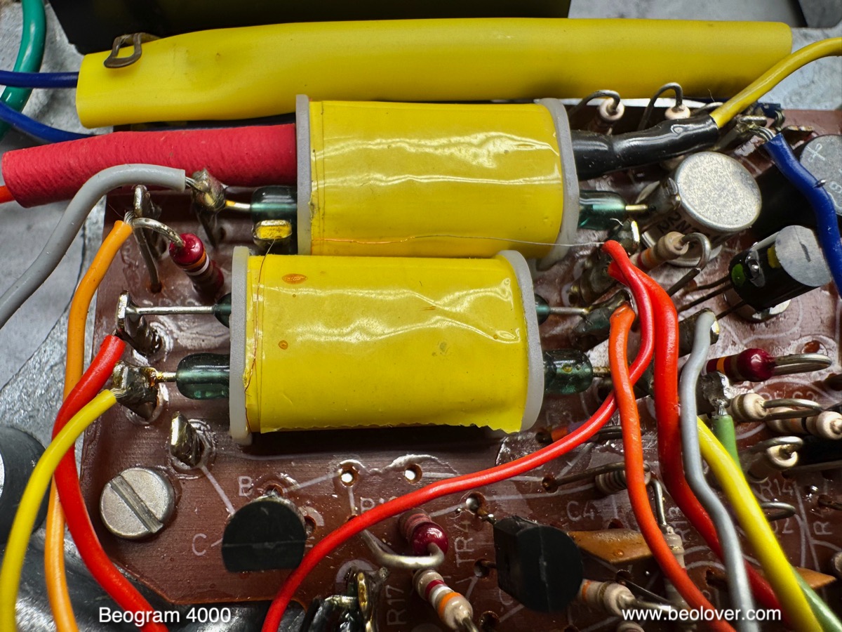
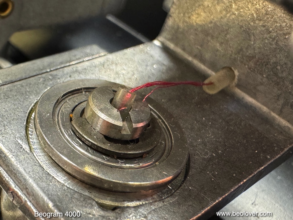
At this point I finally tried to play a record. It played, but only on one channel. Closer inspection yielded that one of the thin wires that connects the tonearm had broken off:
I was able to solder the two wire pieces together, which restored the second channel:
Please, read my dedicated post about
this microsurgery for more details about the process.
Now it was finally time to install the
Beolover internal RIAA pre-amplifier for Beogram 4000. It is a pretty simple installation process. It connects directly to the output terminals of the Beogram and the output cable only needs to be transferred unmodified to the equally spaced output terminals of the RIAA board. This shows it installed:
Read more about the installation process
here. The board can be switched between RIAA amplified and un-amplified standard signal routing. This means after installation the deck can be directly used with any high-level input like DVD, CD, AUX or any modern boombox with a line input, while it also can still be used with a dedicated Phono input.
And then it was finally time to enjoy a first record on this beautiful fully functionally restored Beogram 4000! I chose a recent acquisition, a pretty awesome record released 1972 by the Ramsey Lewis Trio on Columbia Records (
KC 31096). I bought this record as 'bycatch' when I was ordering another record on discogs and free shipping was offered by the seller for a couple more records from his store. And so I went through the collection and fund this one. I am happy I did! It has a very interesting rendition of one of my favorite tunes, People Make the World Go Round on side one.
Of course this record was cleaned on a
CleanerVinyl ProXL setup to restore its original glory.
Here an impression of this lovely album playing on the Beogram:
Absolutely satisfying! I will now play this Beogram 4000 in my shop for some time while we wait for the arrival of a new CNC precision machined teak wood frame provided by
Christian Hakansson's workshop. Unfortunately, the original plinth is damaged on the front left corner. Walk more carefully, people, when you carry your Beogram around!..;-). Stay tuned for an update!