Featured Post

Beolover SyncDrive: DC Platter Motor Replacement for Beogram 4002 and 4004 (Type 551x and 552x)

Late Beogram 4002 and the 4004 (Types 551x and 552x), which have DC platter motors instead of the earlier synchronous AC motors usually suff...

Showing posts with label PCB 1. Show all posts

Saturday, July 10, 2021

Beogram 4004 for the Workshop: Surprise addition of the Beolover Commander Remote Control !

Since the last post for this project I successfully ran some listening tests.  This Beogram 4004 plays records beautifully again so I was ready to reattach the deck panels and listen to more records.

However...I received an amazing surprise...a preliminary version of the latest Beolover 4002/4 Commander Remote Control.

On more than one Beogram 4004 restoration project in the past I was asked by people if the restoration could include the Beolover Commander Remote Control.  Unfortunately the answer was no.  The initial version only supported the Beogram 4002 type turntables. That is now changed as this latest version includes support of the Beogram 4004. There was good reason the earlier Commander didn't support the Beogram 4004 and I will talk about that when I show the installation below.

But first, here is this Beogram 4004 with the deck panels and tonearm cover back in place.


If you look at a lot of our other blog posts of Beogram 4002/4004 restoration projects you will see that installing the deck panels includes the tedious task of adjusting the floating chassis springs.  Both the height of the platter and the centering of the platter within the deck opening can require a lot of iterations.  This Beogram was no exception but I was finally satisfied with the result.

Here is a view from the top. It includes the tools I used to get everything aligned.


Now for the special surprise of the Beolover Commander Remote Control.

The Beolover 4002/4 Commander Remote Control comes with a main board component that has the IR receiver attached as well as an LED indicator for the Beogram speed control panel.  The Commander also includes the Beogram 4004 PCB 8 connector adapter and of course the remote control itself.


Here is a closer look.
The Commander came with its board jumpers set for a Beogram 4002.  I moved the three jumpers over to the Beogram 4004 position as that is the mode I will be using the Commander.


To go along with that mode the Beogram 4004 PCB 8 adapter connector is attached to the main Commander board at the connector marked "to 4004 output board".


Now for the installation.

As I mentioned above, the original Beolover 4002 Commander did not support a Beogram 4004 turntable.  The reason is because the Beogram 4004 turntables have a different wiring harness on the button control panel.  The Beogram 4004 PCB 8 output board has an early Bang & Olufsen remote control circuit that is designed to integrate with the remote control system of the Beomaster 2400.  That remote control integration between the Beogram and Beomaster is a wired connection via pins 6 and 7 of the phono DIN connector. 

While the original Beogram 4004 and Beomaster 2400 remote control functionality is nice, it is limited to Play, Stop, Cue Up and Cue Down.  It has no forward or reverse scanning.

The Beolover 4002/4 Commander Remote Control has Play, Stop, Cue Up, Cue Down, Scan Forward, Scan Reverse and Repeat play. The scanning control also supports slow and fast scanning.

The first part of the Commander installation is to insert the Beogram 4004 PCB 8 adapter connector.


The PCB 1 mounting screw shown below will be used to attach the Commander main board to the Beogram 4004 main board.


The Commander main board connector male pins fit into the Beogram 4004 PCB 1 connector for the button control panel.

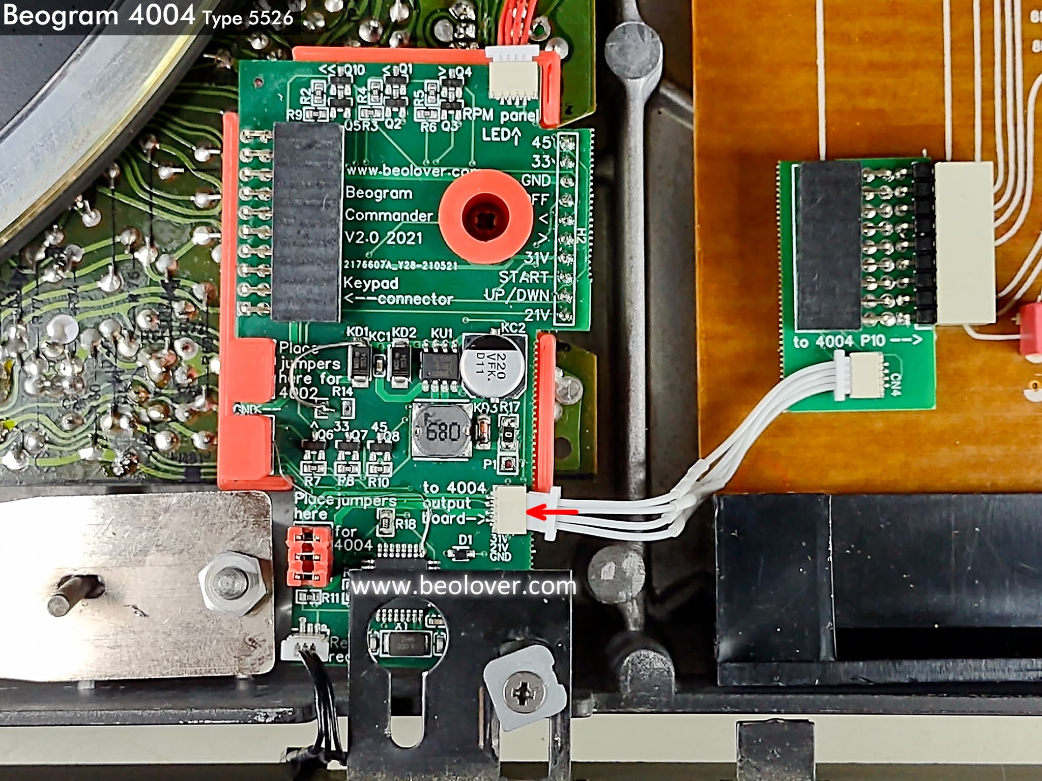


The Beogram 4004 button control panel connector for PCB 8 now plugs into the Commander adapter.


The other connector of the Beogram 4004 button control panel harness plugs into the connector on the Commander main board.


The small LED board and harness is installed in the Beogram speed indicator panel.


The Commander system is now installed.


The little IR sensor peeks out from under the trim in the front of the Beogram...ready to detect commands from the remote control unit.


But does it work?

Of course.


Very nice. 
Having played around with the remote control functions of the Beomaster 2400/Beogram 4004 system I can say the added capability of the Beolover 4002/4 Commander are quite a welcome addition.  Highly recommended :-).

Monday, July 5, 2021

Beogram 4004 for the Workshop: Measurements & Adjustments

After performing the restoration work on the two boards, PCB 1 and PCB 8 I moved to checking the voltages on 1TR3 collector for the record detection circuit and on 4IC1 collector for the position sensor.
The new 1R26 5MΩ trimmer will be used to set the voltage on the 1TR3 collector to 4 VDC.  The 1R88 trimmer will be used to set the voltage on the 4IC1 collector to 5 VDC (when the sensor is getting its light stimulus through a clear part of the position scale).

Here is the position sensor adjusted.


Here is the record detection circuit adjusted.


Trimmer 1R26 can now be desoldered and soldered in place on the other side of the PCB 1 board.

I will double-check the actual record detection waveform on an oscilloscope later but first...
I need to do some work on the tangential arm assembly.

This Beogram 4004 turntable is in really great condition but I did notice during the assessment checks that the platter motor and the tangential arm servo motor make a lot more noise that normal.

The platter motor being noisy isn't too surprising given that they often are lacking oil in their sintered bearings (self-lubricating bearings). That happens after 30 years.
Whenever I have sent Beolover some Beogram 400x platter motors for restoration I often send along a couple of my own.  That worked out nicely here as I have a nice Beogram 4002/4004 DC platter all nicely restored by Beolover to swap out with this noisy one. Note that this one is marked serial number 1947049. 


Of course the restored DC platter motor is super quiet.  There is still the tangential arm servo motor though.  It was making the most noise.  Especially when the arm was returning to the stop position.

I removed the servo motor from this Beogram and tested it with a bench power supply to see if the motor was still noisy when out of the Beogram chassis.  It definitely was.  Even at slow speed.
The servo motor is sealed and isn't a motor Beolover currently offers a rebuild for so I grabbed a spare servo motor and figured that would be a quick and easy swap.

It turned out not to be the case. The next three servo motors I tried were all too noisy for my liking.
I finally found a nice quiet one from a Beogram 4002 turntable.

Here is a photo of the four noisy servo motors.


Along with the good, quiet, replacement servo motor I installed a new aluminum tangential arm pulley for the Beogram 4004 spindle assembly.


Even though I didn't photograph the spindle cleaning and lubrication I took this opportunity to perform that task as well. I used the same lubricants as I used on my other Beogram 400x restorations.


A mixture of the NUTO H32 and Rocol MTS 2000 is used for the spindle lubrication.
I use the DX Paste Grease for the front tangential arm rail.

The next set of tasks were to get the Beogram 4004 tangential arm assembly checked and adjusted.
- First thing is to set the platter height where the surface of the top platter is 23mm below the top of the fixed arm assembly.
- Second thing is to set the lowering limit of the tonearm so the phono stylus is about 1mm above the lower platter rib section.
- Third is to calibrate the phono cartridge tracking force.

Platter height


Stylus lowering limit


Tracking Force Calibrated
I calibrate the tracking force at the 1 gram position as it is the most commonly used.


I use threadlocking Loctite for the adjustment screws so they can't move during any vibrations the turntable might experience (like transporting).


Now that the tangential arm components are adjusted to their correct positions I can set the tracking sensor sensitivity.

The position sensor, tracking sensor and record detector sensor lamps on this Beogram are all still functioning good so I decided to leave them as is for now. 


Remarkably the tracking sensor was already very close to a proper adjustment. It only required a small tweak of the eccentric adjustment screw to fine tune the setting.  

I reinstalled the platter on the Beogram and adjusted the two speeds using the Beolover RPM tool.
The platter motor silently and easily adjusted for the two speeds.


Now that the platter spins properly I checked the record detection sensor signal when no platter is present.


The record detection circuit is a good solid signal at 33.333 and 45 RPM platter speeds.  The low part of the signal goes all the way to zero volts which is what I am expecting.

Last on the task list for this post is to replace the platter speed indicator lamps with the Beolover LED lamp assemblies. It is always worth mentioning that these lamps are part of the Beogram platter speed control circuit and do affect that performance.  Beolover has measured an increased stability in the platter speed control with these LED assemblies over the original incandescent lamps.  The Beolover LED assembly is designed to work with the speed control circuit the same as the incandescent lamp but without changes due to lamps heating up.

Here is the Beogram 4004 speed indicator panel.


Here is a look at one of the Beolover Beogram 4002/4004 indicator lamp assemblies. 
They come as a set of two (left sided mount and right sided mount).


The LED lamp assemblies are soldered in place and some included double-sided tape helps secure the small boards to the panel.


The speed indicator board is complete and ready to reinstall.


This Beogram 4004 is ready to start playing some records.

Saturday, July 3, 2021

Beogram 4004 for the Workshop: PCB 1 & PCB 8

In this post I performed the restoration work on the main board (PCB 1) and the output board (PCB 8).

However, I started off the capacitor replacement in the cabinet with the power supply 4000uF filter capacitor.  I replaced the old electrolytic capacitor with a new Nichicon electrolytic capacitor in Beolover's 3D printed housing. The power supply filter capacitor style changed on various types of Beogram 400x turntables. This Type 5526 Beogram 4004 uses a single filter capacitor.


Next I started in on removing the main board and the output board for their restorations.
While doing that I did some more assessment on other components inside this Beogram.
The button control panel works fine but I can see that the switch contacts will likely need some cleaning. 

It is necessary to remove the button panel and disconnect three cable connections to get to the output board (PCB 8).

PCB 8 contains the audio (from the phono cartridge) signals to the phono cable going to a preamplifier.
There is an audio muting circuit there that switches the audio signals (Left & Right) to ground when the phono signal is muted.

PCB 8 also contains an early remote control system between a Beomaster 2400 and a Beogram turntable.  The Beomaster 2400 contains the actual remote control.  It uses an additional two pins in the phono cable DIN connector (pins 6 & 7) for the wired remote control integration with the Beogram 4004.


PCB 1 is the main board and contains all of the Beogram analog control circuits.


I removed the boards from the cabinet to do the restoration work on them.
I usually begin with the PCB 8 output board because it is smaller and easy to do first.

Again, the audio output/muting circuit is highlighted along with the remote control circuit.
One thing a little interesting on the audio output circuit is the signal ground and system ground connections on the output cable connector.  Some Beogram 4002/4004 turntable PCB 8 boards have a small capacitor (8C2, 47nF) between those pins.  This Beogram 4004 has that capacitor removed.  I have seen this on several Beogram 4004 units and I am not sure whether there was some B&O service bulletin about it or not.


Since this PCB 8 board had 8C2 removed I decided to use those PCB holes to mount a small toggle switch that will connect/disconnect signal ground withe system ground.  This can be used to make that selection choice when addressing any hum in the phono signal between the Beogram 4004 and an amplifier.

Here is the reworked board.
I replaced all of the electrolytic and tantalum capacitors 4.7uF and smaller with WIMA MKS non-polarized capacitors.  I also replaced the original, National muting relay with the Beolover Omron replacement.


That takes care of the output board.
Now on to the main board.


I used the same strategy on the capacitor replacement but I should note the in many cases, including this one, I have found that the existing tantalum capacitors are often still good. I still like replacing them with WIMA non-polarized capacitors as that should mean one less thing to worry about in the future. Preventative maintenance I believe it is called :-).
Many times however, we get Beogram control boards from units that were not stored in good environments so we definitely want to change the tantalums and electrolytic capacitors in that case.

I will change out two trimmer resistors on this board.  1R15 (33 1/3 RPM adjustment trimmer) and 1R14 (45 RPM adjustment trimmer).  The speed selection relay will also be changed from the original National relay to the Beolover Omron replacement.  Beolover has demonstrated many times that these replacements are effective in platter speed consistency along with the platter motor restoration.


Another main board change is resistor 1R26 and transistor 1TR3.
Those are key in the Beogram 4002/4004 fixed arm sensor's record detection circuit.
For long term reliability and stability we check the transistor gain to see that it is at least 500.
If not we change the transistor to a new one that is.  The 1MΩ 1R26 resistor is changed to a 5MΩ trimmer resistor. Together with the 500 Hfe 1TR3 transistor it will be easy to set the steady state voltage level of 1TR3 so the Beogram 4004 record detection circuit operates at its optimum capability.


In this case the original 1TR3 has a gain of under 500 so I went ahead and changed it.  The Beogram record detection still worked without this change but I make the change because it will be more reliable in the future. 


The replacement transistor has the collector and emitter leads reversed with respect to the transistor case shape.  It is always a good idea to test and check that the orientation of a new transistor matches the original one.


Here is what the new 1R26 and 1TR3 will look like installed in the PCB 1 board.


I soldered the 1TR3 transistor but I will temporarily mount the 1R26 trimmer on the trace side of PCB 1 so I can easily make the setting of the resistance value.  Once I have that dialed in I will remount the trimmer as shown above.

Here is the reworked PCB 1 board.


Here is the trace side with the 1R26 trimmer temporarily installed for adjustment.
I also placed two PCB 1 capacitors on the trace side so they can't interfere with the floating chassis movement.  They sit right above the floating chassis so these WIMA replacements are better on the PCB 1 trace side where they will be out of the way.


That does it for the PCB 1 and PCB 8 restoration work.
The next step will be to reinstall the boards and do some initial voltage checks.