Featured Post

Beolover SyncDrive: DC Platter Motor Replacement for Beogram 4002 and 4004 (Type 551x and 552x)

Late Beogram 4002 and the 4004 (Types 551x and 552x), which have DC platter motors instead of the earlier synchronous AC motors usually suff...

Showing posts with label stage. Show all posts

Tuesday, January 30, 2018

Beomaster 6000 (2702) restoration: re-assembling the output subframe

Before putting the output stage PCB back into the subframe there are a few things to take care of. First is cleaning the frame, the heat sinks and the plastic spacers. To remove the glue on the frame I used paint remover followed by some alcohol cleaner and water with detergent. I looks almost as new again!


And after the cleaning...


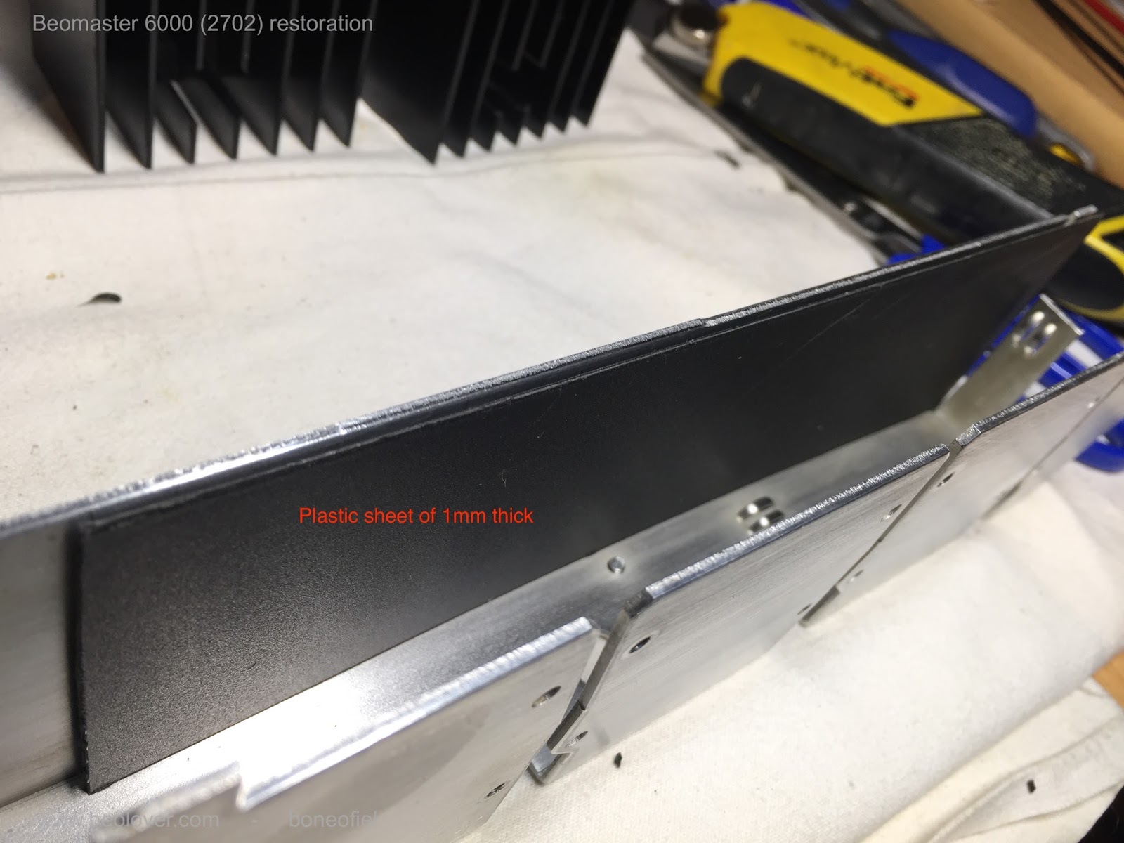
The warping of the output PCB has been mentioned a few times already and to avoid the common short circuits between the subframe and the solder side of the PCB I decided to use a permanent shielding in between. I used a sheet of 1mm thick plastic that I cut to size and glued on the inside of the subframe. Several cut-outs need to be done off course to fit everything back later and to give the wires, screws, etc. the space they need.


When I mounted the PCB I noticed something interesting:  the warping of the PCB was almost completely gone. The reason is simple: the many wires that come from the 8 darlingtons transistors are longer than needed (to allow removal without desoldering) and are "stored" on the bottom of the subframe when everything is mounted. This cable tree however pushes against the board and makes it warp. There are tiny slots on the bottom of the frame (see picture above) that are supposed to hold the board in place. But they are to small and the board jumps out easily. As a precaution (probably not really needed) I glued a small plastic spacer on the board in order to keep the correct distance between board and frame. Again, probably not needed but it helps to get a perfectly aligned and straight board and that looks nice!


Up to the the heat sinks and the output darlington transistors. To make mounting easier and avoid breaking of,  I replaced all the hard wires going the 8 darlingtons and the 4 transistors (that are also mounted on the heat sinks) with flexible wires. AWG 20 (0,5mm²) for the power darlingtons and AWG 24 (0,2mm²) for the other transistors. I tried to respect the original color code and was able to keep all but one original color. Note that the wires all have different lengths !


The mica isolators that are typically used are replaced with sil(icone)-pads. Some of the originals ones where cracked anyhow as you can see in the picture below. I know there is some debate about the pro's and con's of both. Some people stick to mica and use the needed thermal paste. Other swear to silpads. I'm in favour of the latter. It's easier and less messy since you don't need the white thermal paste anymore. I agree that one needs to be careful. These silpads can be punctured if something  (like a tiny ball of solder) sticks between the transistor and frame (heat sink). Therefore it is wise to check the surface smoothness of the transistor (usually the collector connection) and the frame. Also, do not over-tighten the bolts or screws. 


The plastic spacers are fixed to the subframe with a dot of glue, just enough to keep them in place.


The small driver transistors that are used for feedback of temperature and thus allow thermal stability of the power stage (the bias current) do need a bit of thermal paste since they are to small for silpads. One of them was fried on the right output channel and I replaced it with a authorised replacement (MPSA13).


Now all the heatsinks and transistors are mounted on the subframe.


Before moving on to the next phase, I checked a few things to make sure that there was no shortcircuit anywhere, that I had not mixed up the NPN & PNP darlingtons, etc. I found a fault in (again) the front right channel. Something was not measuring correctly. So I had to remove the board again and found a burned resistor 11R69 of 330 ohm that I had not noticed before.  This resistor is in series with the trimmer that regulates the bias current. I did replace all the trimmers before but never checked them for burning out. I did now, and one off course was burned out. Normal, since the driver transistor O1C6 was short circuit on all tree connections!

should be "resistor" of course and not "transisitor"

Checked again and so far so good. But no power yet applied to the board. That's for later.....

Saturday, October 10, 2015

Beomaster 8000: Rebuilding the Outputs, A New Interesting Output Failure Mode, and First Startup

I started working on the Beomaster 8000 that I recently acquired via eBay on behalf of an B&O enthusiast in the UK. The 8000 is definitely one of my most favorite restoration projects. An absolutely awesome design. The Beomaster 8000 was sold under the premise to be fully working but to have had some 'amplifier trouble', which supposedly had been 'professionally' repaired. Oh well, I heard such claims before, and especially on eBay the unsuspecting buyer needs to be aware that there are not many repair outfits left who can or want to tackle these units. Instead there is a lot of amateurish effort going on with the aim to make a fast buck and turn these sought-after units around for a ransom 'in restored condition'.

With that in mind I approached this Beomaster with caution and gave it my usual 'fix outputs first and then turn it on' treatment. So I opened it up and found a fairly clean situation. However, three screws are missing under the speaker switch cover:
And the cardboard shield that is supposed to keep the solder points on the display board from shorting against the toroidal transformer was installed incorrectly:
An interesting feature is the late-series microprocessor board that has soldered on EMI can lids and a sticker that says 'Sealed unit. To be returned to the distributor for service'...we'll see to that...;-)

After I lifted the display/uProcessor boards into service position and took the input socket panel tray out I looked at the output PCBs. And I made an interesting find: The quiescent current trimmers were replaced on both channels with 47 Ohm resistors. A very creative, but questionable fix to the corroding trimmer problem that commonly leads to frying the transistors in one or both outputs when the trimmers go open circuit. Here is a picture of the left channel board:

The resistor in question is in front of the third electrolytic cap from the left. Very crafty! I hooked the right channel board up with three external power supplies providing the ±55V rails and the 15V control bias:

The multimeter shows the voltage across the two emitter resistors R236/7 as 4.7mV. This is much lower than the prescribed 18mV. Well, at least the 47 Ohm resistor errs on the 'better side' by running the output Darlingtons IC203/204 at a too low operating point. Had the 'expert' who did this elected to use the next standard resistor value of 56 Ohms, most likely the unit would have run pretty hot. The problem with running at a too low operating point is that class B amplifier cross-over distortion is introduced in the output signal since the two half-waves are not 'connecting' smoothly at the cross over point. Since all TIP141/146 pairs are slightly different, trimmers are needed to find the perfect operating point for each unit independently. 

I installed as usual 25 turn encapsulated 100 Ohm precision trimmers
in both of the output boards and also exchanged all the electrolytic capacitors with 105C level quality Japanese units. This shows the left channel:
And here is the right:
Then I ran the right board with my external supplies and adjusted the trimmer to yield 18mV across the emitter resistors:
The power supplies showed the usual 0.11A (-55V), 0.1A (+55) and a close to zero current on the 15V control voltage pin


Very good! Then I did the same for the left channel, and I was surprised: No matter to what value I would set the trimmer, the multimeter would show zero voltage across the emitter resistors. Something was not working!
I poked around and measured the voltages across the TIP141 and TIP146 'columns' in the output. The voltages seemed reasonably close to the values shown in the service manual. Very strange! Then I measured the voltage at the base of the npn Darlington (IC203) while turning the potentiometer. Nothing happened. It stayed constant at about 1V. This was strange, since the potentiometer is supposed to adjust this voltage to about 1.2V to set the operation point of the Darlington. I did the same at its pnp match (IC204) and this base changed the voltage depending on the trimmer setting. A bit of head scratching lead me to the root cause of this phenomenon: The yellow lead between the emitter of IC203 and the PCB was open circuit. I unsoldered the lead and found that it was only hanging on by a shred of insulation, but that the wire had disconnected:
I took some insulation off and soldered the lead back in, and then everything was as it should be.
Time to plug this baby in and finally turn it on:
Allright! First light! This marks the start of another Beolover restoration!


Saturday, August 2, 2014

Beomaster 8000: Restoration of the Output Amplifiers

As usual, I rebuilt and tested the output amplifiers (PCB #5) of the current Beomaster 8000 restoration project before turning it on the first time. While the ebay seller claimed it was 'fully working' there is always a chance that one of the output trimmers goes non-contact during transport, i.e. in my opinion it is worthwhile to do the outputs first and test them with external power supplies (see here for a description of the process: http://beolover.blogspot.com/2011/09/output-stages-testrecap.html).
This takes a bit longer, but definitely saves a lot of cost and effort compared to replacing the output transistors. Anyway, here are the before and after pictures...:

Left amplifier before: 


after:


Right amplifier before:


after:


It was definitely a good idea to replace the caps, most were cracked. Here is a picture of one of the 220uF caps:


I measured the capacitance and ESR of these caps, and they were still all in spec...pretty amazing, considering the cracks...it seems the capacitor situation depends a lot on how the individual Beomaster was stored/treated, and whether it was used regularly etc...

When testing the boards, the external power supplies showed the following currents after adjusting to 18 mV for both boards:

+54V--> 0.10A
-54V-->0.11A
+15V-->0.01A

This all made sense, so I reconnected the output rails and fired the Beomaster up. It came on with a healthy double relay click and then showed a nicely working display. It seems all segments are working - also pretty amazing, considering the 'white PCB' style of the displays. I guess it was really treated well in its pre-eBay life!
I easily tuned into my favorite local radio station and enjoyed a bit of their NPR programming. The only issue I could find during this brief first test was a not working 'filters' light...hopefully this is just a light bulb.

On to the power supply.

Monday, July 28, 2014

Beomaster 8000: First Look Inside

It seems the last Beomaster 8000 is now happy, and I put it back together. It went to the living room for a few weeks of testing amongst his friends the Beogram 8000 and the Beocord 9000.
Time to open up the next 8000 in line! This one is very nice on the outside, and the interior is not different. While it was opened up before (slight screwdriver mark on the glass cover - still have to see an 8000 without...it is definitely a good idea to protect this corner with some tape before opening them up...). There is also an about 15 year old cap in there (6C35 to control the 5V ripple after the voltage regulator). But whoever did it put it back together properly...all screws the right sizes, nothing missing, even the small copper damper for the control panel door release is in its proper place.

Otherwise, it is as original as it gets upon visual inspection. Also very clean. Almost no dust! Very nice! Check out this left channel output board: Almost as it were recently put in a cleaning bath:


But, appropriate for the age, two of the red electrolytic caps are cracked, indicating that a full recap is probably a good idea. The output resistors are non-browned, which makes me hopeful that it really still worked as it was advertised on ebay.

The displays are unfortunately pre-solder mask style, as is evident from the whitish epoxy boards:


We will see how the segments are when I turn it on the first time. Experience tells me that this style displays is prone to segment failure. It seems that displays with the greenish epoxy boards may be more stable over time.

Next step: As usual, I will rebuild and test the output stages before the first turn on.