Featured Post

Beolover SyncDrive: DC Platter Motor Replacement for Beogram 4002 and 4004 (Type 551x and 552x)

Late Beogram 4002 and the 4004 (Types 551x and 552x), which have DC platter motors instead of the earlier synchronous AC motors usually suff...

Showing posts with label 82JGBG8000. Show all posts

Wednesday, December 2, 2015

Beogram 8000: Replacing the Carriage Belt

Another loose end in the Beogram 8000 that I am readying for shipping I needed to attend to: I earlier noticed that the carriage belt was quite loose, i.e. at the end of its lifetime. On the occasion of my recent effort to replace a cracked BUNA-N volume belt in a Beomaster 6000 I ordered samples of the entire lineup of EPDM 1/16 O-rings at the O-Ring Store with the goal to be ready for future belt replacements of yet unknown diameters. So I thought I probably had the proper EPDM ring for the Beogram 8000 already in stock! And indeed: It turned out that the E70025 (1-3/16" diameter) ring made a good replacement of the original belt. Here are a couple of impressions:

This shows the original belt with rotary encoder sensor cluster removed (just pull the plastic clamp out and carefully pull the board up while making sure that the IR emitter passes through a gap in the encoder wheel), which is necessary to get the belts over the encoder wheel:

And here after installing the new belt:

It is interesting to note that my first attempt with a 1-1/16" belt did not work out. When I checked initially the carriage would move very well with it. However after attempting to play a record, it turned out that the Beogram would have trouble to move the arm to the run-in groove.

What happened was that the firmware in the microcontroller reduces the power on the carriage motor before the touch-down point to get a more precise positioning (and probably also because it just looks more elegant...;-). However this is apparently not done via encoder feedback but rather via a blind  flight power reduction without monitoring the encoder action. This resulted in a very slow movement of the arm do to the unexpected friction caused by the too-tight belt. It would take several seconds from moving swiftly near the position and then via a very slow final movement to the touch-down position. Replacing the ring with the 1-3/16 version cured this issue and now it behaves like with the original ring. All good now under the hood! Playing right now my just arrived 180g reissue of Queen's 'A Day at the Races' - those were the days!...;-)


Beogram 8000: Installation of New Rubber Bumpers on the Hood and Beneath the Aluminum Lid

I still have a few odds and ends to clear up on the Beogram 8000 that I recently restored. While it is now playing nicely and all functions are restored, the hood was still missing its rubber bumpers and so did the aluminum lid. These rubber parts decay over time and then they break off. But they are important to give the user the correct feel and sound when letting the hood or the lid close on their own. I have not seen a 8000 that still has all of them. Luckily, my own 8000 still had an original one, so I was able to take some measurements. Since these bumpers are not available anywhere, I resorted to using a 1/16" rubber sheet and double sided tape to repair the one under the aluminum lid. The bumpers on the hood cannot be fixed that way, but a piece of .1" O-ring does the job...see below.

Here is a picture of the small cavity that holds the bumper under the lid: 

This shows the hole punched pieces with the double sided tape on them:

I found that a 3/16 punch generates perfectly fitting bumpers:

Pretty! On to the hood. This shows the missing bumpers on the right side:

And with the 0.1" O-ring section forced in but still too long:

To get the precise 1mm height of the bumper, I 3D printed myself a mask for cutting the rubber segments off in parallel to the hood edge with a razor blade:

This picture shows the fit of the hood after cutting the rubber segments off:

Perfect alignment with the control cluster. This is Beolove!


Wednesday, November 25, 2015

Beomaster 6000 (2253): Volume Belt Installed Four Years Ago All Cracked Up

I am selling a Beomaster 6000 (2253) that I fixed up in 2011. Back then the off-ebay unit had lost its volume belt and so I ordered a new one. Well, I ran it the last two weeks and it worked fine. Then I decided to open it up and have a look, just 'to make sure' before sending it off. And what I found was this:

The belt was all cracked up and only barely still kept it together. A few more months and it would have died for sure. The way this belt looked it is a clear sign that I was sold a BUNA N O-ring seal back then instead of a EPDM transmission belt with round cross-section (I learned about BUNA N the hard way when I did the motor unit of my Beomaster 6000 4-Channel for the second time). I went to my trusted source, the "O-Ring Store" and ordered a bunch of EPDM rings. The BUNA ring measured 1-3/4" diameter, but EPDM is softer. I tried a few sizes and in the end I settled on the 1-1/2 diameter E70029 type which ran without slippage and gave me a taut feeling. Here is an impression:
Beautiful! This should last a while. BTW: The belt is easy to replace. One can simply pull off the string pulley from the volume potentiometer, place the ring over it and stick it back on the shaft. Carefully done, this avoids having to mess with the string driven volume indicator.


Saturday, November 14, 2015

Beogram 8000: Glueing the Aluminum Panels Back On

I still have to see a Beogram 8000 that did not have aluminum panels that came loose from the aged double sided tape that holds them in place. And the one I am currently rebuilding was not exception. I usually glue the main panel that encloses the platter with epoxy using 4-40 washers to bridge the gap between plastic enclosure and the panel. The washers help avoid bonding issues since the panel does not sit flush with the underlying plastic part due to a lip on the outer perimeter on which the panel rests. I use carpenter clamps and a weight to hold the panel down while the epoxy sets:

For this particular Beogram 8000 we decided to not use epoxy for the tonearm cover since it has a small flaw on one corner, and later exchange needs to be possible once a suitable panel has been found as replacement. Therefore, I used double sided tape like in the original setup:

This shows a couple of tape strips carefully applied to the hinge:

After orienting the panel to sit parallel alongside the hood and lining up with its back I pressed it into place, and that was it:

All good now...Back to playing some vinyl with this unit to make sure I did not miss anything. I always like to give restored units a couple weeks of intense play to make sure there are no intermittent issues.


Thursday, November 12, 2015

Beogram 8000: Replacing the Electrolytic Capacitors

I was asked to complete the exchange of the electrolytic capacitors in the Beogram 8000 that I am rebuilding right now. So I extracted the PCBs and went about it:
In order to get the PCBs out it is best to take the PCBs off in one block from its 'hooks', then pull out the ribbon cable that comes from the control / display panel and then take this panel also out to extract the RPM display which is connected to the uProcessor can via a ribbon cable. Here is a peek into the control panel 'cavity' after taking it out (with the PCBs in place):
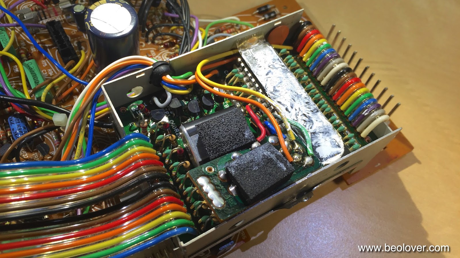
About half of the capacitors were already replaced. I cleaned up a few splashy solder points and then extracted the uProcessor can from the main PCB. then I opened it up:
The later added HEF4013 flipflop board is installed (the small PCB towards the front with a piece of foam on top). Apparently the output of the speed sensor amplifier was not clean enough to give a stable signal to the uProcessor and so they put this flipflop in-between (see sec. 8-4 in the Beogram 8000 Service Manual). Underneath this board the decoupling capacitor of the uProcessor is found. This picture shows the new one that I installed:
After this I buttoned the EMI can up and replaced the capacitor that sits underneath the can before mounting it again on the main PCB:

Here is a picture of the new one:
After that I went on to the 'Settling Circuit' and 'Control for uC' boards that are attached to the main board with one single screw:
After replacing the caps on them I cleaned up their mounting with a second M3 nut that gives the Settling Circuit a bit more space and takes some flex-stress out of the equation and put some decent insulation under the Settling Circuit board with Gorilla tape
which resulted in a straightened up arrangement.

A bit strange this entire design in my opinion...It almost appears that they designed it in several installments and kept adding circuits.

After replacing a few more easily accessible caps on the main board I finally put everything back together and then replaced the 47uF capacitor on the 5V regulator that is mounted to the bottom pan for heat dissipation:

This shows the new one:


Tuesday, November 10, 2015

Beogram 8000: Adjusting Horizontal Parallelism and Glueing the 3D Printed Plastic Tabs to the Carriage

The Beogram 8000 seems to like its new 3D printed plastic tabs that I implemented a few days ago. So I decided to epoxy them in place for long term stability. To be able to clamp them I needed to remove the tonearm carriage from the rail that I could turn it up to apply the clamps:

After applying epoxy to the remaining 'stumps' I clamped the new tabs in place:


After 5 min the epoxy had settled, and I took the opportunity to also adjust the horizontal tonearm parallelism. The adjustment screw can only be accessed from underneath the carriage, so this was the moment:

After adjustment the tonearm was at the same height as the sensor arm:

Lovely!


Friday, November 6, 2015

Beogram 8000: Repair of Broken Off Plastic Tabs on Tonearm Carriage with a 3D Printed Part (II)

Allright! After fixing the broken off tab on the rear of the tonearm carriage of the Beogram 8000 that I am restoring right now, I came up with a similar fix for the broken off tab on the front. This one was a bit easier to access:

I decided to design a 'cap' that would fit on the remaining stump and hold the carriage down on the steep rod on which it travels:

This part was more challenging to print since on one side it had to be very thin to not alter the 'home' position of the carriage, and due to the oval orifice for the rod. Such structures are difficult to print due to th unavoidable gravitational forces that make it difficult to bridge voids with the printer. That is why the part looks a bit 'wobbly'. These pictures show the part installed. Here without steel rod:

And with steel rod in place:

The rod is easily taken out from the plastic receptacles that clamp it in place on either side, i.e. the part can be installed by removing and then inserting the rod into the part, and then clicking the rod back into its receptacles.
I ran the mechanism a few times and it seems to work very nicely...the part does not obstruct anything in the motion path of the carriage. So potentially this is fixed. Like with the tab in the back I had to iterate the part a bit until a good fit was obtained:

I will epoxy the part into place once I am certain it performs well. Without clue it would probably not stay in place during transport. 


Wednesday, November 4, 2015

Beogram 8000: Repair of Broken Off Plastic Tabs on Tonearm Carriage with a 3D Printed Part (I)

I finally got back to the Beogram 8000 that recently arrived from Japan. After fixing the spindle rotary encoder issue, I had to put this project on hold to complete a Beomaster 8000. One of the remaining major restoration tasks was the repair of the broken off plastic tabs that hold the arm carriage to the metal rods on which it rides. They must have broken off during a rough transport experience or a similar stressful moment. Anyway, there was not much choice other than replacing the carriage with one from a donor 8000 or going creative on this issue with a 3D printer. I chose the latter since I usually cannot accept Beograms being parted out.

This picture shows the broken off tab in the back of the carriage:

and the photo below shows the other broken off tab in the front of the carriage. The white stuff is evidence that someone tried to glue the broken off part back into place, but it must have come off again:
The repair of this one will be the topic of my next post. Here is a picture of the second tab in the back that was still in immaculate condition:
It was immediately clear what was missing from the broken off tab: The part that swings underneath the rail rod on which the carriage travels. This keeps the carriage on track even if gravitational forces are briefly suspended during transport etc...

Gluing the broken off parts is futile in such cases. There is no plastic glue that can be strong enough to fix this type of issue. There is just too much torque on the part, while the contact surfaces are really skimpy and no match for the acting forces. So I set out to design a creative solution based on a 3D printed part. This is what I came up with:

The small tab clamps into the gap below the tone arm counter weight and holds the part in place. The bent section of the part goes underneath the rail holding the carriage in place. Here are two pictures of the part installed:

The part clips into place with a solid click and pretty much holds itself in place without the need of glue etc...I will nonetheless glue it once I am confident that it does its job well, to make sure that the Beogram survives its return journey to Japan. It is a pretty interesting process to design such a custom part since it needs to fit an already existing part precisely. This required a number of trial and error iterations until a satisfactory fit and a happy 'click' were achieved. Here is a picture of all the iterations that I printed before I had the one that is shown installed above:
If you look real close, every one is different. A lot of effort, but now the carriage of this Beogram is again held in place safely! At least in the back, the repair of the broken tab in the front will be the topic of my next post.

Thursday, October 8, 2015

Beogram 8000: Not Responding to Keyboard Input - Not Working Rotary Encoder Feedback

A Beogram 8000 hailed from Tokyo in search for some TLC. It was initially purchased from ebay and supposed to be in excellent condition. Once unboxed, however, it turned out that the unit did not work properly. There is already an extensive thread on Beoworld.org about the issues this unit displayed. In a nutshell, when pressing start the arm would run to the end of its range and then be stuck.
Yesterday, I opened the unit up and had a look. I immediately suspected a fault with the rotary encoder that is fitted to the spindle that drives the carriage with the arms. In difference to the earlier 400x models, the 800x employ a more modern positioning concept that is based on detecting the angular motion of the spindle and calculating the carriage position from that. This is a concept that is used in most modern control systems involving motors. The encoder unit is very similar to the ones used in the Beomaster 8000 for the volume and FM frequency wheels.
In the Beogram 8000 the evaluation of the encoder signals is done by the microcontroller, which has two inputs that detect the intensity fluctuations on two sensors. The fluctuations are generated via an aperture wheel that sits between the detectors and the IR emitter. Depending on the phase of the fluctuations on the two detectors relative to each other the system can detect the direction of the motion. The number of intensity oscillations tell the traveled distance. This way, the microcontroller always knows where the needle is. This 'feedback' is used to determine where to set down the arm, when it is time to lift and return home etc...
Therefore, when there is no feedback, the controller does not know anymore where the arm is. The firmware seems to be programmed with simple if...then conditionals that cause action depending on the position. If the position does not change in the mind of the controller (in the case of a non-working encoder system) the arm simply continues to travel until it hits the mechanical stop at the end.

All this suggested to me that I needed to investigate the encoder system to get to the bottom of the issue at hand. Below is the relevant section of the circuit diagram. Since I had similar problems already a couple times with Beomaster 8000s that I restored, I first checked on the functionality of the light detectors and the IR diode (OPE1). In the Beomasters the diodes had failed.

With the multimeter I determined 1.2V at the anode of the diode and this told me that it most likely was o.k. (they usually die by going OC). Then I measured the resistance on the photoresistors. They both showed about 1k when shining a strong LED light into the assembly and about 20-40k when just room light trickled into the setup. This seemed o.k., too. 

So I hooked up my oscilloscope and measured at the P2/6 and P2/4 whether I got pulses when manually turning the spindle. Of course the deck needs to be in PLAY mode or another on state to have things powered up. I had it in PLAY with the carriage belt removed, so the motor simply ran but the spindle did not move. This measurement yielded pulses for both encoder channels. The next step was checking the outputs of the opamps. And there I found a first clue to the problem: IC2 had no pulses at the output, while IC1 gave me nice 5V square pulses.
So I had a look at the PCB, and there it was:

The input of IC2 was short circuited to GND. In the above photo that is the IC pin that is associated with R5. It connects to the adjacent GND pad on the left via a gigantic solder ball. In fact if you look at the entire area it is apparent that someone with very little practice in electronics messed around and did some 'expert work'. Another great example of a 'perfect condition' or 'fully restored' ebay unit....(I hope this guy will smolder for a long time in Vintage Hifi Purgatory when his time comes).

Grounding the IC2 input of course results in a zero output signal since then there is nothing to amplify, and that explained my measurement. I fired up my Hakko desoldering gun and removed the solder from the pads and then resoldered them:

And this did the trick. The unit is working again. I put on my least favorite record (Sam Rivers) that I use for this type of testing, and pressed PLAY. The arm moved to the lead-in groove and lowered. Cueing worked and STOP. Very good!