Featured Post

Beolover SyncDrive: DC Platter Motor Replacement for Beogram 4002 and 4004 (Type 551x and 552x)

Late Beogram 4002 and the 4004 (Types 551x and 552x), which have DC platter motors instead of the earlier synchronous AC motors usually suff...

Showing posts with label o-ring. Show all posts

Sunday, February 11, 2018

Beomaster 6000 (2702) restoration: Motor control and display panel

After spending some time on an urgent repair for another client, I'm back into the Beomaster 6000 quad project. This time I looked at the motor control unit with the display panel. The main items to check are the motor itself and particularly the coupling with the drive shaft, the magnetic clutches (never seen a broken one), the  5 drive belts (O-ring), indicator bands and clips, glass bulbs and the display panel itself. Let's start...


The motor was taken out, cleaned, the flexible coupling renewed and  fresh silicone grease added. A quick test on my bench power supply revealed a very quiet run and about 15mA of current under no load. 
For the new coupling I used quality clear silicone tube with inner diameter of 3mm and outer of 7mm. This is bit thicker than the original black coupling but gives a nice firm fit.


Removing the shaft with the 5 electromagnetic clutches is next. To do this, you only need to remove the 2 small bolts that hold the stop plate.


Then the complete shaft can be taken out for inspection and cleaning. The old belts had been replaced with dial cord as mentioned in an earlier post (click here to go to this post). Be careful: the first clutch comes out completely from the shaft together with a small spring. Easy to loose ! The other clutches can not be removed and are fixed (permanently) to the shaft with a pin.  I like to clean the groves in the clutches where the belt will fit later. These groves can be dirty and result in slipping of the new belts.


When mounting the shaft back into the frame, the new belts need to be added one by one. Make sure you use the correct material for the belts/O-ring (best is EPDM) and the correct size off course. I use 2mm thick and 54mm inner diameter.


Before putting the shaft back in position it is best to fix the motor with the coupling attached first. Then the shaft can be pushed into the mounted coupling. Don't be surprised that the motor is wobbling a bit. This is the way it was designed !


I also replaced a few tantalum capacitors on the PCB at this time.


Moving on to the display panel. This panel is lit with 6 glass bulbs that illuminate a clean plexiglass plate (with some white bands on it) that is fixed on a shiny mirror like frame. 


After cleaning the frame, I was not all that happy. It still showed some "dirty" places where the mirror finish was a bit corroded. I decided to reapply a layer of silver coating. I used "Silver Plater" from Holland Hallmark. This is a liquid that contains real silver and can be used not only to clean silverware but also adds a tiny layer of silver every time you polish/coat it. I applied 3 layers and got a nice results. The reflection you see in the frame is the window in my room!
Not perfect, but  honestly this plate is just used to reflect light and is not visible from the outside. But...shiny does look nice!


The plexiglass also had some very light damage to some of the white painted bands. I used a permanent marker pen to repair the damage.


The purple wheels got a warm bath to clean them and where fitted back on the potentiometers. 


The 5 potentiometers are now fitted back into the frame together with the recapped tone amplifier PCB.  A thin, flat 10 mm spanner is needed to fix them. Make sure that they fit snugly into the provided cut-out in the frame. It's a good idea to move the wheel a bit outside to fit the spanner. After tightening the nut, push the wheel back in place.


The motor control panel with the display is now almost ready. Remains to fix the indicator bands.


The fragile indicator bands are fixed with wedge type clips onto the purple wheel. While it is not that difficult, it takes some practice to fit them correctly. The B&O service manual shows how to put the band around the different wheels. Study this drawing before starting the installation of the band.


The band should not be to tight, not to slack either. I prefer to put the clips at the back of the panel since there is a bit more room. 


I use two fingers to put some tension on the band and put the plastic clip with my other hand.
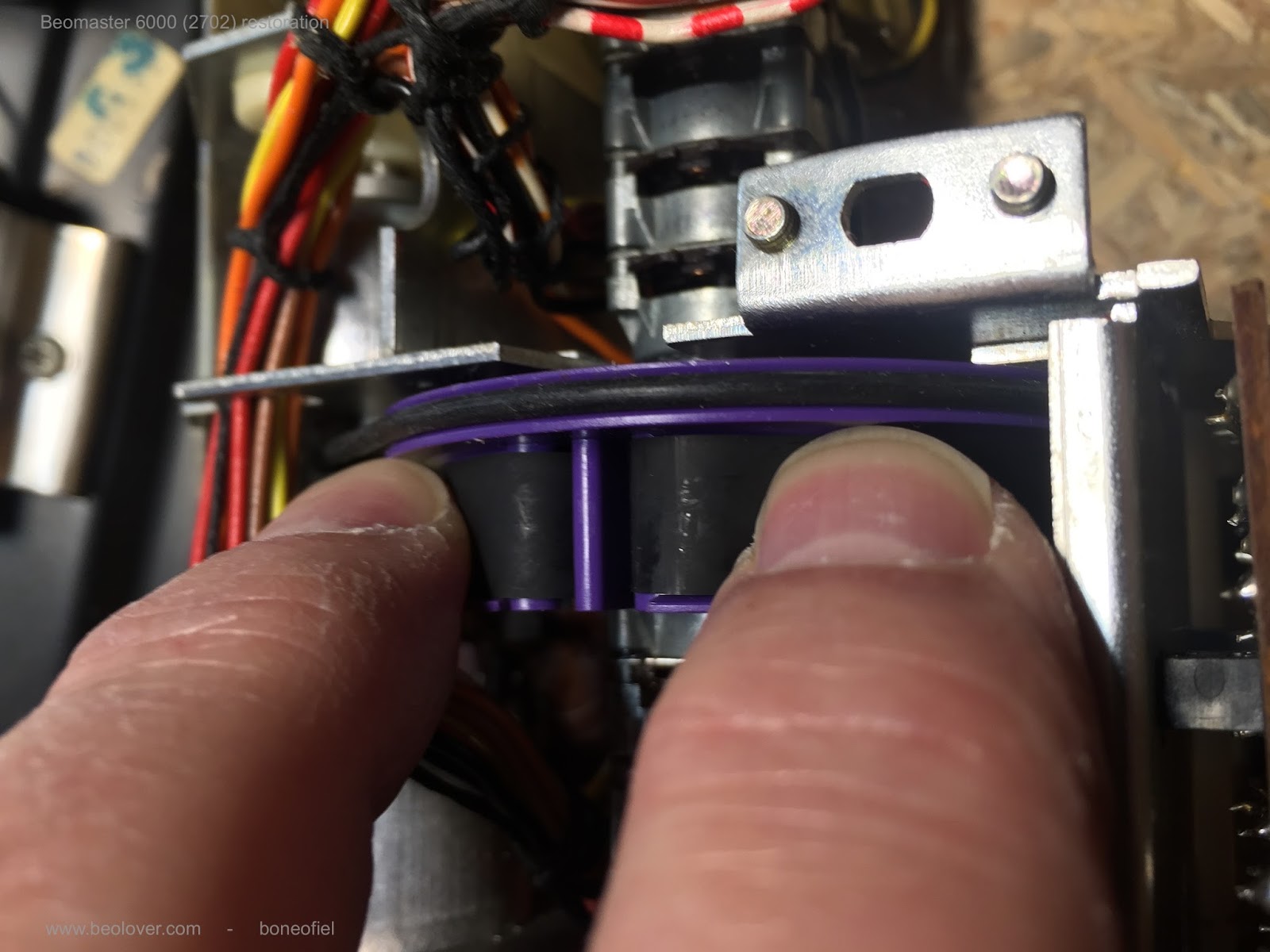


OK. That is done !  There is also a  nice video clip made by Beolover on how to replace the belts (click here)


Friday, April 28, 2017

Beogram 4000: Repair of a Cracked Plexiglass Hood With Laser Cut Patches

The most fragile part of a plexiglass hood of any Beogram is the hinge region. That is where the highest torque is applied to the plexiglass, while it is structurally weakest due to the holes permitting the screws that hold the metal hinge to the hood. The Beogram 4000 that I recently restored had a hood with a large crack through the holes and a broken out piece:
Encouraged by my recent restoration effort on a Beogram 3000 hinge that was broken off I decided to develop a similar fix for the 4000/4002 hoods. Unfortunately, the space one can work with is much less in 400x hoods, since the metal hinge part is bolted to the inside of the hood, i.e. if the plexiglass gets too thick, the metal part does not fit anymore. So my approach here is to use two very thin 20 mil (~0.5 mm) patches that are precision matched to the bolt holes and the hood shape.
But the first step is to try to glue the cracked parts and re-connect the broken out part:
I use Weld-On #4 acrylic glue, which is so liquid that is is drawn into cracks by capillary forces. This is a great feature since one does not have to bend the plexiglass any further to apply it. All one does is squirt a bit on the crack and one can see how it is sucked in. One can then simply press the parts a bit together for ~5 min (play some nice music while you sit there holding the pieces together...;-) and then the next step can be done, which in this case was reattaching the broken out part:
Another 5 min of music listening and then I let it cure for a couple hours. The next step was to attach the laser cut patches. This shows the inner patch:
I used Weld-On #16 for these, since the surface was pretty rough due to the broken out part and previous 'repair' attempts. After curing the patch for ~2 hours (=50% strength of the bond) I did the same for the outer patch:
At this point I let everything cure for 24 hrs to achieve a close to final strength of the bond (~80%). Only after a few days such bonds are fully cured and 100% strength is achieved.
In order to have the metal hinge centered, I also applied an inner patch on the opposite side of the hood. This was a good idea anyway since closer inspection yielded that there already were some minor cracks under development around the screw holes.

Then it was time to bolt the metal hinge in with new stainless steel screws:
The next step was to reattach the aluminum trim to cover the screws. This requires removal of the old glue, which can be done with a razor blade and careful scraping. Take care that the aluminum trim is not bent too much or otherwise damaged. These side parts can break off easily if the bend is flexed too often. I usually use an industrial strength ultra-thin adhesive transfer tape (3M 300LSE) to glue them back on. This allows to generate a very thin and precise adhesive layer, which makes a strong bond. 'Thin' was especially important here to minimize the thickness increase due to the outer patch:
After removal of the tape backing, I pressed the trim on and cleaned some glue splotches from previous repair attempts on the metal surface with Mr. Clean Magic Eraser as good as possible:
This is how this side looks from the front:
It looks pretty good, albeit closer inspection of course will reveal that there is a thin patch underneath. The price for a stabilized hood hinge!

One more thing: Like most Beograms of this vintage, the rubber hood bumpers were broken off:
As usual, I drilled them out with a 2 mm drill bit:
and then glued in snippets of a 2 mm O-ring:
Using a 1 mm template, I cut them to size with a razor blade once the super glue cured:
And here is the end result:
The final step was to polish this hood since it had the usual scratches after about 40 hears in service:
I gave it my usual multi-step polishing procedure that started with 200 grit dry sand paper and then worked it back to a wet 3000 grit level through about 10 sanding steps. I had to be a bit more careful than usual due to the repaired crack. I definitely did not want to break it again...;-). This is how it looks now (still has some black protective tape on the trim):
Time to install it again on this lovely Beogram 4000!


Wednesday, December 2, 2015

Beogram 8000: Replacing the Carriage Belt

Another loose end in the Beogram 8000 that I am readying for shipping I needed to attend to: I earlier noticed that the carriage belt was quite loose, i.e. at the end of its lifetime. On the occasion of my recent effort to replace a cracked BUNA-N volume belt in a Beomaster 6000 I ordered samples of the entire lineup of EPDM 1/16 O-rings at the O-Ring Store with the goal to be ready for future belt replacements of yet unknown diameters. So I thought I probably had the proper EPDM ring for the Beogram 8000 already in stock! And indeed: It turned out that the E70025 (1-3/16" diameter) ring made a good replacement of the original belt. Here are a couple of impressions:

This shows the original belt with rotary encoder sensor cluster removed (just pull the plastic clamp out and carefully pull the board up while making sure that the IR emitter passes through a gap in the encoder wheel), which is necessary to get the belts over the encoder wheel:

And here after installing the new belt:

It is interesting to note that my first attempt with a 1-1/16" belt did not work out. When I checked initially the carriage would move very well with it. However after attempting to play a record, it turned out that the Beogram would have trouble to move the arm to the run-in groove.

What happened was that the firmware in the microcontroller reduces the power on the carriage motor before the touch-down point to get a more precise positioning (and probably also because it just looks more elegant...;-). However this is apparently not done via encoder feedback but rather via a blind  flight power reduction without monitoring the encoder action. This resulted in a very slow movement of the arm do to the unexpected friction caused by the too-tight belt. It would take several seconds from moving swiftly near the position and then via a very slow final movement to the touch-down position. Replacing the ring with the 1-3/16 version cured this issue and now it behaves like with the original ring. All good now under the hood! Playing right now my just arrived 180g reissue of Queen's 'A Day at the Races' - those were the days!...;-)


Wednesday, November 25, 2015

Beomaster 6000 (2253): Volume Belt Installed Four Years Ago All Cracked Up

I am selling a Beomaster 6000 (2253) that I fixed up in 2011. Back then the off-ebay unit had lost its volume belt and so I ordered a new one. Well, I ran it the last two weeks and it worked fine. Then I decided to open it up and have a look, just 'to make sure' before sending it off. And what I found was this:

The belt was all cracked up and only barely still kept it together. A few more months and it would have died for sure. The way this belt looked it is a clear sign that I was sold a BUNA N O-ring seal back then instead of a EPDM transmission belt with round cross-section (I learned about BUNA N the hard way when I did the motor unit of my Beomaster 6000 4-Channel for the second time). I went to my trusted source, the "O-Ring Store" and ordered a bunch of EPDM rings. The BUNA ring measured 1-3/4" diameter, but EPDM is softer. I tried a few sizes and in the end I settled on the 1-1/2 diameter E70029 type which ran without slippage and gave me a taut feeling. Here is an impression:
Beautiful! This should last a while. BTW: The belt is easy to replace. One can simply pull off the string pulley from the volume potentiometer, place the ring over it and stick it back on the shaft. Carefully done, this avoids having to mess with the string driven volume indicator.


Monday, September 22, 2014

Beomaster 6000 4-Channel: Positioning the Indicator Bands

I finally had some time to continue the LED-ification project of my Beomaster 6000 4-Channel (several of the lightbulb fixtures had broken out tab-receptacles, and I did not want to use tape to fix them in place, so I decided to do it with LEDs)

I made some major progress on this today, and it seems everything is finally working. More about that after I do some more testing of this set-up.

I was confident enough to re-install (for the 4th time, I think...patience is a great asset with the Beomaster 6000...;-)) the indicator bands of the motor unit. I realized that I previously adjusted them slightly wrong in their position. So I wanted to share here how to do it right: 

The small white dots in the indicator panel are meant to adjust the bands relative to the potentiometer position. This is how I aligned them this time before pushing in the clips (see here for details on the entire procedure and a video):


That's it for today...

Thursday, May 15, 2014

Beomaster 6000 4-Channel: Rebuilding the Motor Unit

Oh well, another setback!!... While messing with the output amplifier and doing the tuner dial string etc...I had to witness the degradation of the Buna N O-rings that I installed a month back into the Beomaster 6000's motor unit. I could literally see how cracks in the Buna N rings developed that increased in depth every day in a noticeable way. I think in another month the rings would have broken and fallen off by themselves. Here is a picture of the damage:


Pretty uncool! Anyway, this meant I needed to redo everything, and I already had the indicator bands installed.
I studied up on O-rings and the materials they are made from. It turns out that the best material for 'drive belt' uses under tension is EPDM rubber (ethylene propylene diene monomer rubber). I found the "Parker O-ring Handbook", and guess what, it has a chapter on "Drive Belt Applications" (section 3.17). There it suggests material "E0751-65" as ideal for drive belt applications. A bit of internet sleuthing then yielded that this is EPDM...unfortunately it is very difficult to buy Parker products as a private person...it seems they have a distribution system that is loth of modern purchasing methods, i.e they want you to go to a local handyman location to pick up the O-ring...crazy! So I went to the O-ring store, and ordered six of their E70032 model, which is a 1-7/8 inner diameter 1/8" thick ring made from EPDM. I also went through a learning curve with regard to the inner diameter - the original rings measured 2" diameter, and I installed the E70033 model first, which has 2" diameter, only to learn that two of the potentiometer drives slipped with these due to a bit higher resistance in these pots...so I had to do it a 3rd time with the 32 size...live and learn!

Anyway, I was able to finally complete the repair, and I made another video about the process. This video shows the entire process: Removing the indicator bands, putting in the new rings, and putting the bands back in. There is also a demo of the rebuilt unit in action at the end. You can find it on YouTube:


********Please, note that the video does not make clear how to properly position the indicator bands relative to the potentiometers. See this post for details.**************************************

Another interesting issue about this repair procedure was the brittleness of the V-shaped plastic clips that hold the indicator bands to the purple drive pulleys on the potentiometers. The original clips immediately broke when I tried to squeeze them a bit when reinstalling the bands:


So I took measurements of one of the still intact ones, and made a model in Autodesk Inventor. Then I exported the finished model as an STL file and printed it on a Makerbot II in yellow PLA (I thought the yellow would work well with the purple drive wheels, adding to the colorful interior of the Beomaster 6000....;-).
Here are the new clips:


Pretty cool! But I had to manually Dremel the grates off at the side that connected to the plate of the printer to prevent damage to the indicator bands when sliding the clips in.

This worked very well. They can be installed by squeezing them together with needle nose pliers and pushing them in from the top while bunching the band ends together into the 'crack' (sounds more complicated than it is - watch the video posted above - it shows this process in detail).


In a second step, the clips are pushed into the wheels until they seat against the wall:


And that is pretty much it. I really like the yellow-on-purple theme...;-). Watch the video for a demonstration of the rebuilt unit and the clutch mechanism.