Beolover provides professional maintenance and restoration services for vintage Bang&Olufsen stereos. We give one year warranty on parts and labor. All parts featured on the blog are available at our Store for DIY. Please, send an email for inquiries. Enjoy the blog!
The Beogram 4000 from Australia that I am restoring right now kept on giving! After I fixed the tonearm wiring to get both stereo channels working further tests revealed that it would not recognize the absence of a record and eagerly put down the arm onto an empty platter. Luckily I had already adjusted the arm lowering limit and so nothing happened to my MMC20 EN cartridge.
Ignoring the absence of a record is a telltale sign for a dead photocell in the sensor arm. The circuitry recognizes a dead sensor arm bulb and shuts down arm lowering if this is detected. However, a damaged photocell is not recognized. It simply simulates a black surface on the platter, and so the arm lowers.
I pulled out the sensor compartment and closer inspection revealed that one of the two electrodes on the photocell had disconnected. It looked like this:
This photo is from an earlier post about this type of issue, where the photocell of a Beogram 4002 had come apart. This earlier post reports about my initial development efforts aiming for a suitable replacement of the original photocell.
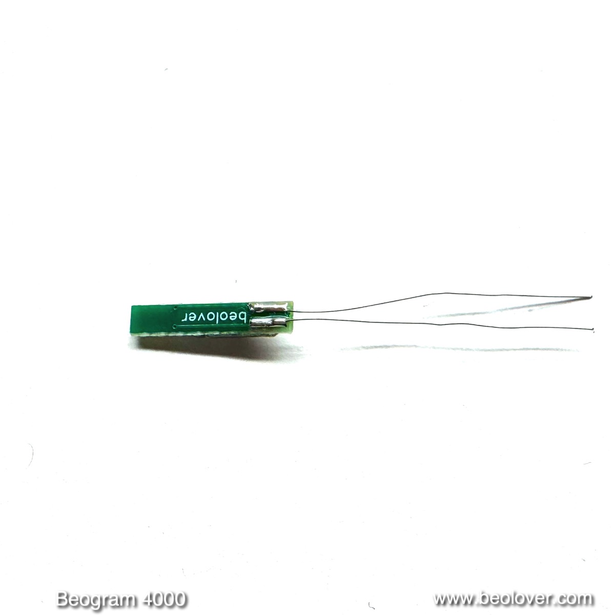
At the front end (left) there are three photodiodes in parallel (to ensure sufficient current generation). On the back end (right) a 3D printed alignment piece is installed that helps keeping the cell properly oriented and in its proper spot relative to the lens in the sensor arm compartment.
This shows the backside with the two contact leads:
This is a real photocell like the original. It puts out ~0.45V photovoltage when exposed to sufficient light:
This means that unlike with other photocell replacement schemes no circuit modification is necessary. This is a direct drop-in part that replaces the original photocell (B&O part 8760002)
Installation is simple: Just stick the leads into the holes in the small circuit board attached to the sensor arm compartment (it is a good idea to use a solder sucker to remove the solder from the solder pads on the backside of this board to ensure the holes are open after unsoldering the original cell):
Then insert the photocell into the small compartment where the original cell was located and align the small protrusion on the alignment piece with the hollow rivet that holds the PCB to the plastic part:
Then press the back end down until the frontend with the photocells hits the roof of the compartment:
Then the leads can be soldered to the pads on the underside of the PCB:
This shows the underside with the red and blue photo cell leads attached:
I tested the new cell with my oscilloscope, which was connected to the collector of the sensor transistor 1TR14 whose collector DC bias was adjusted to be 1.8V:
The photocell yielded a strong 2.5V amplitude signal over the rotating platter. More than spec. So all is good again in the record detection department.
When I encountered the above, I first wanted to replicate the phototransistor solution, but then I remembered that a photovoltaic cell (aka 'solar cell') is in its simplest form just a pn-diode. Such diodes can actively generate a current when exposed to light if a load is connected. The photocell in the sensor arm is basically such a diode. It generates a light induced AC current (as the platter ribs pass through underneath it) that is fed via a capacitor (to keep DC components from background light out) into the base of a transistor (TR3 in the 5513 circuit) that amplifies this current, which is ultimately used to drive a transistor that disables the arm lowering mechanism.
So the thought occurred to me that one could potentially use a photodiode and simply replace the photocell without further circuit modification. Phototransistors do not generate significant currents by themselves due to their symmetrical npn or pnp junction configurations, and therefore they need added circuitry in this case.
I ordered a few photodiodes for visible light detection that had a suitable form factor for this project. Indeed, most of them showed various voltages when exposed to light. I ended up using a PIN (p-type/insulator/n-type junction) silicon cell in a 0805 SMD package. I soldered two 32 gauge wires to it for testing:
It yielded 0.45V into the 10 MOhm of my multimeter when exposed to my fairly strong bench LED lights:
I installed it using the original insulator tubes:
And I got a decent response at the collector of TR3 when I spun the platter under it and pushed the extracted sensor compartment a couple mm towards the platter. But the signal was still too small and had an inverted look:
I concluded that a single diode did not have enough current capability under the given light situation for driving TR3 properly, so I decided to replace it with three units connected in parallel for my next test. I also reversed the polarity:
I installed the assembly. This time I did not use the insulator tubes, but instead supported the leads by a small piece of suitably thick cardboard. I fixated the leads to it with a dab of epoxy to hold everything in the correct position:
And I measured a nice 5.72V amplitude at the collector at TR3 with the sensor compartment properly inserted into the arm!:
I also tested it with and without record on the platter and the arm did not stop or lower on the empty platter, as it should. All good again in the sensor arm department! This Beogram is ready to be sent back to its owner in California!
In the last post comments I mentioned learning something new every time I work on these Beogram turntables. This is certainly one of those cases. I installed the Beolover LED module in the fixed arm sensor assembly that I had swapped with a spare Beogram 4004 turntable. That sensor measured exactly as I wanted using the original incandescent lamp so this new LED light source should work just as well. To my surprise the LED light source produced a weaker sensor signal than the incandescent lamp. The signal was better than with the original sensor assembly but it still wasn't at the level I need it to be in order to continue with this restoration.
The peak-to-peak voltage target is 6 V and the above signal is still short.
Even though the LED light source looks brighter than the incandescent bulb there are other factors involved like the angle of the light on the spot that the sensor is focused on and the wavelength of the light. I discussed this with Beolover and determined that I needed to adjust the LED position on the Beolover light source.
Here is the Beolover LED module. The blue arrow shows the direction I am moving the surface mounted LED. How convenient that Beolover designed the solder pads for mounting the LED so that its position can be adjusted.
That was all it needed. The new position of the light source provides the necessary light stimulus to the sensor where it can now produce a healthy 6 V peak-to-peak record detection signal.
I am now confident in this circuit so I can continue on to the Beogram 4004's platter height adjustments.
The Beogram 8000 seems to like its new 3D printed plastic tabs that I implemented a few days ago. So I decided to epoxy them in place for long term stability. To be able to clamp them I needed to remove the tonearm carriage from the rail that I could turn it up to apply the clamps:
After applying epoxy to the remaining 'stumps' I clamped the new tabs in place:
After 5 min the epoxy had settled, and I took the opportunity to also adjust the horizontal tonearm parallelism. The adjustment screw can only be accessed from underneath the carriage, so this was the moment:
After adjustment the tonearm was at the same height as the sensor arm:
I decided to design a 'cap' that would fit on the remaining stump and hold the carriage down on the steep rod on which it travels:
This part was more challenging to print since on one side it had to be very thin to not alter the 'home' position of the carriage, and due to the oval orifice for the rod. Such structures are difficult to print due to th unavoidable gravitational forces that make it difficult to bridge voids with the printer. That is why the part looks a bit 'wobbly'. These pictures show the part installed. Here without steel rod:
And with steel rod in place:
The rod is easily taken out from the plastic receptacles that clamp it in place on either side, i.e. the part can be installed by removing and then inserting the rod into the part, and then clicking the rod back into its receptacles.
I ran the mechanism a few times and it seems to work very nicely...the part does not obstruct anything in the motion path of the carriage. So potentially this is fixed. Like with the tab in the back I had to iterate the part a bit until a good fit was obtained:
I will epoxy the part into place once I am certain it performs well. Without clue it would probably not stay in place during transport.
I finally got back to the Beogram 8000 that recently arrived from Japan. After fixing the spindle rotary encoder issue, I had to put this project on hold to complete a Beomaster 8000. One of the remaining major restoration tasks was the repair of the broken off plastic tabs that hold the arm carriage to the metal rods on which it rides. They must have broken off during a rough transport experience or a similar stressful moment. Anyway, there was not much choice other than replacing the carriage with one from a donor 8000 or going creative on this issue with a 3D printer. I chose the latter since I usually cannot accept Beograms being parted out.
This picture shows the broken off tab in the back of the carriage:
and the photo below shows the other broken off tab in the front of the carriage. The white stuff is evidence that someone tried to glue the broken off part back into place, but it must have come off again:
The repair of this one will be the topic of my next post. Here is a picture of the second tab in the back that was still in immaculate condition:
It was immediately clear what was missing from the broken off tab: The part that swings underneath the rail rod on which the carriage travels. This keeps the carriage on track even if gravitational forces are briefly suspended during transport etc...
Gluing the broken off parts is futile in such cases. There is no plastic glue that can be strong enough to fix this type of issue. There is just too much torque on the part, while the contact surfaces are really skimpy and no match for the acting forces. So I set out to design a creative solution based on a 3D printed part. This is what I came up with:
The small tab clamps into the gap below the tone arm counter weight and holds the part in place. The bent section of the part goes underneath the rail holding the carriage in place. Here are two pictures of the part installed:
The part clips into place with a solid click and pretty much holds itself in place without the need of glue etc...I will nonetheless glue it once I am confident that it does its job well, to make sure that the Beogram survives its return journey to Japan. It is a pretty interesting process to design such a custom part since it needs to fit an already existing part precisely. This required a number of trial and error iterations until a satisfactory fit and a happy 'click' were achieved. Here is a picture of all the iterations that I printed before I had the one that is shown installed above:
If you look real close, every one is different. A lot of effort, but now the carriage of this Beogram is again held in place safely! At least in the back, the repair of the broken tab in the front will be the topic of my next post.
It turned out that the linkage that connects solenoid mechanism and tonearm was seized in the Beogram 4000 that I obtained from the UK. This meant I had to take the sensor arm assembly out to extract the linkage that I could relubricate it. It turned out that the pin on which it usually rotates had seized in the linkage and that the pin was liberated from its pressfit socket in the sensor arm base. I made a video that explains the issue and shows how to repair it:
I just received another Beogram 4000. This time from the UK. The unit is in decent condition, at least it has the MMC cartridge mount intact and the sensor arm insert is still there. The cueing/tonearm lift control panel came loose during transport. A great idea to tape them down. Luckily, the seller had the deck covered with a heavy duty plastic foil under the hood, so nothing bad happened. It will be straight forward to re-attach the panel.
Inside it seems everything is present:
But of course, like most units of this age it passed through some less-inclined hands and suffered a bit. I am not sure what attracts people to cutting off power cords, but this one, like the one I just obtained locally, had its power cord severed. So I bought a power plug and attached it to the cord:
Then it was time to plug it in. The first thing I usually do with a Beogram of unknown provenance, I measure if the voltage rails are present. At C1 one can measure the rectifier output for the 6V rail that drives the control system. It should be somewhere around 12V:
And on C2 one can measure the regulated 6V rail:
This looked pretty reasonable, so I went on to the 24V rail that is responsible for the power side of things. First I went for the rectifier output at C3:
And then for the regulated 24V rail at C4:
This seemed within spec, so these capacitors seem to have some remaining life left in them. I will exchange them anyway, but this was good enough for an initial turn-on of the deck.
I pressed the start button. Happy moment: The strobe lamp still works:
The carriage was also set in motion (good!), but then at the point where the tone arm should have been lowered into the lead-in groove of a 30 cm vinyl, a strange phenomenon occurred: The solenoid emitted a loud noise and its plunger oscillated rapidly. A 2 min video is more than a 1000 words, so I made one! Here it is. It demos the issue and shows how I repaired it.
Essentially, all it took to fix this was to reattach the lead that connects the emitter of TR4 to the current limiting resistor that is on PCB #7:
Let's see what else this Beogram has in storage for the Beolover!