Featured Post

Beolover SyncDrive: DC Platter Motor Replacement for Beogram 4002 and 4004 (Type 551x and 552x)

Late Beogram 4002 and the 4004 (Types 551x and 552x), which have DC platter motors instead of the earlier synchronous AC motors usually suff...

Showing posts with label tangential arm assembly. Show all posts

Saturday, June 25, 2022

Beogram 4004 Type 5526: Restoration work - Part 4

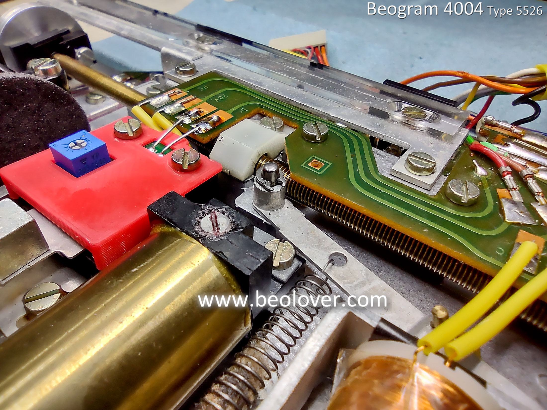
I wrapped up the floating chassis component tasks by reassembling the tangential arm assembly.
During the reassembly I performed some key lubrication tasks like new PMX - 200 silicone fluid in the lowering damper and a mixture of Rocol MTS 2000 grease with Mobile NUTO H32 oil.  
More modern lubricants are available today but I have plenty of the original lubricants called for in the Beogram 4004 service manual so I like to use those.

I applied some Molykote DX paste (grease) to the two tangential arm assembly rails first.


Then I opened the tonearm lowering damper to clean it and apply some PMX - 200 silicone fluid.


Next I mixed some Nuto H32 oil with Rocol MTS grease for the lubrication mixture on the tangential arm assembly spindle.


The Beogram 4004 tangential arm assembly components can now be reassembled on the floating chassis.


At this point I like to check the tonearm tracking force calibration.
The parts are easy to get to so it is a good place to calibrate the tracking force.


The Beogram 4004 floating chassis (and components) are ready to go into the base cabinet again.


Sunday, June 19, 2022

Beogram 4004 Type 5526: Starting in on the restoration work - Part 1

Since the last post I have jumped into the Beogram 4004 restoration tasks.
I am going to show the before and after pictures of the PCB 1 and PCB 8 capacitor replacements but I am also going to show a few other tasks that I performed along the way.

Before tackling the PCB 1 and PCB 8 part replacements I wanted to get the problem of the End Switch (ES) and Switch On/Off (SO) switches resolved.

The previous post showed the broken ES switch.  I decided to replace both the ES and SO switches with a good set from a spare Beogram 4002 Type 5513 unit.

Here are a couple of before photos -


Here are the two replacement switches installed -


While I had the Beogram 4004 floating chassis components in front of me I continued by disassembling components I am going to replace or restore.

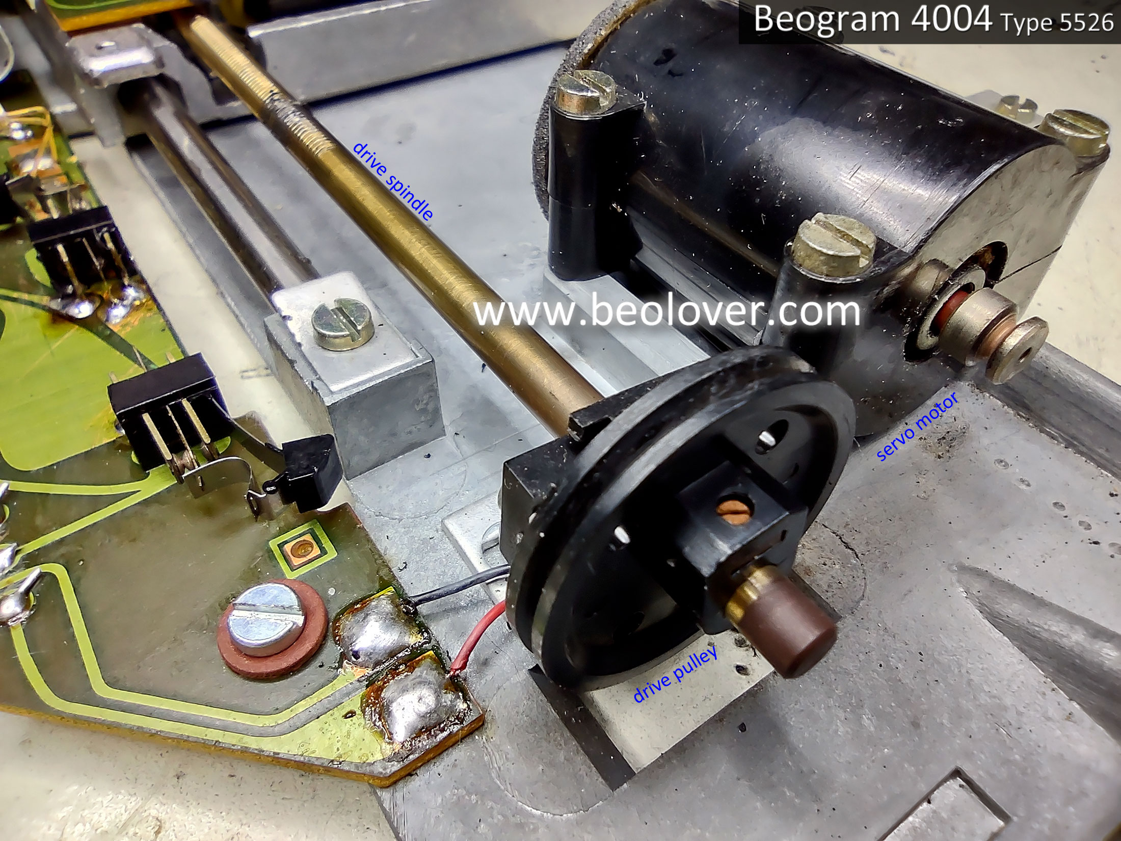
Next, I removed the servo motor and the tangential drive spindle/pulley assembly.


Here is the servo motor opened up.
The foam padding is still intact but pretty brittle. It will eventually completely dry out and start breaking into pieces so I will replace it with new vibration damping material.


I cleaned the spindle with a brush and some alcohol. 
I removed the original, plastic pulley from the spindle and installed an aluminum pulley.


Next, I removed the original tracking sensor lamp assembly to prepare for the installation of the replacement Beolover Beogram 400x tracking sensor lamp assembly.


With the tangential drive spindle removed the tangential arm assembly can easily be slid up and down the two guide rails.  This is a good time to clean them before applying new grease.


That is all I am going to do on the floating chassis components for now.
It is time to move on to the work on PCB 1 and PCB 8.
Once those are complete I will return to the floating chassis to install the new Beolover tracking sensor lamp assembly along with replacing the fixed arm, record detection lamp (also a Beolover lamp assembly).

Here is the before photo of the Beogram 4004 Type 5526 PCB 1, the main turntable electronic control circuits.


Here is the PCB 1 after photo...after the capacitor replacement has been done, a new platter speed selection relay has been installed, new trimmers for the platter speed control, new trimmer for the position sensor calibration (1R88), new 1TR3 transistor for the record detection circuit and a corresponding 2MΩ trimmer for calibrating it (in place of the original 1MΩ, 1R26).


Note: As we normally do, the 2MΩ, 1R26 trimmer is installed temporarily on the trace side of PCB 1 so it is accessible when it is initially set (to calibrate 1TR3).  Once the calibration is done, the 1R26 trimmer will be moved to the component side of PCB 1.  You can also see that a WIMA 4.7uF capacitor has been located on the trace side of PCB 1.  That component will stay on the trace side as I don't want any possibility of it physically interfering with the floating chassis mount that sits below PBC 1.
Regarding transistor 1TR3...the original transistor measured with an Hfe below 500 so I installed a new transistor that has an Hfe of above 500.  Together with the 1R26, 2MΩ trimmer there should be no problem adjusting the record detection signal per the service manual.

I also worked on the Beogram 4004 Output circuit board (PCB 8).
The Beogram 4004 Output circuit board has a lot more components than a Beogram 4002 from the same time period (i.e. a Beogram 4002 Type 5523).  The reason for that is the Beogram 4004 has a remote control circuit that ties in with a Beomaster 2400 receiver.  

Here is the before photo of the PCB 8 board.


Here is the after photo.


Things to note on the updated board are the replacement of the muting relay and the addition of a grounding selection switch.

We install this type of switch on all of our Beogram 400x turntable restorations to provide an easily accessible control over the way the signal ground and chassis ground are configured inside the Beogram for the phono cable.  Some phono amplifiers need signal ground and chassis ground tied together or else there is hum on the phono signal.  Other phono amplifiers do not.  The switch makes both options available for the owner.

The project is getting close to actual record play now.

In the next post I will install the new Beolover Fixed Arm Lamp Assembly,  the Beolover Tracking Sensor Lamp Assembly, lubricate the tangential arm assembly and perform the service manual tonearm adjustments.

Friday, June 5, 2020

Beogram 4002 Type 5513: Reinstalling the Floating Chassis Components

I have all of the restoration parts I need for this Beogram 4002 (Type 5513) turntable now.

It is time to reinstall the floating chassis with the tangential arm assembly back into the Beogram 4002 cabinet.

First the Beolover replacement suspension lock bushings are installed on the floating chassis.


Then the suspension locks are placed in the cabinet base.


The floating chassis is placed over the locking bolts and the rest of the locking mechanism is installed.


With the floating chassis and its components reinstalled I can finish the wiring to the new reservoir capacitor assembly.


...and install the Beolover restored platter motor.


This Beogram can now be moved to the test bench where I will install the circuit boards and control panel. Then I can start going through voltage checks and service manual adjustments.

Monday, June 1, 2020

Beogram 4002 Type 5513: Going over the chassis and mechanical parts

The two circuit boards that require recapping and other restoration work are done. Now it is time to dive into the Beogram 4002 cabinet and look in more detail at the electro-mechanical parts.

I like to remove the floating chassis to work on it. I plan on taking a lot of the tangential arm assembly apart anyway so removing the floating chassis makes that work easier for me.


As it turns out it also reveals some hidden problems.

I originally thought the three chassis lock down bushings were still good. They appeared to be intact but opening up the lock down mechanism proved otherwise.


First sign that the bushings were not in as good shape as I thought.


The more I handled the old bushings the more they fell apart.


Fortunately Beolover makes a set of replacement bushings so I quickly ordered a set from him.

Next up, a look at the condition of the tangential arm drive assembly.
I opened up the ball socket that houses the nylon nut the drive spindle rotates in to move the tangential arm assembly forward and back.

The old grease had started to harden up on this Beogram. The service manual says it should be an oily consistency. I will clean all of that off and reapply a new coat of lubricant.


Here are the tangential drive components removed and cleaned up.


When I reassemble the drive components I will also replace the original plastic pulley with a new, aluminum one I got from Beolover.


The above photo also shows that I had replaced the arm position sensor lamp with a new LED light source.

Here is the original LED.  They typically go out by now so I removed it and tested it. The LED was indeed dead.


I used an amber colored LED to replace it.


I will fine tune the lamp position as related to the angle its light hits the arm position sensor. There is a service manual adjustment for the expected sensor voltage when the lamp source is on.

I removed the original lamp source for the tangential tracking sensor as I will be replacing that light source with Beolover's LED replacement module.

With the light source module removed I can see that the metal tracking sensor shutter (that is attached to the tonearm base) looks like it is positioned correctly.

It mustn't rub on the black plastic housing of the tracking sensor but should be close to it. The service manual calls for a 1 mm gap.


The rest of the components that make up the tangential arm assembly are clean and move freely. I can see a few places where service manual adjustments will have to be performed but the arm lift and lowering  mechanisms move easily.

Other than a couple drops of synthetic oil on pivot points I don't see anything else that needs to be taken apart on the arm assembly.


I lubricated the tangential arm drive spindle with a new mixture of Rocol 1000 and Mobile NUTO H32 as called out in the service manual. There are other options if you don't have access to those products. I have collected some though so I like using what B&O originally used.


For the two shaft tie-rods that the tangential arm assembly rides on I applied a thin coat of white, DX Molykote paste.


The floating chassis is reassembled.  I just need to install the Beolover replacement bushings for the chassis locks then put everything back together in the Beogram cabinet base.