Featured Post

Beolover SyncDrive: DC Platter Motor Replacement for Beogram 4002 and 4004 (Type 551x and 552x)

Late Beogram 4002 and the 4004 (Types 551x and 552x), which have DC platter motors instead of the earlier synchronous AC motors usually suff...

Showing posts with label tracking sensor. Show all posts

Wednesday, October 30, 2024

Beogram 4002 (5513): Another Beogram From Houston - Mechanical Work

The restoration work on this Beogram 4002 (Type 5513) begins with the various mechanical restoration tasks.

Those include cleaning out the debris from the cabinet base and some disassembly of the floating chassis components for cleaning and lubricating.

The arm lowering & raising lever is attached to the fixed arm.  The pivot for that lever can occasionally get gunked up so we typically remove it for a clean and lubrication.


The arm lowering damper is also cleaned.  The rubber washer on the end of the plunger gets replaced with a new washer and the metal part of the plunger is lightly lubricated with a silicone lubricant.


The tangential arm spindle parts are removed for cleaning and lubrication.
I don't immediately re-install the spindle however as I find it easier to make a few Service Manual mechanical adjustments with the tangential arm assembly free to slide back and forth.


Before making any Service Manual mechanical adjustments I like to move the four set screws that sit underneath the two metal rails the tangential arm assembly rides on.

These set screws are for adjusting the height of the rails but the slotted end to make the adjustment with sits underneath the floating chassis.  I remove them and re-insert them from the top.  This allows any change in their height to be made from the top side of the floating chassis without having to remove the floating chassis from the cabinet.

Here is a photo of one of the re-inserted set screws.


That gives a little peace of mind in case some change in the tangential arm assembly height is necessary.  Normally it shouldn't be but the set screws allow about 3 mm of height adjustment.

Next I reassembly the tangential arm assembly and go through the adjustments to make sure the arms are perpendicular to the back rail, parallel to each other and have the proper distance to the platter.

The Service Manual says the distance between the Fixed arm and Tonearm is 7.7 mm.


The top of the Fixed arm to the top of the platter (metal) surface has to be 23 mm.


After that is set the tops of the two arms (Fixed and Tonearm) should be even.  If they are not, the Tonearm height can be adjusted. 


With a phono cartridge mounted I check that the Tonearm and cartridge vertical alignment (azimuth) is good.


I set the Tonearm lowering limit so the stylus of the cartridge is about 0.5 mm above the lower platter rib.


I calibrated the tracking force of the Tonearm/Cartridge so that it measures 1.0 gram with the tracking force knob set at 1 gram. 


After that calibration I set the tracking force knob to 1.2 grams.

Before installing the Beolover Tracking Sensor Lamp component to the Beogram 4002 Tracking Sensor Assembly, I checked and adjusted the metal aperture so it is 1 mm above the Tracking Sensor.


The Beolover Tracking Sensor Lamp was then installed followed by the Tangential Arm Assembly spindle parts.  The plastic pulley on the spindle was replaced with an aluminum pulley.
When the spindle was installed I lubricated it with a mixture of grease and oil.  Not too thick and not too thin.


The floating chassis components can now be re-installed in the Beogram 4002 cabinet base where the suspension will be adjusted so the top of the platter is even with the cabinet aluminum deck.

Along with that, the platter motor and reservoir capacitor assemblies will be installed.


I'm pleased with the mechanical adjustments so far.  The re-installed floating chassis aligns good with the aluminum deck plate so it is on to the rest of the electronic restoration tasks.

Those include the restoration work on the main PCB, the output (audio muting) PCB, the LED lamps for the speed indicators, the arm detector lamp (in the Fixed arm) and the contact cleaning on the Beogram control panel buttons...Plus all of the related adjustments.

Monday, June 5, 2023

Beogram 8000 Type 5513: Tomball Texas Project Final Adjustments and First Record Play

The Beogram 8000 restoration project from Tomball, Texas is playing records again.

To get to this point I had to perform some remaining adjustments.

First was the forward/reverse scanning LDR adjustments.  Those are for the tonearm forward and reverse buttons on the control panel.  The Beogram 8000 uses a couple of LDR devices (resistors that change value when light hits them) and a rocker spring that is an aperture for the light source to strike the LDR.
The steady state voltage level of the two LDR devices (forward and reverse) should be around 620 millivolts (DC). I like to set them at around 650 mVdc. They are dialed in by an adjustment screw that affects the amount of light to the sensor.  

The adjustment screws are a rather coarse adjustment and is why I installed the little test connector to make tweaking the setting easier (especially after the Beogram 8000 is fully reassembled in its cabinet).

Here are the forward and reverse, steady-state measurements for the LDR devices.


I also measured the +5 VDC, +15 VDC and -15 VDC power supplies again.
I measured the +5 VDC at the filter capacitor inside the PCB 2 assembly that supplies power to the microcomputer (uC).


I checked the +15 VDC voltage going into the regulator and coming out of the regulator.


I measured the -15 VDC off the 1TR19 collector where that voltage regulation output is located.


From there I moved to making some measurements on the oscilloscope of the speed sensor, the two position sensors and the record detection sensor.

For the speed sensor I measured the raw signal coming off the sensor assembly, then at uC (2UI1-40) after the signal has been filtered.

Here is the measurement point for the raw signal from the sensor assembly (P4 pin 7).


Here is the measurement point on 2IC1-40 (uC).


...and here is what the oscilloscope shows.


Next are the measurements for the two position sensor signals and the record detector signal.
I made those measurements with the tangential arm assembly moving forward and in reverse.

Here are the measurement points.


...and the oscilloscope measurements.


The supply voltages and sensors all looked good so I moved to the final two adjustments on this Beogram 8000.

The first adjustment was to check the phono cartridge tracking force and adjust it if necessary.
The second adjustment was to set the sensitivity of the tangential tracking sensor.

For both of these adjustments I need the Beogram 8000 where I can operate it but I don't want the platter to rotate.  With a belt driven turntable it is just a matter of removing the belt.
On the Beogram 8000 it means disconnecting the P4 connector on PCB 1.  

Just to be safe, disconnect and connect the cables with the Beogram unplugged from the wall.


The tracking force and tracking sensitivity are both adjusted on the tonearm assembly.


The tracking force for the phono cartridge is always available for the owner to set using the small adjustment slider under the tracking force scale (along the side of the tonearm).
What I do during the service manual checks is calibrate the tracking weight so it is as close to 1 gram as I can get it with the slider set to "1" on the scale.

To do that I use a digital scale and adjust the tracking force counter-weight position as necessary to get 1 gram on the measurement.

Note: I make the tracking force measurement with the platter turned upside-down because it is flat enough for the measurement scale to rest on.


On the tracking sensitivity adjustment the procedure is to place a test record on the platter, then advance the tonearm over a test track (usually in the middle of the record) and set the arm down.
I also set the arm down (with a phono cartridge attached) before that and make sure that the tracking sensitivity isn't too sensitive where the arm starts moving forward by itself.

The arm should lower straight down and the phono stylus sits in the record groove with no forward advancement of the servo motor (that drives the tonearm assembly).

Next, the platter is manually rotated and the servo motor is observed for movement.
The servo motor should advance the arm within one or two revolutions of the platter to begin with, then every platter revolution after.

Should the tracking sensitivity require adjustment, there is a small adjustment screw on the side of the tangential arm assembly...shown here.


That completes the Beogram 8000 adjustments.  Now it was time to actually play a record.

I will do more complete record play testing later, when the Beogram 8000 is fully assembled.
At this point however, I like testing record play with my Workshop Beomaster 8000.
Besides being anxious to listen to a record, now is a good time to check the record play functions.
If there was a problem, the Beogram 8000 is already open for trouble-shooting.

I like testing with a Beomaster 8000 because the two components are integrated with their controls.
Pressing Play on the Beogram 8000 will cause the Beomaster 8000 to turn on and switch to the phono (PH) source.  Pressing PH on the Beomaster 8000 will cause the Beogram 8000 to start playing a record.

Note: I keep my Workshop Beomaster 8000 opened up for servicing at all times so I can use it for Beomaster 8000 board testing. Just like I keep my Workshop Beogram 8000 opened up.

The first record play test performed perfectly so I just relaxed and finished the day listening to some vinyl.


Monday, June 20, 2022

Beogram 4004 Type 5526: Restoration work - Part 2

I continued the main restoration tasks on this Beogram 4004 today by performing the following tasks -

Replacing the Fixed Arm Record Detection Sensor Lamp with the new version of the Beolover LED Record Detection Sensor Lamp.

Replacing the Tracking Sensor Lamp with the Beolover LED Tracking Sensor Lamp.

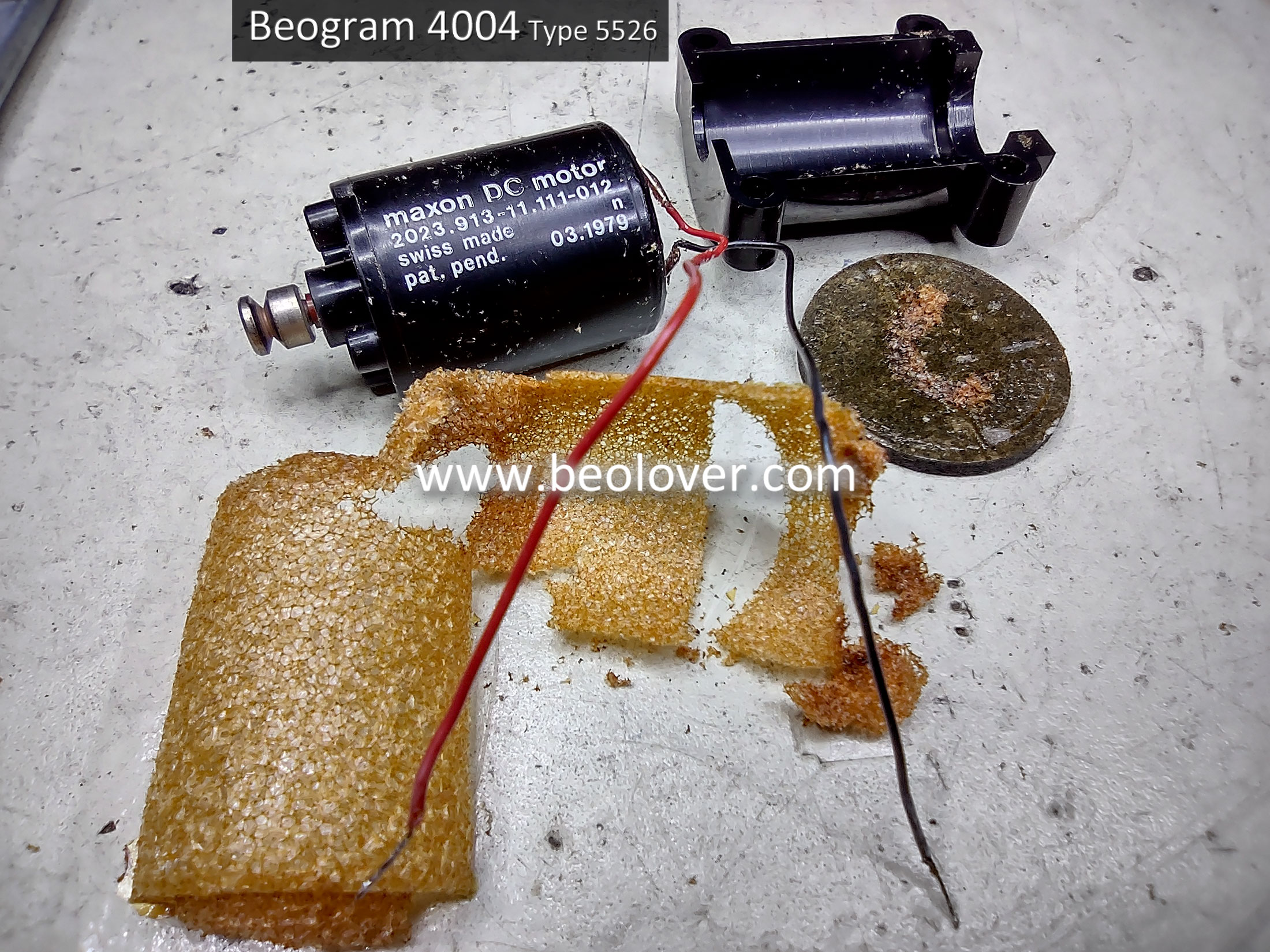
Replacing the old Servo Motor damping material with new neoprene closed-cell foam material.

The following series of photos show the steps in replacing the Fixed Arm Record Detection Sensor Lamp.

The lamp and sensor assembly pull out from the front end of the Fixed Arm.


Note that the new Beolover LED sensor lamp leads are bent up a little before the solder connection.
The reason for that is to ensure the lead doesn't short to the mounting rivet of the small board in the Fixed Arm.

Here is the Beolover Tracking Sensor LED Lamp assembly installed on the Tracking Sensor assembly (at the base of the tonearm).


Last...Here is the replacement of the damping material in the Beogram Servo Motor housing.
As shown before, the original damping material has become very dry and brittle.  It is already starting to shed some loose foam material.


Here is the Servo Motor wrapped with new neoprene closed-cell foam.


Re-attached to the floating chassis assembly and ready to be connected again.


Tomorrow I will replace the incandescent speed indicator lamps with the Beolover LED speed indicator lamps.

Sunday, March 28, 2021

Beogram 4004 From Canada: Working on the Floating Chassis and Tangential Arm

 In the last post I removed the Beogram 4004 floating chassis and tangential arm assembly to clean, lubricate and check the various components involved.  This post dives in to the actual work tasks.

With the Beogram floating chassis and tangential arm assembly removed I can easily inspect and get to various components that I was planning on either restoring, replacing or adjusting.

I removed the arm lowering damper in the previous post so a good place to start is to clean off the old oil/grease and lubricate with new oil. 

The old oil seemed a little thick and the damper did not operate smoothly.


Here are the damper parts cleaned and ready for reassembly.


The new oil I am using for this component is some PMX-200 clear silicone fluid.
Here is the assembly lubricated and reassembled.


The damper is ready to use again.
Before reinstalling it in the tangential arm assembly however, there are still other things to do and leaving the damper out for now gives me more room.

One thing I like to do when I have the tangential arm assembly out by itself is to work the mechanical parts by hand and get a feel if everything is operating smoothly.

On this Beogram's arm assembly most of it looks and works good. There was that problem with the damper that is now fixed. The lever for lowering and raising the arm moves easily.  The solenoid however felt a little off.  When pushing the metal press-bar and armature manually I noticed it would always stick the first time. After that is worked nicely. But after sitting for a while it would stick again.

I decided to remove the solenoid and investigate further.


With the solenoid all by itself I operated it manually every so often, then leave it for a while and try again.  I kept observing the same thing. An initial sticking of the press-bar before sliding in and out.

My next test was to check the unloaded solenoid with a power supply and compare it to a spare solenoid I have from a Beogram 4002 Type 5513 parts unit.

The solenoid from this Beogram 4004 required about 700mA and 7 VDC to engage the press-bar and armature.


Here is the unloaded solenoid from the Beogram 4002 Type 5513 unit.


This second solenoid engages the press-bar and armature at only about 300mA and just about 3 VDC.
The second solenoid also always easily operates manually when I push the press-bar in and out. It never sticks.


I feel more comfortable going forward on this project with the second solenoid so I am going to replace the original with the one from the Beogram 4002.

Another component on the tangential arm assembly I worked on while the solenoid and damper were removed is the tracking sensor. I could see a little excess oil below the tracking sensor housing. There really shouldn't be any there. I have seen that happen before though. It is a result of over oiling the Beogram. Extra oil ends up running to the bottom of the assembly and collecting in the lowest spots.

Here you can see the oil on the underside of the tracking sensor.


Here are the components dried off and ready to use.


I continued with the restoration work on the tracking sensor assembly while was here.
This Beogram 4004 restoration is going to replace the original tracking sensor light source with the Beolover LED tracking sensor assembly.  I did some adjustment of the tracking sensor mechanical parts while things are apart. This is the time to check that the moving parts are at a good starting point before the tracking sensor adjustment procedure later in the project (during the service manual checks).

I made sure that the tracking sensor assembly diaphragm is about 1mm above the sensor housing. It needs to be close but it must also be able to comfortably move without obstruction.


I try to center the diaphragm with the tracker sensor housing as well while everything is easy to reach.
I also center the eccentric screw used to adjust the tracking during the adjustment procedure.
You can see in the photo below that the eccentric screw can only adjust the tracking sensor housing a total of about 3 or 4 mm. I want to start with the adjustment screw in its center position before I get to the adjustment procedure later.


The top piece of the tracking sensor assembly is of course the Beolover LED assembly.


The diaphragm securing screw and the eccentric adjustment screw will provide the coarse adjustments during the service manual adjustment procedure. The little trimmer on the top of the Beolover assembly provides the fine adjustments (by varying the intensity of the LED).


That is all I can do on the tracking sensor assembly for now. I will return to it when the Beogram is reassembled and I am doing the service manual checks.

Another sensor I went ahead and replaced while the tangential arm assembly was handy is the fixed arm record detection sensor's light source. This is another lamp that the owner would like the Beolover replacement assembly for. It is pretty easy to replace. You just have to be a little careful with a couple of very thin and delicate wires.


Like the tracking sensor the final adjustment of this sensor will be performed at the end when I am going through service manual adjustments.  The resulting record detection signal will be checked on an oscilloscope and the 2MΩ trimmer I added to PCB 1 for this circuit will be used to adjust the signal.

There is one more sensor lamp to replace while the Beogram is openend up. That is the 4D1 LED that makes up the Beogram 4004 position sensor. That is the sensor that reacts to the black bars on the acrylic scale that passes between the sensor and the light source as the tangential arm assembly moves forward. I replace that with an amber LED.


That is all there is to do on the position sensor for now.  There is a trimmer for its signal on PCB 1 and I will measure and adjust that during the service manual checks.

Looking at the servo motor again on this floating chassis assembly I felt like I couldn't leave it with its original damping material. I opened the motor housing again and pulled off the old damping material.  I was glad I did. It just fell apart without any effort.  It would have still worked for a while but it was destined to fall apart into tiny pieces in the future. Better to deal with it now.


The replacement material I use is a neoprene padding used in RC motor vehicles. It will do a great job.


I installed the new aluminum pulley for the tangential drive spindle when I reinstalled the servo motor with its new damping material in place.


Before I move to the lubricating step I wanted to do a preliminary adjustment on the Beogram 4004 tonearm tracking force.  It is another task that is easy to do while the tonearm assembly is removed.
I like to set the tracking force dial to the 1 gram position then adjust the counter-weight on the back of the tonearm so that it is calibrated to be 1 gram as measured with my digital scale.


Now to begin reassembling the floating chassis and tangential arm assemblies. This is also the step I will apply the necessary lubrication to the moving parts.

Starting with the floating chassis I mix together some Esso Nuto H32 oil with some Rocol MTS 2000 grease. The service manual says the mixture should be an oily consistency so not a thick paste but also not too thin.
The service manual also specifies Rocol MTS 1000 grease but I could only get small tubes of MTS 2000.  I asked the Rocol technical department what the difference was between MTS 1000 and 2000. Their answer was that the two were pretty much the same except the MTS 2000 grease is a little thinner.


I will mention again that substituting modern synthetic oil and grease is fine. I would not use anything really thick on the spindle though. You don't want to use too thin an oil either though. When the Beogram is fast scanning the spindle turns quite fast. Thin oil will get thrown all over the inside of the Beogram. The reason I try to find and use the products specified in the service manuals is simply a personal preference.  :-).

Moving back to the tangential arm assembly...Here are the lubrication points the service manual calls out.


The service manual calls for Castrol Everyman Oil for the arm oil points and Valvata 79 Oil for the magnet coil spring damping material.  Those are two products I don't have and can't find so I use a thin, synthetic oil substitute for those points. Remember not to use too much. There should not be excess oil dripping down from the oil points.

The photo above of course shows the tangential arm components all nicely in place again. 
The only tricky component to remove and reinstall is Arm 193. It has a locking ring on the pivot point.
I use pliers designed just for those type of lock rings to remove and install them. 


Now to reinstall the tangential arm assembly back on the floating chassis assembly.
The drive spindle must be fit onto the arm assembly as the arm assembly is fit onto the two tie-rod shafts.
The two tie-rod shafts (82 and 137) are to be coated with some Molykote DX (white) paste. The service manual says to coat the entire surface of the tie-rod shaft.  It also says to use some of the paste on the spindle bearing where it fixes to the chassis.  Where it rotates.


Here are the tangential arm and floating chassis assemblies fit together again.


I reinstalled the acrylic position scale on the tangential arm assembly last and aligned it so it could operate the SO (shut off) and ES (end stop) switch actuators correctly.


That alignment of the position scale will be checked again during operational testing of the Beogram later.

UPDATED:  There are a couple more mechanical adjustments I can check while I have the floating chassis removed.  I can check the height of the main bearing by measuring the distance from the platter surface to the top of the fixed arm.  I can also check the lowering limit of the stylus onto the platter.
I will do those tasks as well as lubricate the main bearing on the next post.