Featured Post

Beolover SyncDrive: DC Platter Motor Replacement for Beogram 4002 and 4004 (Type 551x and 552x)

Late Beogram 4002 and the 4004 (Types 551x and 552x), which have DC platter motors instead of the earlier synchronous AC motors usually suff...

Showing posts with label pulley. Show all posts

Wednesday, October 30, 2024

Beogram 4002 (5513): Another Beogram From Houston - Mechanical Work

The restoration work on this Beogram 4002 (Type 5513) begins with the various mechanical restoration tasks.

Those include cleaning out the debris from the cabinet base and some disassembly of the floating chassis components for cleaning and lubricating.

The arm lowering & raising lever is attached to the fixed arm.  The pivot for that lever can occasionally get gunked up so we typically remove it for a clean and lubrication.


The arm lowering damper is also cleaned.  The rubber washer on the end of the plunger gets replaced with a new washer and the metal part of the plunger is lightly lubricated with a silicone lubricant.


The tangential arm spindle parts are removed for cleaning and lubrication.
I don't immediately re-install the spindle however as I find it easier to make a few Service Manual mechanical adjustments with the tangential arm assembly free to slide back and forth.


Before making any Service Manual mechanical adjustments I like to move the four set screws that sit underneath the two metal rails the tangential arm assembly rides on.

These set screws are for adjusting the height of the rails but the slotted end to make the adjustment with sits underneath the floating chassis.  I remove them and re-insert them from the top.  This allows any change in their height to be made from the top side of the floating chassis without having to remove the floating chassis from the cabinet.

Here is a photo of one of the re-inserted set screws.


That gives a little peace of mind in case some change in the tangential arm assembly height is necessary.  Normally it shouldn't be but the set screws allow about 3 mm of height adjustment.

Next I reassembly the tangential arm assembly and go through the adjustments to make sure the arms are perpendicular to the back rail, parallel to each other and have the proper distance to the platter.

The Service Manual says the distance between the Fixed arm and Tonearm is 7.7 mm.


The top of the Fixed arm to the top of the platter (metal) surface has to be 23 mm.


After that is set the tops of the two arms (Fixed and Tonearm) should be even.  If they are not, the Tonearm height can be adjusted. 


With a phono cartridge mounted I check that the Tonearm and cartridge vertical alignment (azimuth) is good.


I set the Tonearm lowering limit so the stylus of the cartridge is about 0.5 mm above the lower platter rib.


I calibrated the tracking force of the Tonearm/Cartridge so that it measures 1.0 gram with the tracking force knob set at 1 gram. 


After that calibration I set the tracking force knob to 1.2 grams.

Before installing the Beolover Tracking Sensor Lamp component to the Beogram 4002 Tracking Sensor Assembly, I checked and adjusted the metal aperture so it is 1 mm above the Tracking Sensor.


The Beolover Tracking Sensor Lamp was then installed followed by the Tangential Arm Assembly spindle parts.  The plastic pulley on the spindle was replaced with an aluminum pulley.
When the spindle was installed I lubricated it with a mixture of grease and oil.  Not too thick and not too thin.


The floating chassis components can now be re-installed in the Beogram 4002 cabinet base where the suspension will be adjusted so the top of the platter is even with the cabinet aluminum deck.

Along with that, the platter motor and reservoir capacitor assemblies will be installed.


I'm pleased with the mechanical adjustments so far.  The re-installed floating chassis aligns good with the aluminum deck plate so it is on to the rest of the electronic restoration tasks.

Those include the restoration work on the main PCB, the output (audio muting) PCB, the LED lamps for the speed indicators, the arm detector lamp (in the Fixed arm) and the contact cleaning on the Beogram control panel buttons...Plus all of the related adjustments.

Sunday, June 19, 2022

Beogram 4004 Type 5526: Starting in on the restoration work - Part 1

Since the last post I have jumped into the Beogram 4004 restoration tasks.
I am going to show the before and after pictures of the PCB 1 and PCB 8 capacitor replacements but I am also going to show a few other tasks that I performed along the way.

Before tackling the PCB 1 and PCB 8 part replacements I wanted to get the problem of the End Switch (ES) and Switch On/Off (SO) switches resolved.

The previous post showed the broken ES switch.  I decided to replace both the ES and SO switches with a good set from a spare Beogram 4002 Type 5513 unit.

Here are a couple of before photos -


Here are the two replacement switches installed -


While I had the Beogram 4004 floating chassis components in front of me I continued by disassembling components I am going to replace or restore.

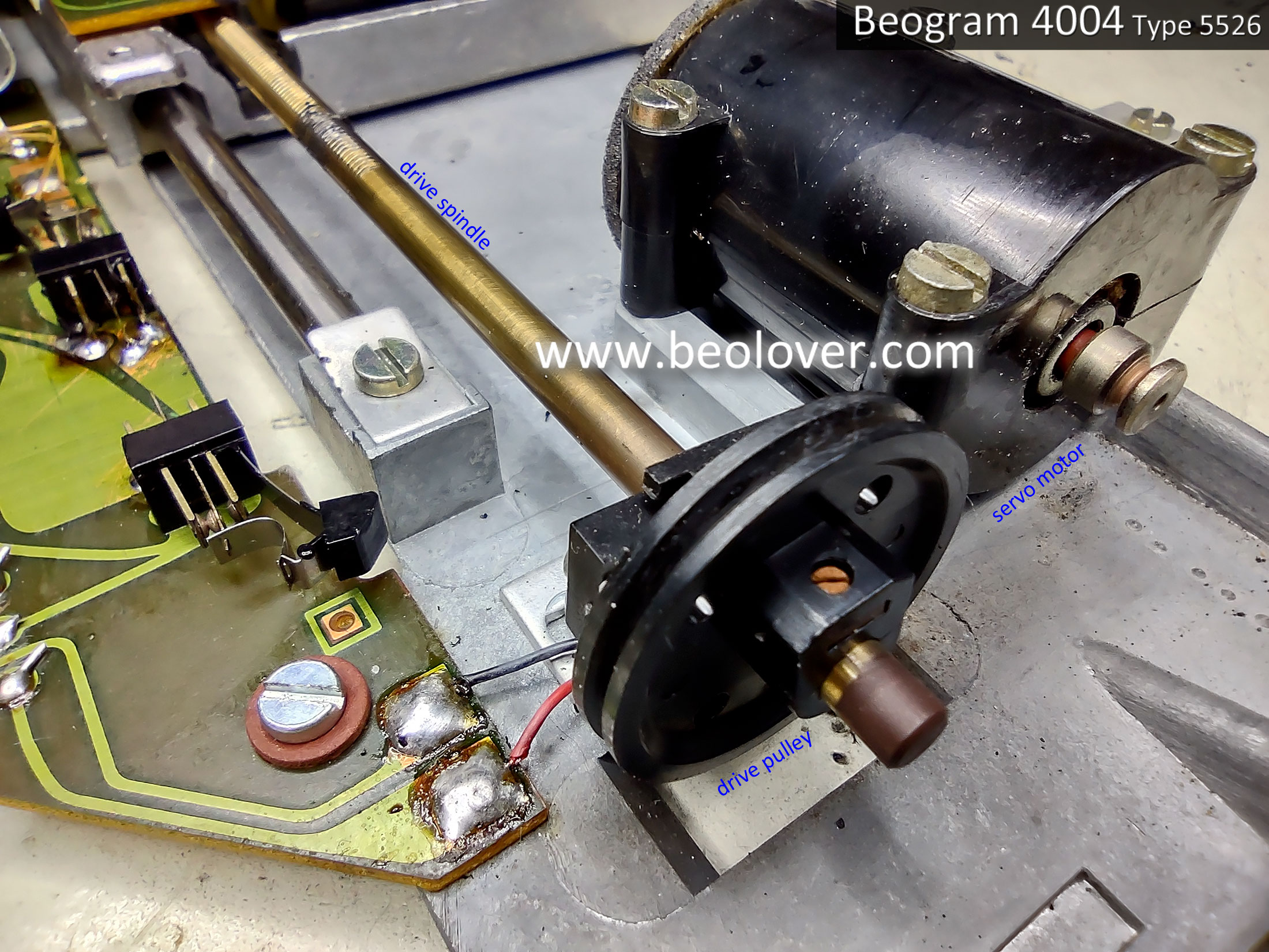
Next, I removed the servo motor and the tangential drive spindle/pulley assembly.


Here is the servo motor opened up.
The foam padding is still intact but pretty brittle. It will eventually completely dry out and start breaking into pieces so I will replace it with new vibration damping material.


I cleaned the spindle with a brush and some alcohol. 
I removed the original, plastic pulley from the spindle and installed an aluminum pulley.


Next, I removed the original tracking sensor lamp assembly to prepare for the installation of the replacement Beolover Beogram 400x tracking sensor lamp assembly.


With the tangential drive spindle removed the tangential arm assembly can easily be slid up and down the two guide rails.  This is a good time to clean them before applying new grease.


That is all I am going to do on the floating chassis components for now.
It is time to move on to the work on PCB 1 and PCB 8.
Once those are complete I will return to the floating chassis to install the new Beolover tracking sensor lamp assembly along with replacing the fixed arm, record detection lamp (also a Beolover lamp assembly).

Here is the before photo of the Beogram 4004 Type 5526 PCB 1, the main turntable electronic control circuits.


Here is the PCB 1 after photo...after the capacitor replacement has been done, a new platter speed selection relay has been installed, new trimmers for the platter speed control, new trimmer for the position sensor calibration (1R88), new 1TR3 transistor for the record detection circuit and a corresponding 2MΩ trimmer for calibrating it (in place of the original 1MΩ, 1R26).


Note: As we normally do, the 2MΩ, 1R26 trimmer is installed temporarily on the trace side of PCB 1 so it is accessible when it is initially set (to calibrate 1TR3).  Once the calibration is done, the 1R26 trimmer will be moved to the component side of PCB 1.  You can also see that a WIMA 4.7uF capacitor has been located on the trace side of PCB 1.  That component will stay on the trace side as I don't want any possibility of it physically interfering with the floating chassis mount that sits below PBC 1.
Regarding transistor 1TR3...the original transistor measured with an Hfe below 500 so I installed a new transistor that has an Hfe of above 500.  Together with the 1R26, 2MΩ trimmer there should be no problem adjusting the record detection signal per the service manual.

I also worked on the Beogram 4004 Output circuit board (PCB 8).
The Beogram 4004 Output circuit board has a lot more components than a Beogram 4002 from the same time period (i.e. a Beogram 4002 Type 5523).  The reason for that is the Beogram 4004 has a remote control circuit that ties in with a Beomaster 2400 receiver.  

Here is the before photo of the PCB 8 board.


Here is the after photo.


Things to note on the updated board are the replacement of the muting relay and the addition of a grounding selection switch.

We install this type of switch on all of our Beogram 400x turntable restorations to provide an easily accessible control over the way the signal ground and chassis ground are configured inside the Beogram for the phono cable.  Some phono amplifiers need signal ground and chassis ground tied together or else there is hum on the phono signal.  Other phono amplifiers do not.  The switch makes both options available for the owner.

The project is getting close to actual record play now.

In the next post I will install the new Beolover Fixed Arm Lamp Assembly,  the Beolover Tracking Sensor Lamp Assembly, lubricate the tangential arm assembly and perform the service manual tonearm adjustments.

Tuesday, April 12, 2022

Beogram 4002 (5523): A New Arrival from Colorado - First Impressions

I recently received a Beogram 4002 (Type 5523) from Colorado for restoration. It arrived well-packaged in a Beolover issued double-box. This is how the deck looked like when I put it on my bench:

The hood is pretty scratched up, but it seems the hinges are still o.k, and most of the scratches are on the outside. This means it could be polished back to a decent state. I removed the hood and found nice aluminum surfaces and a keypad that only shows light use-traces (the coating of the touch areas is slightly shinier than the rest).
The plinth corners are near-pristine:
The next step was removing the aluminum plates. When I pulled the plinth forward for their release, it turned out that the metal frames that are glued to the plinth are coming loose (a frequent issue due to decaying contact cement):
I also found a single spring, which is from one of the hood-mounting bolts (these springs keep the bolts propped up for easy mounting of the hood):
After removal of the hinge bar in the back of the deck it turned out that the second spring seems missing. Luckily, there are suitable replacements available.
Below deck this Beogram appears mostly original without obvious traces of previous 'human interaction'. This is the best state for a restoration, since it makes it much less likely to run into unexpected problems.

I plugged the unit in and pressed start. The carriage started moving and the platter motor spun. The carriage stopped at the LP setdown point and the solenoid actuated for arm lowering. Then I pressed Start once more and the carriage traveled to the inner turnaround point, and then returned to its home position. All good signs!
In summary, this unit is a pretty good starting point for a restoration, which will return this Beogram to a like-new functional condition.


Saturday, March 26, 2022

Beogram 4002 (5513): New Arrival from Arizona - A First Look

I recently received a Beogram 4002 (Type 5513) from Arizona for a complete functional restoration. The unit arrived without its hood. It came in a Beolover shipping container. An excellent approach for trouble-free shipping. 

This is the unit as extracted from the packaging:

A bit dirty, but overall not too bad, except for the completely worn keypad:
I hope we will soon be able to professionally restore these keypads. On the positive end of things, the plinth is in a pretty good condition. The corners are almost pristine:
I removed the aluminum plates and had a look below deck:
This unit looks mostly unadulterated, a perfect starting point for restorations. There are fragments of decayed transport lock bushings all over the place, nothing unexpected in this vintage:
As usual the plastic pulley on the carriage spindle is cracked and my customer said he glued it to the shaft (shudder!...;-). It will be interesting to remove it from the shaft for installing an aluminum replacement. The belt definitely also looks 'end of life':
I was told this unit did some traveling in an RV for a few years (that is what I call 'roughing it'!...;-). Maybe this is the reason that the floating chassis springs are pretty rusty:
This is nothing really worrisome, just looks a bit, well, rusty!...;-).
After this first inspection, I plugged it in and pressed START. The carriage sluggishly started moving and the arm found the LP setdown point and - nothing! No solenoid action. I pressed STOP and waited for the return of the carriage to its home position. Then I manually operated the arm lowering mechanism a few times and tried again. This time the solenoid acted. So it seems there are just the usual hardened lubricants at play, and a thorough cleaning and re-lubricating should do the trick. The DC platter motor made some noises while the above happened. This is also not unexpected. These motors usually have dry bearings and they need to be re-infused with oil before the deck can be used again.

In summary, this is a pretty decent starting point for a full restoration, and I expect this Beogram will soon play like-new, and hopefully also look like-new after installation of a refurbished keypad!