Featured Post

Beolover SyncDrive: DC Platter Motor Replacement for Beogram 4002 and 4004 (Type 551x and 552x)

Late Beogram 4002 and the 4004 (Types 551x and 552x), which have DC platter motors instead of the earlier synchronous AC motors usually suff...

Showing posts with label tracking force. Show all posts

Monday, June 5, 2023

Beogram 8000 Type 5513: Tomball Texas Project Final Adjustments and First Record Play

The Beogram 8000 restoration project from Tomball, Texas is playing records again.

To get to this point I had to perform some remaining adjustments.

First was the forward/reverse scanning LDR adjustments.  Those are for the tonearm forward and reverse buttons on the control panel.  The Beogram 8000 uses a couple of LDR devices (resistors that change value when light hits them) and a rocker spring that is an aperture for the light source to strike the LDR.
The steady state voltage level of the two LDR devices (forward and reverse) should be around 620 millivolts (DC). I like to set them at around 650 mVdc. They are dialed in by an adjustment screw that affects the amount of light to the sensor.  

The adjustment screws are a rather coarse adjustment and is why I installed the little test connector to make tweaking the setting easier (especially after the Beogram 8000 is fully reassembled in its cabinet).

Here are the forward and reverse, steady-state measurements for the LDR devices.


I also measured the +5 VDC, +15 VDC and -15 VDC power supplies again.
I measured the +5 VDC at the filter capacitor inside the PCB 2 assembly that supplies power to the microcomputer (uC).


I checked the +15 VDC voltage going into the regulator and coming out of the regulator.


I measured the -15 VDC off the 1TR19 collector where that voltage regulation output is located.


From there I moved to making some measurements on the oscilloscope of the speed sensor, the two position sensors and the record detection sensor.

For the speed sensor I measured the raw signal coming off the sensor assembly, then at uC (2UI1-40) after the signal has been filtered.

Here is the measurement point for the raw signal from the sensor assembly (P4 pin 7).


Here is the measurement point on 2IC1-40 (uC).


...and here is what the oscilloscope shows.


Next are the measurements for the two position sensor signals and the record detector signal.
I made those measurements with the tangential arm assembly moving forward and in reverse.

Here are the measurement points.


...and the oscilloscope measurements.


The supply voltages and sensors all looked good so I moved to the final two adjustments on this Beogram 8000.

The first adjustment was to check the phono cartridge tracking force and adjust it if necessary.
The second adjustment was to set the sensitivity of the tangential tracking sensor.

For both of these adjustments I need the Beogram 8000 where I can operate it but I don't want the platter to rotate.  With a belt driven turntable it is just a matter of removing the belt.
On the Beogram 8000 it means disconnecting the P4 connector on PCB 1.  

Just to be safe, disconnect and connect the cables with the Beogram unplugged from the wall.


The tracking force and tracking sensitivity are both adjusted on the tonearm assembly.


The tracking force for the phono cartridge is always available for the owner to set using the small adjustment slider under the tracking force scale (along the side of the tonearm).
What I do during the service manual checks is calibrate the tracking weight so it is as close to 1 gram as I can get it with the slider set to "1" on the scale.

To do that I use a digital scale and adjust the tracking force counter-weight position as necessary to get 1 gram on the measurement.

Note: I make the tracking force measurement with the platter turned upside-down because it is flat enough for the measurement scale to rest on.


On the tracking sensitivity adjustment the procedure is to place a test record on the platter, then advance the tonearm over a test track (usually in the middle of the record) and set the arm down.
I also set the arm down (with a phono cartridge attached) before that and make sure that the tracking sensitivity isn't too sensitive where the arm starts moving forward by itself.

The arm should lower straight down and the phono stylus sits in the record groove with no forward advancement of the servo motor (that drives the tonearm assembly).

Next, the platter is manually rotated and the servo motor is observed for movement.
The servo motor should advance the arm within one or two revolutions of the platter to begin with, then every platter revolution after.

Should the tracking sensitivity require adjustment, there is a small adjustment screw on the side of the tangential arm assembly...shown here.


That completes the Beogram 8000 adjustments.  Now it was time to actually play a record.

I will do more complete record play testing later, when the Beogram 8000 is fully assembled.
At this point however, I like testing record play with my Workshop Beomaster 8000.
Besides being anxious to listen to a record, now is a good time to check the record play functions.
If there was a problem, the Beogram 8000 is already open for trouble-shooting.

I like testing with a Beomaster 8000 because the two components are integrated with their controls.
Pressing Play on the Beogram 8000 will cause the Beomaster 8000 to turn on and switch to the phono (PH) source.  Pressing PH on the Beomaster 8000 will cause the Beogram 8000 to start playing a record.

Note: I keep my Workshop Beomaster 8000 opened up for servicing at all times so I can use it for Beomaster 8000 board testing. Just like I keep my Workshop Beogram 8000 opened up.

The first record play test performed perfectly so I just relaxed and finished the day listening to some vinyl.






Monday, February 6, 2023

Beogram 8002 Type 5633: Final Adjustments and First Record Play

In wrapping up the Beogram 8002 floating arm assembly and electronic control restoration work I took some time to measure the activity of the Beogram 8002 servo motor and its control signals.

To get to that point on this Beogram project I had to adjust the tracking force of the phono cartridge and set the sensitivity of the tracking sensor.

Those tasks are performed with the Beogram 8002 plugged in and able to operate but with the platter motor disabled.  The way that is done is to disconnect the Beogram 8002 P4 connector from PCB 1 (with the Beogram unplugged as well of course).


The arm assembly can now operate and be lowered onto the disabled platter to measure and adjust the tracking force of the tonearm.  

This is done with an MMC cartridge installed on the tonearm and a scale to measure the tracking force.
I use a digital scale as shown in the next photo.  
My method of setting the tonearm counterweight is to set the tracking force knob to 1 gram on the slider indicator, then adjust the counterweight adjustment screw so the digital scale measures 1 gram with the arm lowered.


The tracking sensitivity is performed by placing a test record on the platter, moving the arm over the record and lowering the arm on a track in the center of the vinyl record.  The platter is then manually rotated as you observe the movement of the Beogram servo motor drive belt.  The pulley and motor should move (to advance the arm) within 1 revolution of the platter.  After that you should see the arm advance in varying small increments depending on the characteristics of the track. The tracking control should be keeping the arm tangential to the record.

Here is the adjustment screw for the tracking sensitivity.


Also shown in the photo is the SO (Switch Off) switch. The SO switch turns off the servo motor when the arm assembly returns to the Standby position and the SO switch enables the arm position counter during Play.  The SO switch can be moved slightly with its adjustment screw to manipulate the actual setdown position of the stylus on a record.


This section from the Beogram 8002 schematic shows the servo motor and its control signals.


The diagram shows the signals from the Forward and Reverse scan LDR controls feeding into the servo motor drive control amplifiers (1IC2).  That is why it is important to set the steady-state voltages on the scanning LDR devices.  This is where I use my little test connector that I added to the Beogram 8002 control panel board.  Here is a photo of the forward and reverse scanning LDR devices after I adjusted their voltages.


The LDR voltages (when Play is pressed and the tonearm is paused) should be set to 620 mV according to the service manual.  A value from 620 mV to 700 mV is actually okay.  I usually aim for 620 mV to 650 mV.

The Beogram 8002 servo motor belt is important to get right. It should not be too tight or it will damage the servo motor over time and the tangential arm assembly control will not operate correctly.

Here is a photo of the servo motor belt.


I have discovered that these servo motors (DC motor) can sometimes start squealing as they age.
It is possible to add a little synthetic turntable oil to the shaft of the servo motor (not on the pulley of course). 

That turned out to be the case with this Beogram 8002.  The pulley started making quite a racket the more I ran tests on the turntable where the arm had to move.

Once I applied a drop of oil and changed the servo motor belt, the operation returned to normal.

For monitoring the operation of the servo motor during record play I selected the arm LIFT command, one of the arm position sensors, the forward servo drive command at the amplifier input and the actual servo drive signal at the motor.

Here is a photo of the measurement points.


With these four measurement points I could view the servo motor as it goes from Standby mode to record play.  

That sequence results in the Beogram 8002 driving the servo motor at fast speed when the Play button is pressed until the arm reaches the setdown point.  At that point the servo motor slows down and stops at the setdown position.  The LIFT command is energized and the arm lowers onto the record.

The setdown point should be on the record lead-in groove and that will result in the servo motor driving the arm through the lead-in groove and stopping at the first record groove with music content.
Now the tracking control will advance the servo motor as the phono stylus moves along the record groove.  That path moves the tonearm inward towards the platter spindle.
The movement of the arm will trigger the servo motor to advance the arm assembly so it remains tangent to the record.  That controlled movement is dependent on the tracking sensitivity adjustment procedure performed earlier.

Here are the oscilloscope screen captures.


Here is a measurement that captures the Press Play event through to tracking the first record groove.

Notice that at the point the record is being played that the little "humps" in the Servo Motor signal (at P1-1) are when the motor is advancing the arm a bit.  Also note that the position sensors do not register a pulse for every motor advancement. That is because the pulses on the position sensors occur when the sensor lamp hits the sensor between the openings in the sensor wheel.  As can be seen on the 2IC1-28 sensor in the photo, there are times when the motor is advancing but the sensor signal is quiet. The sensor wheel is blocking the light during that time and the motor is only slightly advancing the wheel. 


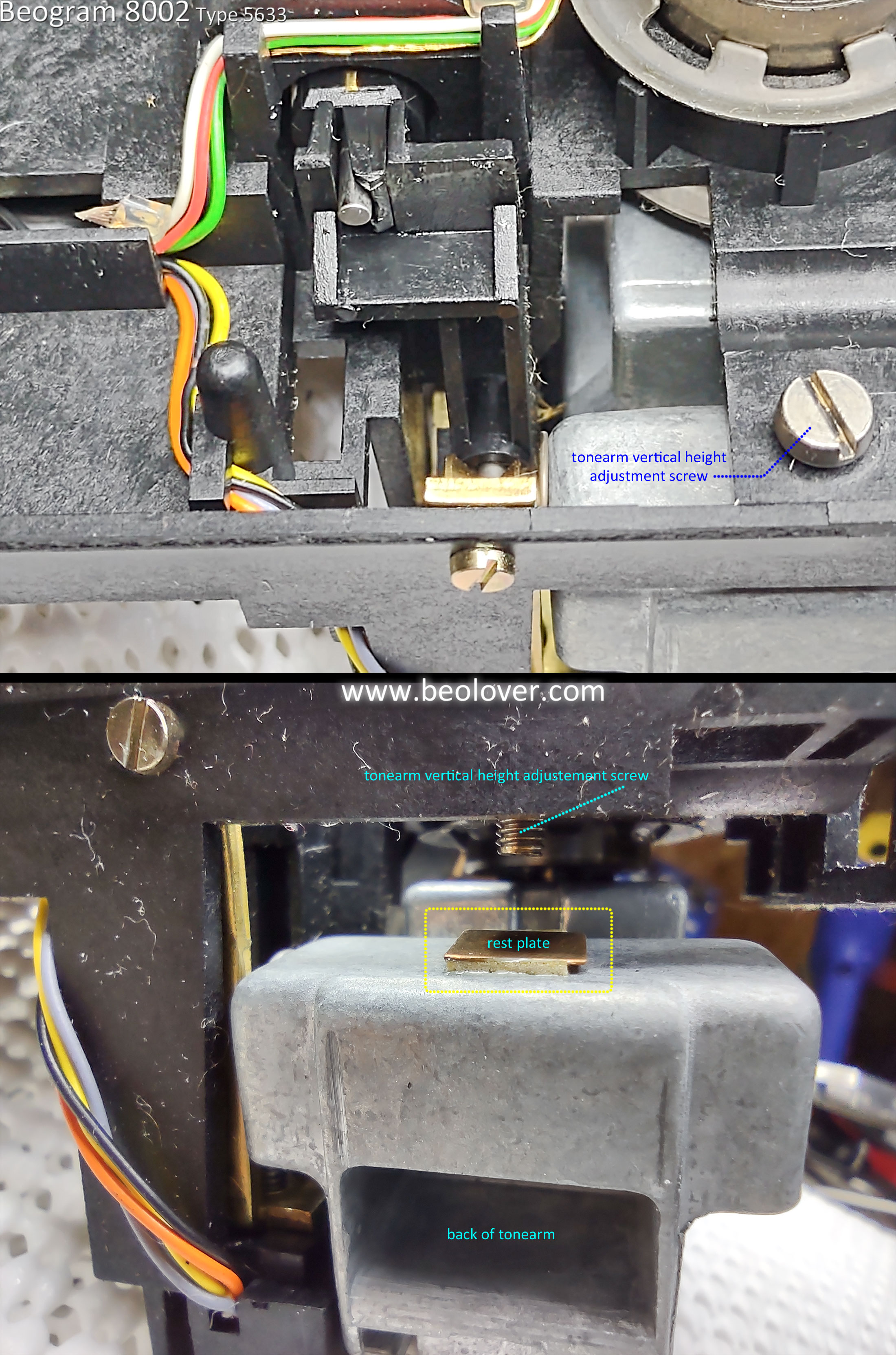
One more service manual adjustment to mention is the distance from the platter surface to the top of the sensor arm.  That distance should be adjusted so you get 19.5 mm from the platter surface to the top of the sensor arm.  There is a screw at the top of the sensor arm for that adjustment.


This adjustment is to set the distance of the phono cartridge stylus at a safe distance from the surface of a record. It is easiest to perform this when the floating chassis assembly is apart.  The reason for that is while setting the end of the sensor arm position is easy from the top of the arm, the corresponding adjustment of the tonearm height is made underneath the tangential arm assembly.  That means pulling up the tangential arm assembly from the guide rails and spindle again.


As I said, the result of this adjustment is so the end of the tonearm is where the stylus can safely scan over a record with good clearance.  This adjustment has nothing to do with the Vertical Tracking Angle of the phono stylus.  On a Beogram 8002, the Vertical Tracking Angle is fixed and cannot be adjusted.


All of the floating chassis and sensor adjustments are complete on this Beogram now.
The completed floating chassis assembly can play a record all the way through and I can test the record play by connecting up these Beogram 8002 components to my Workshop Beomaster 8000.

While I am testing the record play I can start in on the Beogram 8002 cabinet restoration tasks.

Wednesday, November 16, 2022

Beogram 8000 Type 5613: Wisconsin project is ready for record play

I finished the service manual checks and adjustments on this Beogram 8000 turntable.
The power supply voltages look good. The forward/reverse scanning LDR adjustments are set.
Tracking force is calibrated as well as the record tracking sensitivity.

A quick workshop test play of a record shows that the Beogram is ready for some record play listening tests so I will install the components back into the Beogram cabinet and enjoy some records.

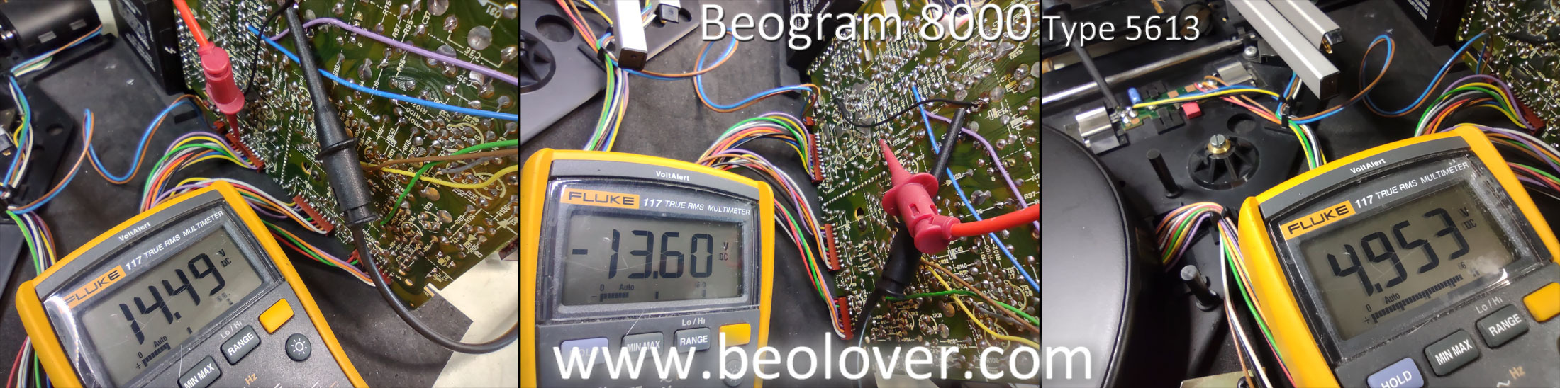
Here are the supply voltage checks at the filter capacitors and at the output of the regulators.
From left to right are +15 VDC, -15 VDC and +5 VDC.


In this photo I show using my little three pin test connector for adjusting the forward and reverse scanning sensors (LDR devices).  I like to set the idle voltages for these around 650 mVdc.


Next was calibrating the tonearm tracking force at the 1.0 gram mark on the adjustment scale.
I adjusted the counterweight at the back of the tonearm until the 1.0 gram mark on the adjustment scale measured 1 gram on the scale.


The final adjustment is for the record tracking sensitivity.  This is the adjustment where the P4 connector is disconnected from PCB 1 so the platter doesn't turn.  

The procedure calls for manually turning the platter with a test record.  The stylus is dropped onto a track in the middle of the record and the tracking sensor sensitivity is adjusted so the tangential arm servo begins advancing the tonearm assembly between 1 or 2 revolutions of the platter.  After that the servo motor should advance the arm every revolution of the record.


After a few iterations of the adjustment screw the sensitivity was set.

Before putting the Beogram 8000 all back together in its cabinet I wanted to listen to a couple of records on it while it is in the workshop.  I connected it to my Workshop Beomaster 8000 and gave it a listen.  Using the Beomaster 8000 also tests the remote control functionality between the Beogram 8000 and the Beomaster 8000.


The MMC-20CL cartridge played beautifully on the Beogram.  My Beomaster 8000 is connected to a pair of Beovox S75 speakers and did their part in the record play enjoyment :-)

Note: I keep my Workshop Beomaster 8000 opened up all of the time. It is fully functional where I can use it to listen to music while I work but it is always available to perform board testing with and that is its main purpose in the shop.

Saturday, June 25, 2022

Beogram 4004 Type 5526: Restoration work - Part 4

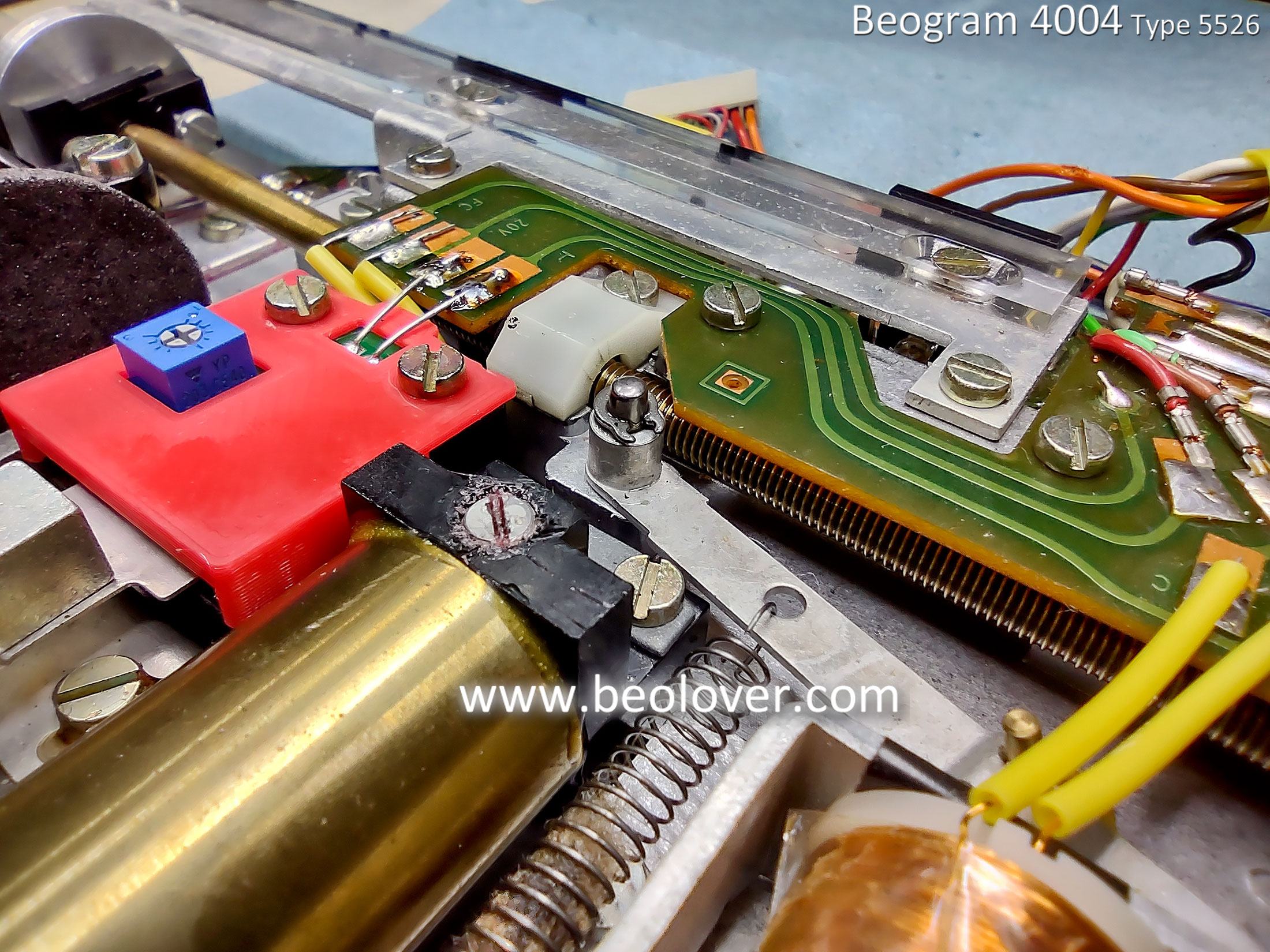
I wrapped up the floating chassis component tasks by reassembling the tangential arm assembly.
During the reassembly I performed some key lubrication tasks like new PMX - 200 silicone fluid in the lowering damper and a mixture of Rocol MTS 2000 grease with Mobile NUTO H32 oil.  
More modern lubricants are available today but I have plenty of the original lubricants called for in the Beogram 4004 service manual so I like to use those.

I applied some Molykote DX paste (grease) to the two tangential arm assembly rails first.


Then I opened the tonearm lowering damper to clean it and apply some PMX - 200 silicone fluid.


Next I mixed some Nuto H32 oil with Rocol MTS grease for the lubrication mixture on the tangential arm assembly spindle.


The Beogram 4004 tangential arm assembly components can now be reassembled on the floating chassis.


At this point I like to check the tonearm tracking force calibration.
The parts are easy to get to so it is a good place to calibrate the tracking force.


The Beogram 4004 floating chassis (and components) are ready to go into the base cabinet again.


Friday, August 6, 2021

Beogram 8002 From North Texas: Service Manual Adjustments to Record Play

In this post I will show the service manual adjustments I had to make for this Beogram 8002 restoration and go over the power supply voltage measurements. Once those are done I can check out the initial record play on the turntable. I will also take a look at the signals from the record detection circuit, the position sensor and the platter speed sensor to make sure they look healthy.

To be able to start playing a record I need to check a couple of things with the tangential arm assembly.
I have to make sure the distance from the platter surface to the top of the tonearm is 19.5 mm (per the service manual).  

This is done by setting the fixed arm height to the required 19.5 mm value, then adjusting the tonearm to be horizontally parallel with the fixed arm.

In order to maneuver the arm assembly over the platter for this measurement and later, adjust the tracking force and tracking, I need to be able to move the arm but have the platter not spin.

That can be accomplished by unplugging the Beogram 8002, then unplugging the PCB 1 P4 connector.
Plugging the Beogram 8002 back into the AC outlet now permits operation of the Beogram without a moving platter.


Checking to see where the fixed arm height was to begin with I discovered it was low.


There is a screw at the rear of the fixed arm that is used to adjust the height for this service manual adjustment.


Using the fixed arm height adjustment screw I was able to set the required 19.5 mm distance with the platter.


That set the fixed arm height to be correct but of course the tonearm height must also be set at the same height.  You can see that they are no longer aligned horizontally.


The tonearm height adjustment unfortunately means I must take the tangential arm assembly off the spindle and rails once again because the adjustment screw is underneath.


Now the arms are horizontally parallel again and 19.5 mm from the platter surface.


The next service manual adjustment to make is calibrating the tonearm tracking force.
In the photo above you can see that I left the slider control for the tracking force set to 1 gram.
For the adjustment I will attach a phono cartridge and see what the actual force is. If it needs adjustment I will move the tonearm counterweight so I measure 1 gram.

Here is the final tracking force measurement after a few adjustment iterations with the counterweight.


One more service manual adjustment now until I can play a record.
The tracking sensor that detects tonearm movement as a record is being played needs to be calibrated per the service manual so its sensitivity is correct.

There is a single adjustment screw on the side of the tracking sensor assembly for making the adjustment.


The adjustment is performed by setting the tonearm and phono cartridge down onto a test record.
Again...the platter must not be turning.

The service manual specifies using a Bang & Olufsen test record that I have never been able to find.
In its place I have a couple of records that I use for the adjustment and do so by checking the tracking sensor sensitivity on several different tracks.

The procedure says to lower the arm, then manually rotate the record while observing the servo motor that moves the arm. When properly adjusted the servo motor should begin moving the arm after 1 to 3 revolutions the first time (after the arm is lowered)...then every platter revolution after that.

Once the tracking sensitivity is set the Beogram is unplugged so the P4 connector can be plugged back in to PCB1.  That will allow the platter to move again.

Here is the Beogram 8002 playing its first record since the restoration work was done.


I observed that the tonearm tracked correctly and that the arm assembly returned to the standby position automatically after record play.

It appears that the Beogram 8002 is functioning properly again.  The restoration tasks all look correct.
To really check the electronic functionality though it is a good idea to measure the power supply components for +15, -15 and +5 VDC.  I also like to view the sensor signals on an oscilloscope.  That is just a good confirmation that the signals look like they are expected to. 

Here are the power supply measurements.

+15 VDC : The filter capacitor C27 and the regulated value at P2-9.


-15 VDC : The filter capacitor C29 and the D26 anode.


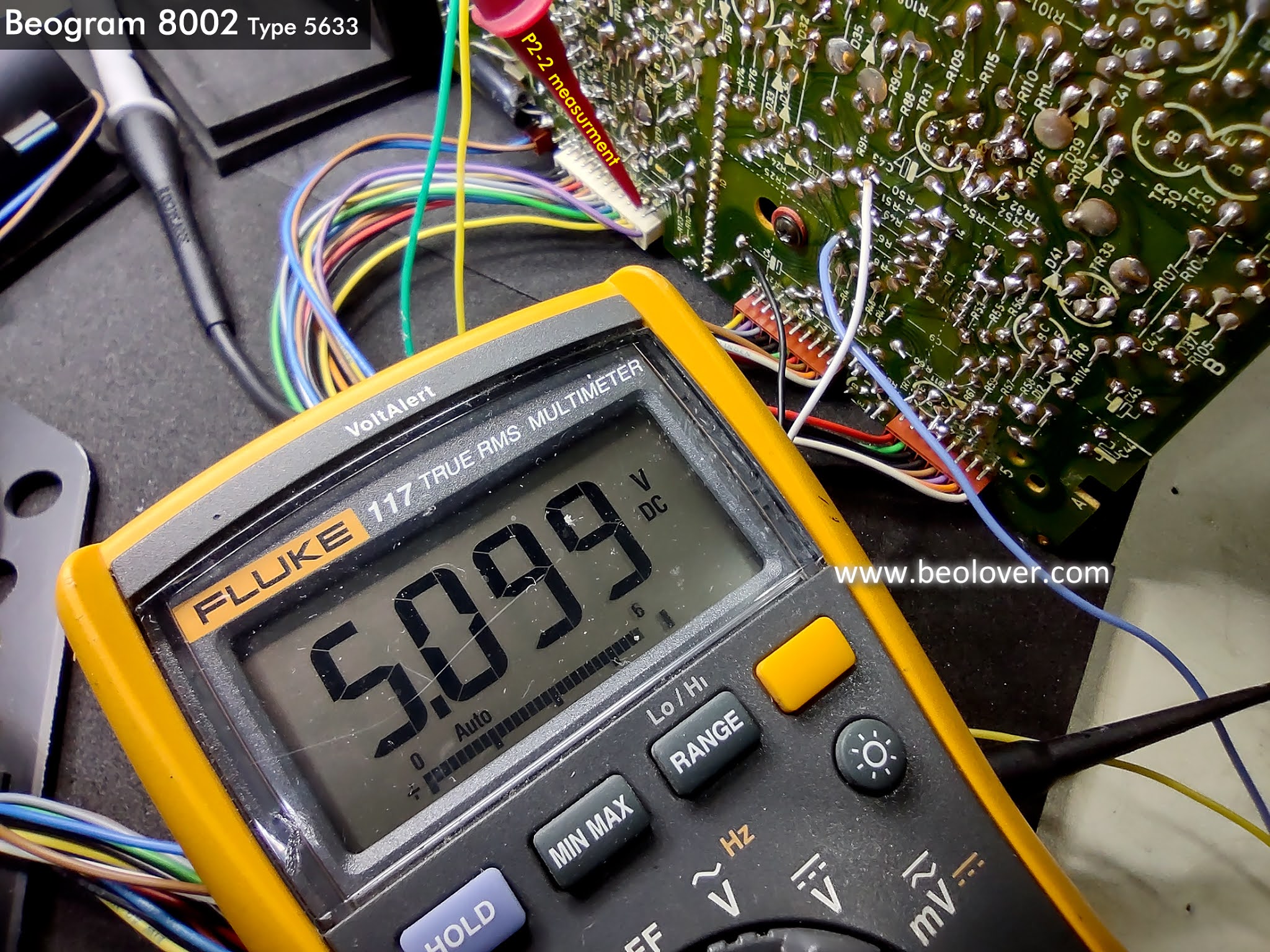
+5 VDC : The filter capacitor C24 and the regulated value at P2-2.


Everything looks as expected with the power supply voltages.

In using the Beogram I could see that the forward and reverse scanning controls work well but I hadn't actually measured and set them. 

To do that I use my little test connector that I installed earlier. It has the ground, the forward LDR signal and the reverse LDR signal.  Both signals should be set so they measure between 620mV and 700mV when the Beogram 8002 is in Play mode and not scanning.

Here is one of the initial measurements.


I like to set the value around 650mVolts.
It is hard to be really precise on the setting because the adjustment screws only provide a very coarse adjustment.


I will wrap up the checks on the oscilloscope.
Here are the measurement locations again for the oscilloscope probes.
I connected to the arm detection sensor, the two arm position sensors and the platter speed sensor.


As a starting reference point here are sensor signals when the Beogram 8002 is in Standby mode.


Pressing the Play button with an empty platter will cause the Beogram 8002 to start rotating the platter, lock in the speed at 33.33 RPM and scan for a record to play.  At around the 17cm mark the platter speed will switch to 45 RPM.  Shortly after that, if no record is found the Beogram will stop and return the tonearm back to its standby position.

Here are the oscilloscope events for that.


In the above photos you can see how the arm detector and speed sensor signals vary at 33.33 RPM and 45 RPM.

Here are the signals again but with a record on the platter and as the Beogram plays the record.


The arm detector signal does its usual start up pulse but then settles at 0V because the record is on the platter covering up the reflective patterns.
Also notice that the position sensors are pretty constant as the tonearm is scanning.

Once the tonearm is lowered to play the record the platter speed is constant, the arm detector is at 0V and the two position sensors are at varying values due to the servo position control making incremental movements to play the record.


I think this Beogram is ready to reinstall in its cabinet and move to some record play listening tests for a while.