Featured Post

Beolover SyncDrive: DC Platter Motor Replacement for Beogram 4002 and 4004 (Type 551x and 552x)

Late Beogram 4002 and the 4004 (Types 551x and 552x), which have DC platter motors instead of the earlier synchronous AC motors usually suff...

Showing posts with label arm position sensor. Show all posts

Wednesday, July 4, 2018

Beogram 4002 (5513): Service Manual Adjustments & Preparing for Use

I left off in the last post with the keypad cleaning, deoxidizing and the RPM panel. The keypad response is immediate but the cueing up and down button is too sensitive now. I will have to revisit that switch. There was a delay in the RPM panel re-installation because the molded, acrylic mounting fixtures were cracked. That is very common with these Beogram 4002 turntables. Often they are completely broken. Luckily the mounting fixtures on this Beogram just had one crack in each one and were still intact. I pressed the mount fixture together as I applied acrylic repair fluid in the crack. It dries very quick. That repair by itself is not strong enough if the RPM panel is removed and reinstalled very many times. To supplement the acrylic glue I cut two strips of Dura-Lar and put one strip on either side of the mounting block. I use Araldite AB rapid epoxy. It is clear.


The patched mounting blocks attach to the aluminum frame by set screws underneath.


One thing to note is the mounting screw for the keypad and RPM indicator panel is right underneath the RPM panel so whenever there is a need to get to the keypad buttons or the phono output board, the RPM panel has to be removed. That is why reinforcing the mounting blocks is important.

Here is the panel back in place.


Next I want to make sure the voltages and signals of the Beogram detectors are good.
First up is the 4D1 LED and its 4IC1 optical sensor that detect where the tangential arm is. Markings in the acrylic slide alter the LED light to the 4IC1 sensor and Beogram circuitry reacts to those changes in the signal.

The service manual check for this sensor is to measure the collector of the 4IC1 sensor when a transparent section of the slide is between the LED and the sensor. The voltage level at the 4IC1 collector should be around 5V.  If it is not, the 1R88 trimmer (on the main board) is adjusted to set the voltage needed.

These pictures show the adjustment.


This is an important adjustment because the run-out groove detection at the end of playing a record is dependent on this voltage level being set correctly.

Next though is the fixed arm sensor that detects if a record is present (and if it is okay to lower the tonearm). The fixed arm has a light source that shines down on the platter. The reflected light is read by an optical sensor. If there is a record on the platter the reflected light will be at a low level and won't vary. That steady, weak signal is interpreted by the Beogram arm lowering logic as okay to set down the stylus. If there is no record the black ribs on the platter will affect the reflected light so that it returns as pulses to the sensor. The pulses cause the arm lowering logic to not allow the stylus to be lowered.

Obviously it is important for this signal to be working and is at a proper level.


This sensor is providing pulses that are above the required 6 volt level. No danger of accidently lowering on an empty platter.

I need to check the end groove, run-out stop circuit but first I will perform some more mechanical checks and adjustments to get the Beogram ready for record play.

I caught a break on the platter to tonearm height adjustment. The distance was already at the required 23mm.


The arm lowering limit needs to be set so the tip of the stylus is about 1mm from the top of the first platter rib. This is a safety feature that prevents the cartridge from damage should the record detection circuit fail.


Another remaining mechanical adjustment is to check the tonearm for length and parallelism.
I run a string tangential to the Beogram arm assembly then check that the stylus travel path follows the string.


The check that the tonearm is 7.7mm distance from the fixed arm and that they are parallel were checks I made earlier in the restoration when I took apart the tonearm assembly (for the oil cleanup).

We are getting close to record play now. At this point the tracking sensor sensitivity needs to be fine tuned, the run-off stop needs checking and the platter speeds need to be dialed in.

The tracking sensor adjustment went fairly smooth. It still took quite a few iterations to get the sensitivity set where the tangential arm motor moves after each revolution (2±1 revolutions initially, 1 revolution after that).

The run-off stop check measured good on the oscilloscope.


I was able to easily adjust 1R14 and 1R15 trimmers (on the main board) to set the 33⅓ RPM and 45 RPM speeds using the Beolover RPM tool.


Whew! A lot of adjustments and checks on these Beograms. I still love them though. What a great turntable design.

Now for a break for some food and fireworks (not with the Beogram :-).  Then I will do a quick adjustment on the keypad cueing button. After that I should be lying down and listening to some records.

Wednesday, June 27, 2018

Beogram 4002 (5513): Electrical Work and Initial Tracking Adjustment

On to the electronic board restoration tasks. There is the main control board to recap and change the RPM relay (plus RPM trimmers) on. Then there is the output board with its phono muting circuit. It should be noted that the muting relay is the only electrical component other than wiring that is involved with the phono audio signal. Most of the electronics in the turntable are for controlling the platter motor, tangential arm, indicator lamps and operator controls. Those circuits are not in the audio path.

Here is the main control board before the recap. It has a few electrolytic capacitors and quite a few tantalum capacitors. I will change the capacitors that are 4.7uF and above with new 105°C, Nichicon capacitors. On the values smaller than 4.7uF I will use WIMA MKS polyester capacitors. When there is room I usually replace the 4.7uF capacitors with WIMA MKS as well but they are too large for this application. Another thing to note is that I will change the 1C10 electrolytic capacitor from its original 0.47uF value to 10uF per Beolover's test results of the restored platter motor. That value was determined to give the best speed stability with this particular motor.


Here is the restored main board.


Now the output board before


...and after. Note that I installed our usual grounding switch so signal ground and chassis ground can be engaged or disengaged depending on the owner's needs.


I am now ready to see how this Beogram acts with its mechanical components cleaned/lubricated and the electrical components updated. For the first electrical power on test I removed the tangential arm motor belt and left the platter off. That way if something is not right I don't have to worry about a moving component going somewhere. I also removed the arm position scale from the tangential arm transport to take a look at the switches and the position sensor lamp.


With the Beogram plugged the main reservoir capacitor shows that it is at just over 30 VDC which is good. The fixed arm sensor lamp is illuminated and so is the 33 RPM speed indicator lamp. The platter motor and tangential arm motors are turning. That is expected since the position scale is off and there is nothing there to turn the SO switch off.

However, there is one fault I can see right away and that is the tangential arm position sensor lamp is not lit.


Without the arm position sensor lamp the control logic cannot determine where the tangential arm assembly really is.

I replaced that with an amber T-1, round LED.


The replacement LED I use has a wavelength of 591nm and luminous intensity value of 13000 mcd. The viewing angle is 15°.  The important thing here is that the sensor detects the light and is able to supply the control circuit with the proper voltage level. I will do a more detailed check of that sensor voltage later when I go through the service manual adjustment/checks.

Here is the new position sensor lamp installed and working.


This is a good time to prepare the initial setting for the tangential drive tracking sensor. I had to disassemble most of the tracking sensor components when cleaning up the oil so there is a good chance that the tracking alignment is off now. I visually set the tracking sensor aperture to be centered but that was just a guess.


Using the aperture position adjustment screw I set the aperture in a position where the arm pivots easily and, when the arm is lowered, the tangential arm drive motor doesn't try to drive it somewhere.
Then I play with the tracking sensitivity adjustment screw and the aperture position to find a place where the sensitivity screw can affect the arm moving forward (when it is lowered). The goal here is to set the arm tracking control where I have enough play in the tracking sensitivity screw to lock in the tracking later (during the service manual adjustments). With that set up I can tighten down the aperture position screw.

Now on to replace the speed indicator lamps from the original incandescent lamps to Beolover's replacement LED boards. Those are the final piece of obtaining optimum platter speed stability.

Wednesday, July 26, 2017

Beogram 4004 Type 5526: Tangential Arm Position Detector

Just a quick and short update...
I didn't get as much bench time as I wanted the last couple of days but I did sneak on long enough to connect power and adjust the Beogram's tangential arm position detector voltage.

Just like I did on the previous Beogram 4002 (Type 5513) project, I needed to verify that the base voltage of 1TR17 is at a nice 0.7 VDC when the light source 4D1 is illuminating the tangential arm position sensor, 4IC1.

It was a little off so adjusting trimmer resistor 1R88 was necessary to bring the voltage down. This picture shows the initial adjustment.


Once I re-attached the position scale I re-checked the voltage at 1TR17 base with the 4D1 LED at a transparent part of the scale.

I then ran the Beogram tangential arm through some of its operations. Everything worked great.


Later tonight I will measure and adjust the new 2M ohm trimmer for the fixed arm record detector.


Wednesday, July 19, 2017

Beogram 4004 Type 5526: Tangential Drive Work

The last post left off with the fixed arm sensor lamp being replaced with the custom Beolover lamp assembly. To go along with that (reversible) modification a change on the main board is also required.
Per Beolover's explanation here and his repair technique here I temporarily installed a 2M ohm trimmer resistor on the trace side of the main board so I can easily make the initial adjustment. I will do that adjustment later when I get ready to test these current changes.

This picture shows the original 1M ohm resistor (R26) that will get replaced.


Here is the replacement 2M ohm trimmer installed in its temporary location until the adjustment procedure can be made.


As I moved on to install the Beolover replacement module for the tangential tracking I noticed something wrong with the arm lowering solenoid. I didn't notice the problem when I was busy working on the damper but here in this picture you can clearly see that the solenoid is missing its plunger.

I found the plunger and re-attached it to the lever using a dab of lock-tight.


To fix the solenoid I removed all of the arm damping components again and will leave them out while I work on the rest of the tangential arm assembly. Having the chassis clear of those components will make working in there a little easier.

Here is the removal of the original tracking sensor assembly. The Beolover replacement part will fit right in place of the original light source housing and the original parts will be saved in case someone wants to revert back to them in the future.


That looks great. Now on to the drive screw cleaning and lubricating.
The drive screw bearing nut and housing always gets dirty over time. This one is no exception. There are even some specs of debris from the disintegrated chassis lock down bushings. Those pieces continue to show up.


I completely remove the drive screw and parts for cleaning and re-lubricating.


I am satisfied the drive screw parts are clean and ready for re-assembly.
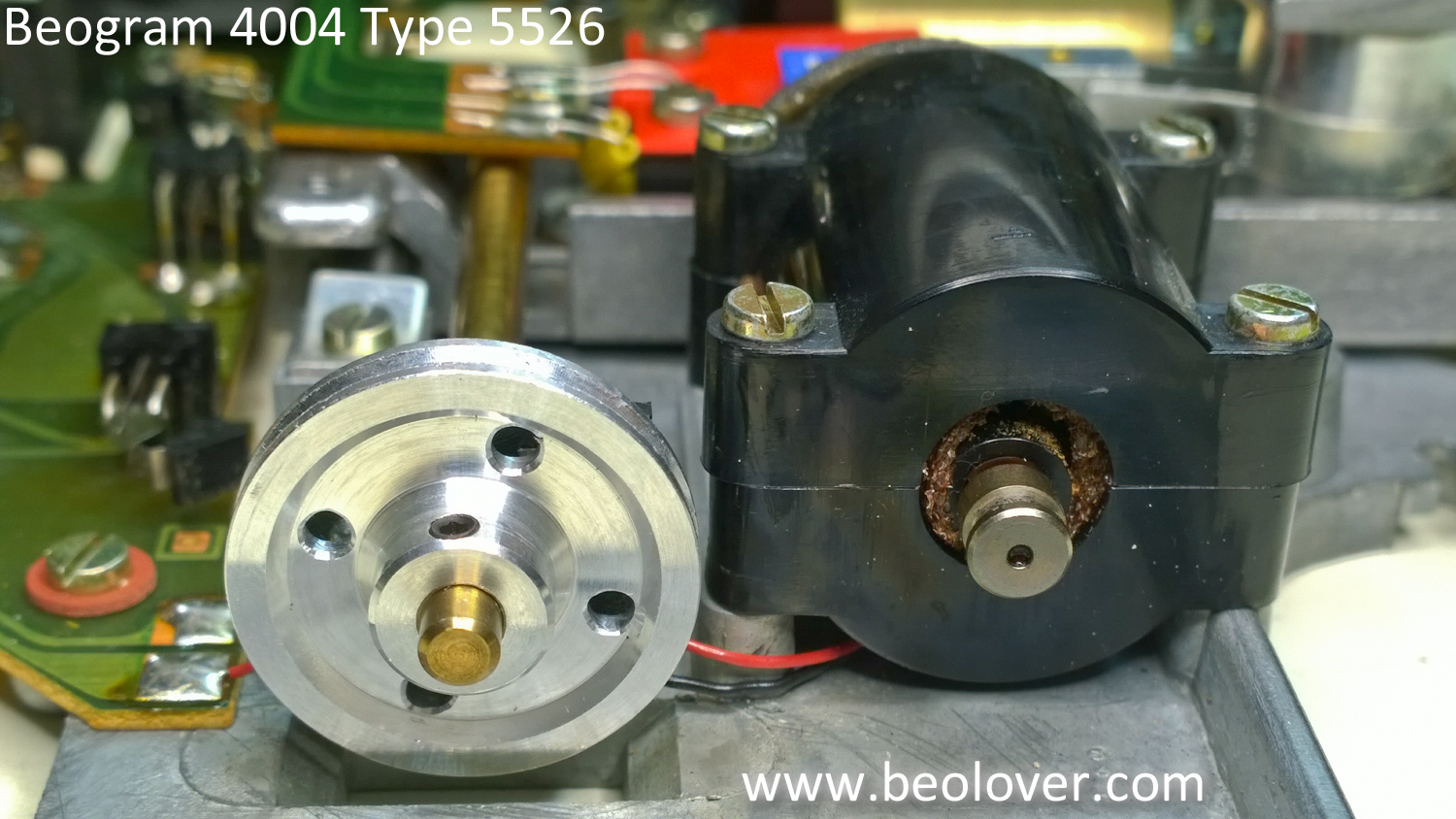
This is the point in the restoration where I also replace the tangential drive pulley. This picture shows the pulley options.  I like to replace these Beogram 400x drive pulleys with aluminum replacements from Nick (contact us if you want to get in touch with him).

The aluminum pulley on the left is Nick's original replacement (version 1). The black plastic pulley on the right is the original Beogram 4004 pulley. The pulley I am currently going with is Nick's Version 2 aluminum pulley (the one in the center of the picture). It is a nicer reproduction of the original pulley and is lighter weight than the Version 1 pulley. The indention of the middle area of the pulley also prevents accidental contact with the drive screw mounting bracket screws. A really super nice upgrade.


Here is the drive screw re-assembled with the new pulley.


I will go ahead and note it here that the tangential drive motor on this unit seems a little loose in its housing. I will look at that more closely when I get the Beogram put back together for testing. If I have to I will change out that motor.

Next I put the arm lowering parts back in place. The solenoid plunger is where it should be now.


I made one more electrical change on this Beogram tangential drive assembly while I had it out of the box. Like the recent Beogram 4002 restoration I changed out the old light source for the arm position sensor. The new LED light source will insure there won't be any problems with the old light source failing later. I also took the opportunity to clean the contacts of the tangential arm position switches (shown by the red arrows).


That pretty much does it for the tangential drive electrical restorations. All that I need to do before re-assembling these parts for testing is to align and balance the tonearm.