Featured Post

Beolover SyncDrive: DC Platter Motor Replacement for Beogram 4002 and 4004 (Type 551x and 552x)

Late Beogram 4002 and the 4004 (Types 551x and 552x), which have DC platter motors instead of the earlier synchronous AC motors usually suff...

Showing posts with label switch contacts. Show all posts

Sunday, April 3, 2022

Beomaster 4400 Type 2419: Continuing the Reassembly of the front panel switches

Continuing on from the previous post with the reassembly of the Beomaster 4400 front panel switches, I will also continue showing the differences in the switch panel components between early serial number units and later serial number units.

I did look up the B&O service manual addendum on the change with the switch panel.
According to that documentation the "early serial number" switch assemblies are for Beomaster 4400 serial numbers prior to SN 1524001.  Units with serial numbers 1524001 and on have the new switch assemblies.

That bears out on the Beomaster 4400 units I have seen.  The serial number for the Beomaster 4400 of this project is 1510043.

Here are some photos of the Beomaster 4400 front panel for both versions side by side.

From the front the difference is in the way the slider controls mount to the front panel.
The later serial number panel mounted the controls with screws from the front while the early serial number panel used metal spring clips. For that reason the early serial number front panels included a narrow mounting bracket for the slider controls to rest on.
The metal button panel frame that the switch assembly mounts to also changed due to the different style of switch actuators.


This picture shows the type of slider controls the Beomaster 4400 uses for the early serial number and later serial number units.


On two the circuit boards and wiring.
Both types of front panels have a small LED glued in place for the Stereo Indicator.
It is difficult to detach that LED assembly when disassembling the front panel so I started cutting the two wires that connect to the LED assembly.  When reassembling the panel I install a small 2-pin connector for the cut wires. That makes it a little easier in servicing the front panel.


The switch assembly is mounted to the front panel on a metal, button panel frame. 
It is secured with two screws.
The important thing here is to make sure all of the plastic switch actuators are pressed against their respective push buttons.


Now that the switch assembly is secured onto the front panel it is a good idea to double-check the mechanical operation of the switches again.


While I was working on the front panel assembly I took a little detour to replace the two 10,000uF electrolytic capacitors for the ±35 VDC output amplifier rails.  These are the two capacitors that are mounted on a bracket just to the side of PCB 5.


I also took a little time to install the two 100Ω trimmer resistors for the no-load current adjustment of the output amplifier. On those two trimmers I always go with multi-turn trimmers as they are easier to fine tune.

Here is the left channel trimmer.


Here is the right channel trimmer.


Returning to the reassembly of the front panel I decided to prepare the new incandescent lamps in the front panel wire harness.

Three of the five original lamps still worked but since I have to replace two I am going ahead and replacing all five with proper lamps from Martin's Beoparts store.

Here are the original lamps removed.


Here are the new lamps installed.


The next step of the front panel reassembly is to re-attach the circuit boards that mount to the switch assembly.  They are how the switches electrically connect to the Beomaster.

First is the PCB 6, 2-piece board.  
It has a normal, rigid PCB part and a flexible part to connect to the FM tuner preset dials.


The next PCB to attach to the switch assembly is PCB 9.


Here is a picture of the circuit boards reattached to the switch panel.


The front panel reassembly has gone smoothly so far.  
It is at the point where the wire harnesses get reattached.
In some cases that just means plugging in some connectors but unfortunately for me it also means quite a few loose wires that do not have a connector.  
That is the reason you have to take a lot of photos during the de-soldering of those wires when the front panel is being disassembled. 
I have those of course and my task for next time is to gather all of that information and carefully solder all of the individual, loose wires back in place.

Tuesday, March 29, 2022

Beomaster 4400 Type 2419: Reassembly of the front panel switches

The front panel switches are finally reassembled into the switch rack of this Beomaster 4400.
The switch contacts are clean and coated with Deoxit D100L contact conditioner. 


Reassembly of all the small contacts isn't too difficult but does require patience and tweezers.
You need to take care (and precautions) to keep the small contacts from jumping off the work table and into oblivion.  I made it through the reassembly without losing any.

I started with the far left switch, Speaker 1 Switch.  It only has two sets of the small spring contacts.


Once the fixed contacts are installed there are four metal tabs that must be carefully bent to secure the contact board to the switch actuator (white plastic part).


As I will show later, this early serial number Beomaster 4400 switch assembly is much easier to work with regarding the metal tabs.

Continuing on I inserted all of the spring contacts into the proper slots.
This photo shows my technique of using some good tweezers to angle in the spring contact pairs.


Here are all of the switch contacts in their proper slots prior to installing the top, fixed contact pieces.
Note that some switches have two sets of spring contacts, some have three sets and three switches have four sets of spring contacts.

I have labeled the switch functions in the photos.


Here is a repeat of the above sequence of switch photos with the top contact assemblies installed.
One other thing to note...The power (Off) switch assembly is sealed with plastic rivets.  I decided not to mess with that switch by attempting to disassemble it down to the contacts at this time.


Tip: The fixed contact top assemblies must be carefully slid into place. You have to make sure the fixed contacts align with the slits between the spring contacts. If you go too fast you risk a metal part not aligning and bending a spring contact where its shape deforms.  Not a good situation.

Before continuing on with any more front panel assembly this is a good time to test the operation of the switches.

While I have the switch assembly in this state I put a switch assembly from a later serial number Beomaster 4400 next to it in order to show some pretty major differences.

The switch assembly (and switch parts) are not interchangeable between these switch panels.
The switch assembly on the early serial number Beomaster 4400 units are more closely related to the Beomaster 4000 and Beomaster 3000 receivers that preceded it.

The switch assembly and switch parts of the late serial number Beomaster 4400 units is a different design as you can see in the next two photos.

Looking at just the AFC ST Switch there are some easy to spot differences.
The actuators are different (metal instead of plastic).
The AFC ST Switch went from two sets of spring contacts to four sets.
The spring contacts are shaped different.
The late serial number switch assembly has a plastic insert holder for the sets of spring contacts.
The metal tabs for the top, fixed contact part of the switch are much smaller on the newer switch assembly.
That is really a disappointment. There is no room for error and it is extremely easy to damage the newer tabs beyond repair. 
I haven't found a method of dealing with those new, tiny tabs that I am confident with.
My smallest and best pliers do not do a good enough job.


The PCB 6 board that the switch assembly solders to is different.


For this early serial number Beomaster 4400 project I will resume the front panel assembly and plan on having it back together in the next post.

Monday, March 28, 2022

Beomaster 4400 Type 2419: Cleaning & Polishing the 268 switch contacts

In a previous post for this Beomaster 4400 restoration project I mentioned disassembling the switches to clean and polish the switch contacts.

It took a while but I finally got all 268 front panel switch contacts completed.
I did take a little bit of a detour during the task to do some remodeling of the workshop but that is a different story.

With a much improved workspace the switch contacts are now polished and ready for reassembly.

Here is a picture of the start of the work with the switches all disassembled.


This photo shows a couple of the switch assemblies side by side.
The set on the left has not been cleaned and polished.  The set on the right has.


Here is a photo of the complete set of switch contacts after cleaning and polishing them all.


Here is a closer view.


This level of Beomaster 4400 disassembly for cleaning is not always necessary.
If the front switch panel is performing correctly then simply spraying some Deoxit contact cleaner/conditioner into the switch housings (and exercising the switches about 50 times) is enough.

However, I have run into one case where a Beomaster 4400 switch assembly operated correctly for periods of time but then had problems (making contact).

Also...on this Beomaster 4400 project there was a problem with the Off switch not functioning.
So in this type of scenario, since it is already a big task to disassemble the switches in order to fix the Off switch, I decided I might as well take advantage of the open switch assembly and clean all of the contacts manually.

The next post will reassemble the switch assembly and prepare the Beomaster 4400 for powering on.

Monday, April 20, 2020

Beomaster 4400 Type 2419: Power On/Off Switch Woes

This Beomaster 4400 would be ready to resume testing again if only its power on/off switch would work properly.

If you remember the original power on/off switch caught fire and had badly burned contacts.

For the replacement power on/off switch I pulled a switch out of a spare parts, donor Beomaster 4400 unit. I had no idea of the condition of that unit and when I opened up the power switch it had some pitting but overall wasn't too bad. A little cleaning and it was ready to install and that should have been the end of it.  It wasn't of course :-).

While the replacement switch initially measure a nice 0.1 ohm to 0.2 ohm "On" resistance when it was installed and in use the switch became unreliable and needed some fiddling with the buttons to get the Beomaster to turn on. Something mechanical was not right.

My next plan was to grab a second replacement, donor power on/off switch from another parts unit. The switch didn't look too bad until I checked it out with an ohmmeter. Off measured fine but the "On" resistance jumped around in the 100 to 300 ohm range. Not a good reading.

So I opened up this third Beomaster 4400 power on/off switch and it was about as badly burned as the first one.

Here is the third switch (second replacement candidate).


Very ugly and very disappointing to say the least.

I don't even want to try to clean that up.

When I reopened my first replacement candidate switch its contacts still looked pretty good but the switch contacts had shifted position so good contact was not being made. That explained the mechanical inconsistency.

I had to stop and think about my options.  I could really go for a nice 3D printed replacement switch about now.  Unfortunately that doesn't exist (yet).

My best chance here is to select my best contacts and my best plastic housing components to put together a solid working power on/off switch.

I think my first replacement switch attempt failed because I soldered too many connections to the outer terminals.  They heated up and then shifted internally which caused the poor switching performance.

This time I will make sure to make the other connections away from the switch and just attach two wires to the switch contacts. In addition I will use some heat protection while the contacts are soldered.

Here are my collection of Beomaster 4400 power on/off switch contacts.


If I turn the best set of contacts around I will have fresh new surfaces to mate for the power on switching. I will clean up the switch housing on the lower right to use in the new switch assembly attempt as it is the most structurally sound.


Another problem involving the power on/off switch that I will have to solve is remounting the switch on the switching assembly.  There are damaged mounting tabs so I will have to construct something to secure the switch when I mount it.

Wednesday, July 19, 2017

Beogram 4004 Type 5526: Tangential Drive Work

The last post left off with the fixed arm sensor lamp being replaced with the custom Beolover lamp assembly. To go along with that (reversible) modification a change on the main board is also required.
Per Beolover's explanation here and his repair technique here I temporarily installed a 2M ohm trimmer resistor on the trace side of the main board so I can easily make the initial adjustment. I will do that adjustment later when I get ready to test these current changes.

This picture shows the original 1M ohm resistor (R26) that will get replaced.


Here is the replacement 2M ohm trimmer installed in its temporary location until the adjustment procedure can be made.


As I moved on to install the Beolover replacement module for the tangential tracking I noticed something wrong with the arm lowering solenoid. I didn't notice the problem when I was busy working on the damper but here in this picture you can clearly see that the solenoid is missing its plunger.

I found the plunger and re-attached it to the lever using a dab of lock-tight.


To fix the solenoid I removed all of the arm damping components again and will leave them out while I work on the rest of the tangential arm assembly. Having the chassis clear of those components will make working in there a little easier.

Here is the removal of the original tracking sensor assembly. The Beolover replacement part will fit right in place of the original light source housing and the original parts will be saved in case someone wants to revert back to them in the future.


That looks great. Now on to the drive screw cleaning and lubricating.
The drive screw bearing nut and housing always gets dirty over time. This one is no exception. There are even some specs of debris from the disintegrated chassis lock down bushings. Those pieces continue to show up.


I completely remove the drive screw and parts for cleaning and re-lubricating.


I am satisfied the drive screw parts are clean and ready for re-assembly.
This is the point in the restoration where I also replace the tangential drive pulley. This picture shows the pulley options.  I like to replace these Beogram 400x drive pulleys with aluminum replacements from Nick (contact us if you want to get in touch with him).

The aluminum pulley on the left is Nick's original replacement (version 1). The black plastic pulley on the right is the original Beogram 4004 pulley. The pulley I am currently going with is Nick's Version 2 aluminum pulley (the one in the center of the picture). It is a nicer reproduction of the original pulley and is lighter weight than the Version 1 pulley. The indention of the middle area of the pulley also prevents accidental contact with the drive screw mounting bracket screws. A really super nice upgrade.


Here is the drive screw re-assembled with the new pulley.


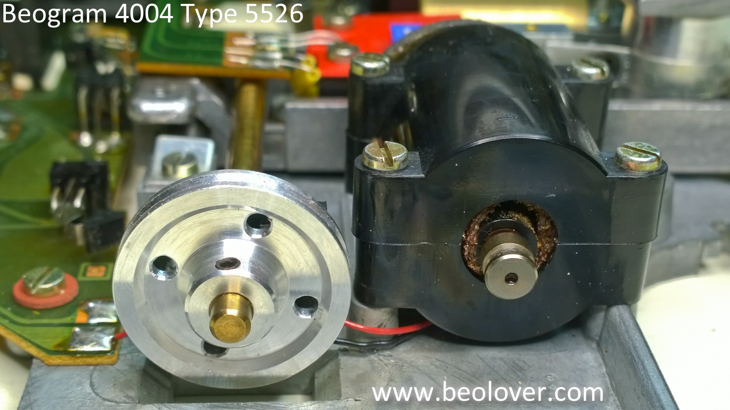
I will go ahead and note it here that the tangential drive motor on this unit seems a little loose in its housing. I will look at that more closely when I get the Beogram put back together for testing. If I have to I will change out that motor.

Next I put the arm lowering parts back in place. The solenoid plunger is where it should be now.


I made one more electrical change on this Beogram tangential drive assembly while I had it out of the box. Like the recent Beogram 4002 restoration I changed out the old light source for the arm position sensor. The new LED light source will insure there won't be any problems with the old light source failing later. I also took the opportunity to clean the contacts of the tangential arm position switches (shown by the red arrows).


That pretty much does it for the tangential drive electrical restorations. All that I need to do before re-assembling these parts for testing is to align and balance the tonearm.