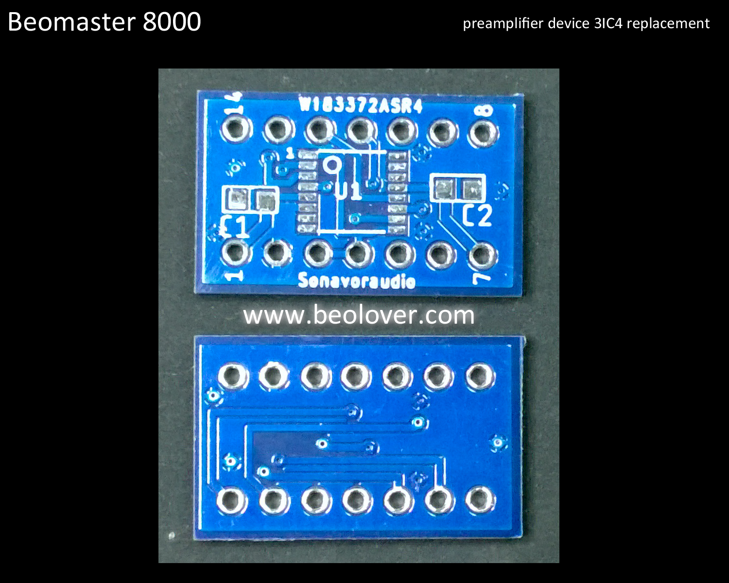
To go together with the previous Beomaster 8000 replacement part for the preamplifier source switching device (AD 10/278 - 3IC102/3IC202), I have completed the replacement part for the other switching device on the preamplifier board.
The second source switching device is 3IC4. The original device is an AD 10/192 multiplexer and like the other switching ICs, this device is no longer available.
Here is the schematic diagram again that shows the two source switching type devices in the Beomaster 8000 preamplifier.
The 3IC102 and 3IC202 replacements were completed earlier. Now it is time for the 3IC4 device.
Like the the other replacement I first built a prototype and tested it in my Beomaster 8000 workshop test unit. It worked as good as I expected so I had an adapter board made.
Here is the replacement switching device on the new adapter board next to my prototype.
...and here is the first replacement device unit installed in the Beomaster 8000 preamplifier.
The Beomaster 8000 preamplifier works great with the source multiplexing devices replacements.
Now to the fun listening test phase.
Featured Post
Beolover SyncDrive: DC Platter Motor Replacement for Beogram 4002 and 4004 (Type 551x and 552x)
Late Beogram 4002 and the 4004 (Types 551x and 552x), which have DC platter motors instead of the earlier synchronous AC motors usually suff...
Showing posts with label bench test. Show all posts
Monday, July 8, 2019
Beomaster 8000 - Workbench Unit - Testing a replacement device for the AD 10/192 Multiplex Switch on the preamplifier board
Labels:
2019SVRBM8000-01,
3IC4,
AD 10/192,
analog switch,
Bang & Olufsen,
bench test,
Beomaster 8000,
preamplifier,
replacement part,
restoration,
sonavoraudio,
test unit,
testing,
trouble-shooting,
workbench
Thursday, June 20, 2019
Beomaster 8000 - Workbench Unit - Testing a replacement device for the AD 10/278 Multiplex Switch on the preamplifier board
One of my first projects utilizing my new, dedicated workshop Beomaster 8000 unit is to test out a replacement device I created for the BM8000 preamplifier board's input source switching ICs - IC102 and IC202. They are the no-longer-available AD 10/278 multiplexer device.
Here is the circuit diagram of the Beomaster 8000 preamplifier source select switching.
As you can see there are actually two types of analog switch devices. 3IC102 and 3IC202 are AD 10/278 devices for selecting between FM, Phono and Tape 2 left and right channel sources. 3IC4 is an AD 10/192 device that selects between Tape 1 or whichever source is selected with 3IC102 and 3IC202. Selection control of course comes from the Beomaster 8000 Microcomputer board (via 3P14).
Once in a while AD 10/192 devices can be found for sale but I have never been able to find NOS AD 10/278 ICs. Concerned that a failed AD 10/278 can bring an entire Beomaster 8000 restoration project to a grinding halt I decided to look into making a modern replacement. I was also motivated by reports from some Beomaster 8000 owners who complained about crosstalk between the FM source and Phono source. I felt that if that were to occur it would most likely be due to a problem with the 3IC102 and 3IC202 analog switch. However, I must confess, after quite a number of Beomaster 8000 restorations I have yet to experience any crosstalk problems between input sources myself. Still...another reason to create a replacement device.
To follow Beolover's lead in creating replacement parts for the various Bang & Olufsen restorations we have done, a key goal is that the new part be a direct plug and play replacement. No modifications to the Bang & Olufsen component to use it. So in the case of the AD 10/278 replacement I needed a design that would result in the old 3IC102 and/or 3IC202 desoldered for removal...and the replacement inserted and soldered into place.
I believe I have accomplished that with a custom adapter board and a modern three channel SMD multiplexer device designed for audio switching.
I started with a prototype using the replacement device in a standard DIP package layout and a breadboard circuit where I could test inputting test signals and selecting channels just like the Beomaster 8000. Once I had that perfected I sent my design off to have my adapter boards made.
Here is my breadboard tester for the AD 10/278 with the various test devices.
Confirming that the prototype and first replacement units function just like the original devices I installed the first two replacement units in a Beomaster 8000 preamplifier board.
Then the preamp board into my Beomaster workshop unit.
The results are as good as I expected. The source selection works just as it should and I cannot hear any crosstalk between selected sources.
I need to run some additional testing of course but I am thrilled with these initial results.
Here is the circuit diagram of the Beomaster 8000 preamplifier source select switching.
As you can see there are actually two types of analog switch devices. 3IC102 and 3IC202 are AD 10/278 devices for selecting between FM, Phono and Tape 2 left and right channel sources. 3IC4 is an AD 10/192 device that selects between Tape 1 or whichever source is selected with 3IC102 and 3IC202. Selection control of course comes from the Beomaster 8000 Microcomputer board (via 3P14).
Once in a while AD 10/192 devices can be found for sale but I have never been able to find NOS AD 10/278 ICs. Concerned that a failed AD 10/278 can bring an entire Beomaster 8000 restoration project to a grinding halt I decided to look into making a modern replacement. I was also motivated by reports from some Beomaster 8000 owners who complained about crosstalk between the FM source and Phono source. I felt that if that were to occur it would most likely be due to a problem with the 3IC102 and 3IC202 analog switch. However, I must confess, after quite a number of Beomaster 8000 restorations I have yet to experience any crosstalk problems between input sources myself. Still...another reason to create a replacement device.
To follow Beolover's lead in creating replacement parts for the various Bang & Olufsen restorations we have done, a key goal is that the new part be a direct plug and play replacement. No modifications to the Bang & Olufsen component to use it. So in the case of the AD 10/278 replacement I needed a design that would result in the old 3IC102 and/or 3IC202 desoldered for removal...and the replacement inserted and soldered into place.
I believe I have accomplished that with a custom adapter board and a modern three channel SMD multiplexer device designed for audio switching.
I started with a prototype using the replacement device in a standard DIP package layout and a breadboard circuit where I could test inputting test signals and selecting channels just like the Beomaster 8000. Once I had that perfected I sent my design off to have my adapter boards made.
Here is my breadboard tester for the AD 10/278 with the various test devices.
Confirming that the prototype and first replacement units function just like the original devices I installed the first two replacement units in a Beomaster 8000 preamplifier board.
Then the preamp board into my Beomaster workshop unit.
The results are as good as I expected. The source selection works just as it should and I cannot hear any crosstalk between selected sources.
I need to run some additional testing of course but I am thrilled with these initial results.
Labels:
2019SVRBM8000-01,
3IC102,
3IC202,
AD 10/278,
analog switch,
Bang & Olufsen,
bench test,
Beomaster 8000,
preamplifier,
replacement part,
restoration,
sonavoraudio,
test unit,
testing,
trouble-shooting,
workbench
Monday, June 17, 2019
Beomaster 8000 - Workbench Unit
After restoring quite a few Beomaster 8000 receiver units I have developed several bench testing aids. I have some jigs for testing the rebuilding of displays and I have a test setup for testing the Beomaster 8000 output amplifier assemblies.
During various Beomaster 8000 projects I have also restored a number of Beomaster 8000 spare circuit boards. To checkout my spares and to aid in Beomaster 8000 diagnostic trouble-shooting I have been wanting to built up a dedicated, workbench unit. This would be a test unit I could swap boards in and out of easily for testing purposes. I had a couple of spare Beomaster 8000 chassis laying around so the time finally arrived to implement this workbench Beomaster 8000 unit.
Here is the completed workbench Beomaster 8000. It will remain in its service position and never be completely reassembled. I want it always available for testing.
Even the startup circuit is left open for measurements and to test the startup relays. This unit has two brand new 7RL1 and 7RL2 relay devices installed. It also has replacement 7R1 and 7R2 5.6Ω current limiting resistors.
I also replaced the four ±55VDC power supply reservoir capacitors with the Beolover Beomaster 8000 reservoir capacitor kit.
A bonus side benefit of having this workbench Beomaster 8000 is that I can also listen to it while working on various Beolover Blog projects :-)
In the upcoming weeks I will be doing some Beomaster 8000 board restoration and testing. I will utilize this test unit for those tasks and detail the work here on the Beolover Blog.
During various Beomaster 8000 projects I have also restored a number of Beomaster 8000 spare circuit boards. To checkout my spares and to aid in Beomaster 8000 diagnostic trouble-shooting I have been wanting to built up a dedicated, workbench unit. This would be a test unit I could swap boards in and out of easily for testing purposes. I had a couple of spare Beomaster 8000 chassis laying around so the time finally arrived to implement this workbench Beomaster 8000 unit.
Here is the completed workbench Beomaster 8000. It will remain in its service position and never be completely reassembled. I want it always available for testing.
Even the startup circuit is left open for measurements and to test the startup relays. This unit has two brand new 7RL1 and 7RL2 relay devices installed. It also has replacement 7R1 and 7R2 5.6Ω current limiting resistors.
I also replaced the four ±55VDC power supply reservoir capacitors with the Beolover Beomaster 8000 reservoir capacitor kit.
A bonus side benefit of having this workbench Beomaster 8000 is that I can also listen to it while working on various Beolover Blog projects :-)
In the upcoming weeks I will be doing some Beomaster 8000 board restoration and testing. I will utilize this test unit for those tasks and detail the work here on the Beolover Blog.
Tuesday, March 19, 2019
Beomaster 8000: Output Amplifier Solo Project
A Bang & Olufsen enthusiast and Beomaster 8000 DIY restorer from Canada sent me one of his Beomaster output amplifier assemblies to sort out. On his recapping and restoration project he was having trouble getting this output amplifier to adjust correctly per the service manual.
Capacitors 5C202 and 5C215 each had a broken solder pad so I routed their connection paths using the purple colored wire shown in the picture below.
In this case I reached 110mA when there was only +6VDC on the +15V supply. The voltage across the two emitter resistors was 24mV.
I turned the no-load trimmer resistor so the current draw on the ±55V supplies dropped back down to around 60mA. Then I increased the +15V supply some more. That iteration continued until I reached +15VDC on the +15V supply and the current draw on the ±55V rail supplies was 100mA to 110mA.
Initially the DC voltage was a little high, about 0.8mV, so I used the DC offset 100Ω trimmer resistor to dial in around 0.1mVDC of offset. The service manual calls for less that 5mV so this is quite satisfactory.
There are two of these output amplifier assemblies in a Beomaster 8000. One for each channel. Only one of the amplifier channels is giving him a problem so he sent the bad actor to me.
Here is the output amplifier assembly as I received it. The heatsink components all look good but the amplifier board has problems with failing component solder pads. They have likely been over-heated and have released from the board. The owner attempted to repair them but I found problems with those.
The electrolytic capacitors have already been replaced as well as the two 100Ω trimmer resistors for the no-load current and DC offset adjustments.
I prefer multi-turn trimmers for this board though so I will replace the installed single turn trimmers. I will also de-solder the components associated with the failed solder pads and make repairs to those.
Here is a closer look at the trace side of the board with the problems.
The worst section of the damage is the broken solder pad for the positive lead of capacitor 5C211 (100uF, 16V). Examining the traces for that capacitor I see that it can be remounted across two of the solder pads for the 5R200 (DC Offset) trimmer...which I am replacing anyway.
I installed a smaller, radial type electrolytic capacitor for 5C211 and it fit very nicely.
Here are pictures of the reworked amplifier board.
Capacitors 5C202 and 5C215 each had a broken solder pad so I routed their connection paths using the purple colored wire shown in the picture below.
This board is ready for bench testing where I will make the no-load current adjustment and the DC offset adjustment.
The first step of bench testing is to reset and check that my bench DC power supplies (that will provide the ±55VDC rail voltages) are correctly set to a current limit of 0.15A. That will protect the board (and me).
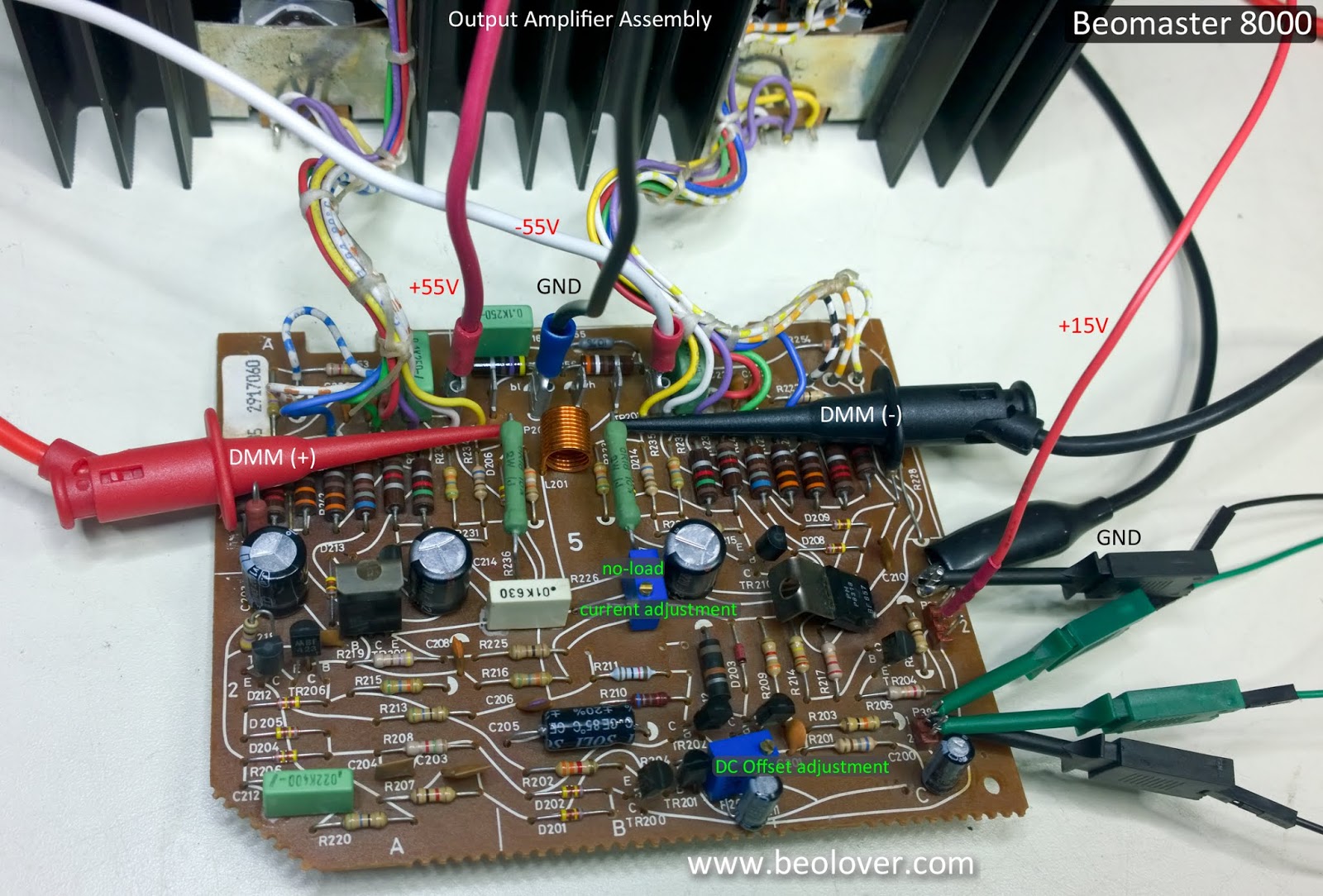
After the current limits have been set on the power supplies I can connect up the power and ground wires to the output amplifier board for testing.
Next I apply the ±55VDC rail voltages. The output amplifier will not fully be on until I the +15V supply is applied to the amplifier. Here is what the power supplies should look like at this point.
This is a great sign. So far so good. The output amplifier is essentially in standby mode and only drawing 30mA from each rail.
Now I turn the amplifier on by dialing up the +15V supply. I do this a little bit at a time. I don't jump right to +15VDC. Because the no-load current trimmer has been replaced, I don't know where the initial setting needs to be.
As I start applying voltage to the +15V supply line the current draw on the ±55V supplies starts to go up. I don't want that current to go higher than 100mA to 110mA (on each supply). Of course I have the current limit on the supplies set to 0.15A as a backup so no real worries.
In this case I reached 110mA when there was only +6VDC on the +15V supply. The voltage across the two emitter resistors was 24mV.
I turned the no-load trimmer resistor so the current draw on the ±55V supplies dropped back down to around 60mA. Then I increased the +15V supply some more. That iteration continued until I reached +15VDC on the +15V supply and the current draw on the ±55V rail supplies was 100mA to 110mA.
I knew what values to expect here from having bench tested a lot of these amplifiers now.
The DC voltage across the emitter resistors was now very close to the desired 18mV per the service manual. I adjusted the no-load trimmer at this point to get as close to 18mV across the emitter resistors as I could.
One service manual adjustment down and one to go.
The next adjustment is the DC offset.
For the DC offset adjustment I turned off the bench power supplies and I connected up one of my 8Ω dummy speaker loads. Then I reapplied the ±55VDC rail voltages and the +15V supply voltage.
The output amplifier was on again and I could measure the DC voltage across the 8Ω speaker load.
Initially the DC voltage was a little high, about 0.8mV, so I used the DC offset 100Ω trimmer resistor to dial in around 0.1mVDC of offset. The service manual calls for less that 5mV so this is quite satisfactory.
This output amplifier assembly is ready to rejoin its Beomaster 8000 components and will hopefully be playing music again soon.
Sunday, April 8, 2018
Beomaster 8000 - Output Amplifier Bench Testing Review
I felt like the left and right channel output amplifier boards were in good shape after the restoration and I was successful in presetting the no-load current adjustment during the bench testing.
However, I was left disappointed that I wasn't able to preset the DC offset adjustment of the boards during my bench test. I tried doing the DC offset adjustment but when I connected a dummy 8Ω speaker load for the adjustment procedure the current draw on the ±55V supplies was not balanced. There was quite a bit more current on the -55V supply than on the +55V supply. To go along with that I could only adjust the DC offset to around -380mV across the speaker load.
Here is a picture of the bench power supply load when attempting the DC offset adjustment.
The current draw imbalance occurs as soon as the 8Ω speaker load is applied. Even when the output amplifier is in the off state (+15V supply at zero volts). Turning the output amplifier on (+15V supply above +14V) raises the current draw on the ±55V supplies but there is still a 50mA difference.
Why was that? The DC offset adjustment procedure calls for the speaker connection to be on and the volume level to be at zero.
I have the 8Ω speaker load connection and I have nothing applied to the audio input connector on the output amplifier board.
Here is the schematic marked up with my test connections.
You can see that I have the audio input pins shown as having the option of being open or shorted together. I first thought that shorting them together would solve the problem because that should be the same as zero volts per the service manual instructions.
That was not correct. My next thoughts were that this board must have some fault preventing the DC offset adjustment. When I tried three more output amplifier assemblies I got the exact same result on all three. No way that I have four faulty boards. Especially with the exact same fault.
Here is a picture of my fourth output amplifier assembly DC offset adjustment test.
This meant that my stand alone bench test is not correctly representing what the board sees when it is properly installed in a Beomaster.
At this point I turned to Martin Olsen for advice. I get a lot of parts from Martin and he is an experienced Bang & Olufsen tech who has provided me with some great information on repairs over the years.
After thinking about the problem of attempting this stand alone bench test procedure Martin suggested that to be accurate in my audio input setup the two input pins should be grounded.
That was exactly the problem!
From the schematic picture above you can see how I thought shorting the two audio input pins would ground the signal so I would have zero volts. That turns out to not be sufficient for this stand alone board bench test. Looking at the output amplifier trace side and the service manual schematic again I can see that the audio input low signal is shown to be going to signal ground. Not board ground. There is no real signal with the output amplifier sitting on the bench by itself. Signal ground is really just undefined in this test environment.
Following the board traces that P39-1 connects directly to I can verify all of the signal ground connections indicated on the schematic. I have marked them up on my schematic below as the green, dotted lines to clarify those connections.
Here is the clarified schematic and my new test setup.
So connecting the audio inputs (P39-1 and P39-2) together is pretty much the same as leaving them open on this stand alone bench test. That is what I observed in attempting to perform the DC offset with the 8Ω speaker load. With the board being stand alone on the bench it requires P39-1 and 2 connected to each other and to board ground so there is a true reference to the return in this environment. That sets the input at a defined, 0 VDC level and the amplifier stable for the DC offset adjustment.
Marking up the Beomaster relevant schematic parts that show the output amplifier board connected to the rest of the Beomaster I can see the required ground connection I missed. The audio signal ground between the Filter & Tone Controls board gets routed to chassis ground. Chassis ground connects to the output amplifier board ground post, P37, which connects to the main ground.
Connecting up output board P37 ground post to the P39 input pins, I immediately noticed the result on the bench power supplies.
The current draw on the ±55V supplies is now close to the same. This is what I see with good output amplifier boards in a Beomaster 8000 receiver. The DC offset adjustment is now able to dial in to the expected 0 ± 0.5mV range.
Here are some pictures of the output amplifier board and the test setup.
Here are a few summary notes regarding the stand alone bench testing of the Beomaster 8000 output amplifier board.
1. Start with the audio input connector pins shorted to the ground pin on the output amplifier board.
2. Have the speaker load disconnected
3. You need two DC power supplies capable of +55 VDC and have current limiting protection. I set mine to stop at 150mA. This will prevent a bad situation should the output amplifier have a short somewhere.
4. You need a third DC power supply capable of +15 VDC to enable the output amplifier to turn on.
5. Dial up the ±55 VDC supplies first. Increase their voltage slowly from 0V to 55V. Observe their current draw as the voltage is increased. When new parts (including trimmer resistors) have been installed on the output amplifier board it is very common for the supply current to go above 130mA way before 55 volts is reached. When this happens you must dial down the supply current by adjusting the no-load current trimmer on the output amplifier board. Use that trimmer to keep the supply current around 30mA until ±55 volts are reached by the supplies.
6. Turn the output amplifier on by slowly increasing the +15 VDC supply from 0V to +15V. Observe the current draw on the ±55V supplies while doing this. The ±55V current should not go above 120mA. The typical current values I have seen are 100mA to 110mA.
7. With the output amplifier powered up and on, adjust the no-load current to the desired 18mV value across the emitter resistors.
8. Power down the +15V supply to turn the output amplifier off.
9. Connect the speaker load
10. Reapply the +15V to turn the output amplifier back on and observe that the ±55V supply current is in the 100mA to 110mA range.
11. Measure and adjust the DC offset trimmer to get 0±0.5mV across the speaker load.
That should do it. The output amplifier assembly is nicely checked out prior to installation. If there is a failed component on the board it should reveal itself during these tests and should be easier to trouble-shoot with this test setup.
However, I was left disappointed that I wasn't able to preset the DC offset adjustment of the boards during my bench test. I tried doing the DC offset adjustment but when I connected a dummy 8Ω speaker load for the adjustment procedure the current draw on the ±55V supplies was not balanced. There was quite a bit more current on the -55V supply than on the +55V supply. To go along with that I could only adjust the DC offset to around -380mV across the speaker load.
Here is a picture of the bench power supply load when attempting the DC offset adjustment.
The current draw imbalance occurs as soon as the 8Ω speaker load is applied. Even when the output amplifier is in the off state (+15V supply at zero volts). Turning the output amplifier on (+15V supply above +14V) raises the current draw on the ±55V supplies but there is still a 50mA difference.
Why was that? The DC offset adjustment procedure calls for the speaker connection to be on and the volume level to be at zero.
I have the 8Ω speaker load connection and I have nothing applied to the audio input connector on the output amplifier board.
Here is the schematic marked up with my test connections.
That was not correct. My next thoughts were that this board must have some fault preventing the DC offset adjustment. When I tried three more output amplifier assemblies I got the exact same result on all three. No way that I have four faulty boards. Especially with the exact same fault.
Here is a picture of my fourth output amplifier assembly DC offset adjustment test.
This meant that my stand alone bench test is not correctly representing what the board sees when it is properly installed in a Beomaster.
At this point I turned to Martin Olsen for advice. I get a lot of parts from Martin and he is an experienced Bang & Olufsen tech who has provided me with some great information on repairs over the years.
After thinking about the problem of attempting this stand alone bench test procedure Martin suggested that to be accurate in my audio input setup the two input pins should be grounded.
That was exactly the problem!
From the schematic picture above you can see how I thought shorting the two audio input pins would ground the signal so I would have zero volts. That turns out to not be sufficient for this stand alone board bench test. Looking at the output amplifier trace side and the service manual schematic again I can see that the audio input low signal is shown to be going to signal ground. Not board ground. There is no real signal with the output amplifier sitting on the bench by itself. Signal ground is really just undefined in this test environment.
Following the board traces that P39-1 connects directly to I can verify all of the signal ground connections indicated on the schematic. I have marked them up on my schematic below as the green, dotted lines to clarify those connections.
Here is the clarified schematic and my new test setup.
So connecting the audio inputs (P39-1 and P39-2) together is pretty much the same as leaving them open on this stand alone bench test. That is what I observed in attempting to perform the DC offset with the 8Ω speaker load. With the board being stand alone on the bench it requires P39-1 and 2 connected to each other and to board ground so there is a true reference to the return in this environment. That sets the input at a defined, 0 VDC level and the amplifier stable for the DC offset adjustment.
Marking up the Beomaster relevant schematic parts that show the output amplifier board connected to the rest of the Beomaster I can see the required ground connection I missed. The audio signal ground between the Filter & Tone Controls board gets routed to chassis ground. Chassis ground connects to the output amplifier board ground post, P37, which connects to the main ground.
Connecting up output board P37 ground post to the P39 input pins, I immediately noticed the result on the bench power supplies.
Here are some pictures of the output amplifier board and the test setup.
Here are a few summary notes regarding the stand alone bench testing of the Beomaster 8000 output amplifier board.
1. Start with the audio input connector pins shorted to the ground pin on the output amplifier board.
2. Have the speaker load disconnected
3. You need two DC power supplies capable of +55 VDC and have current limiting protection. I set mine to stop at 150mA. This will prevent a bad situation should the output amplifier have a short somewhere.
4. You need a third DC power supply capable of +15 VDC to enable the output amplifier to turn on.
5. Dial up the ±55 VDC supplies first. Increase their voltage slowly from 0V to 55V. Observe their current draw as the voltage is increased. When new parts (including trimmer resistors) have been installed on the output amplifier board it is very common for the supply current to go above 130mA way before 55 volts is reached. When this happens you must dial down the supply current by adjusting the no-load current trimmer on the output amplifier board. Use that trimmer to keep the supply current around 30mA until ±55 volts are reached by the supplies.
6. Turn the output amplifier on by slowly increasing the +15 VDC supply from 0V to +15V. Observe the current draw on the ±55V supplies while doing this. The ±55V current should not go above 120mA. The typical current values I have seen are 100mA to 110mA.
7. With the output amplifier powered up and on, adjust the no-load current to the desired 18mV value across the emitter resistors.
8. Power down the +15V supply to turn the output amplifier off.
9. Connect the speaker load
10. Reapply the +15V to turn the output amplifier back on and observe that the ±55V supply current is in the 100mA to 110mA range.
11. Measure and adjust the DC offset trimmer to get 0±0.5mV across the speaker load.
That should do it. The output amplifier assembly is nicely checked out prior to installation. If there is a failed component on the board it should reveal itself during these tests and should be easier to trouble-shoot with this test setup.
Subscribe to:
Posts (Atom)