Featured Post

Beolover SyncDrive: DC Platter Motor Replacement for Beogram 4002 and 4004 (Type 551x and 552x)

Late Beogram 4002 and the 4004 (Types 551x and 552x), which have DC platter motors instead of the earlier synchronous AC motors usually suff...

Showing posts with label balance. Show all posts

Wednesday, January 27, 2021

A Pair of Beomaster 1900 Receivers for Restoration: Installing New Lamps (Unit #1)

I replaced all of the indicator lamps in the Beomaster 1900 today.

For the Bass, Treble and Balance indicator lamps I change from the original incandescent type lamps to LED/resistor type lamp assemblies. The reason for that is the incandescent type lamps generate more heat and I can see from white spots on the red lamp lenses that the heat has had an effect.  The LED lamp assemblies will operate much cooler.

Here is the board with the original Bass, Treble and Balance lamps.  I was out of my LED replacement lamp assemblies so I built more than the three I needed for this project as I know I will be needing the extra assemblies soon.


Here are the new Bass, Treble and Balance LED lamp assemblies installed.
Polarity matters with LEDs so I marked where the positive lead has to go on the board.


For the remaining twelve indicator lamps I replaced the original incandescent lamps with new incandescent lamps that I source from Beoparts. They are the correct type and necessary in these indicators so that the underlying Beomaster 1900 circuits work as intended.

There are two lamps on the volume control board and ten lamps on the selected source and FM tuning indicator board.

Here is the before photo of the lamps. I can see that these are replacements that were probably installed when this Beomaster had its bridge rectifier for the 15 volt power supply replaced.


Here are the new lamps.  All uniform...all the same type.


Now this Beomaster is ready for reassembly then on to the power supply testing.


Tuesday, July 9, 2019

Beomaster 2400 Type 2902: Tone controls slider bridge repair

A common failure on the Beomaster 1900 and 2400 receivers is with the tone control slider assemblies. Each slider has a left and right channel contact that slide up and down together on a plastic bridge. The contacts are press fitted onto the bridge and held by a plastic post and bar. Over time the plastic bar breaks and the contact comes loose. That results in the slide control no longer working.

Martin Olsen on Beoworld makes replacement slider bridge kits specifically for the Beomaster 1900 and 2400 units. I have used his kit on all of my Beomaster 1900 restorations so far and will continue with this Beomaster 2400 unit. The replacement bridge parts have a beefier bar for the contacts to mount to than the original part.

Here are each of the three tone control sliders disassembled from the tone control board starting from left to right with the Bass slider first.


As you can see the Bass slider has the usual broken tab but it also has a problem where one of the contacts is missing.  I did not see it anywhere in the Beomaster cabinet so it is long gone.  Fortunately I have a spare.

Next is the Treble slider.


Both left and right channel contacts are present with the Treble slider but its slider bridge tabs are broken.

Last is the Balance slider.


The Balance slider has its slider bridge all intact.  I will still replace it along with the Bass and Treble sliders as this slider control is likely to break in the future.  Martin's repair kit comes with three replacement bridges so I will use all of them.

Besides replacing the slider bridge I clean the metal contacts and the rails.
The repair for all three slider control bridges is the same so I will just show one in detail here.


...and here are all three slider controls re-installed on the Beomaster 2400 Tone Control board.


Sunday, April 8, 2018

Beomaster 6000 (2702) restoration: checking, power-up and calibration

Everything is back into the chassis and now it's time to do a last check of all the wiring and powering up. It's important to make sure that no wires have been cracked, became loose or touching the chassis. This may seems obvious, but it is so important in a Beomaster 6000 quad because the space is so tight and most wiring is done with hard wires. I took all the time that I needed and found one wire broken off: a ground connection to the pre-amp.

So, a last peek inside before powering up......


I plugged the unit into my Variac transformer, gently raised the voltage to the required 230V and...........it fired up on all engines! I selected a FM station and listened to Katie Melua's version of Louis Armstrongs "What a wonderful world" ! And indeed it was......

That was a big relief. You never know what will happen after such a big restoration. But, off course, I had tested everything already before putting it al in the main chassis (check here). 

Some final calibration was now needed. I started with the power supply. I had done this before when restoring the power supply PCB, but under load settings may change. I found some slight variation. The +18V had now dropped to +17,85. Not to bad. And the -5V was now -5,1V (not sure why it went up). With the new trimmers in place, it was easy to recalibrate to the correct voltages.


On the same power supply PCB, a trimmer is located to balance the FM reception lights.

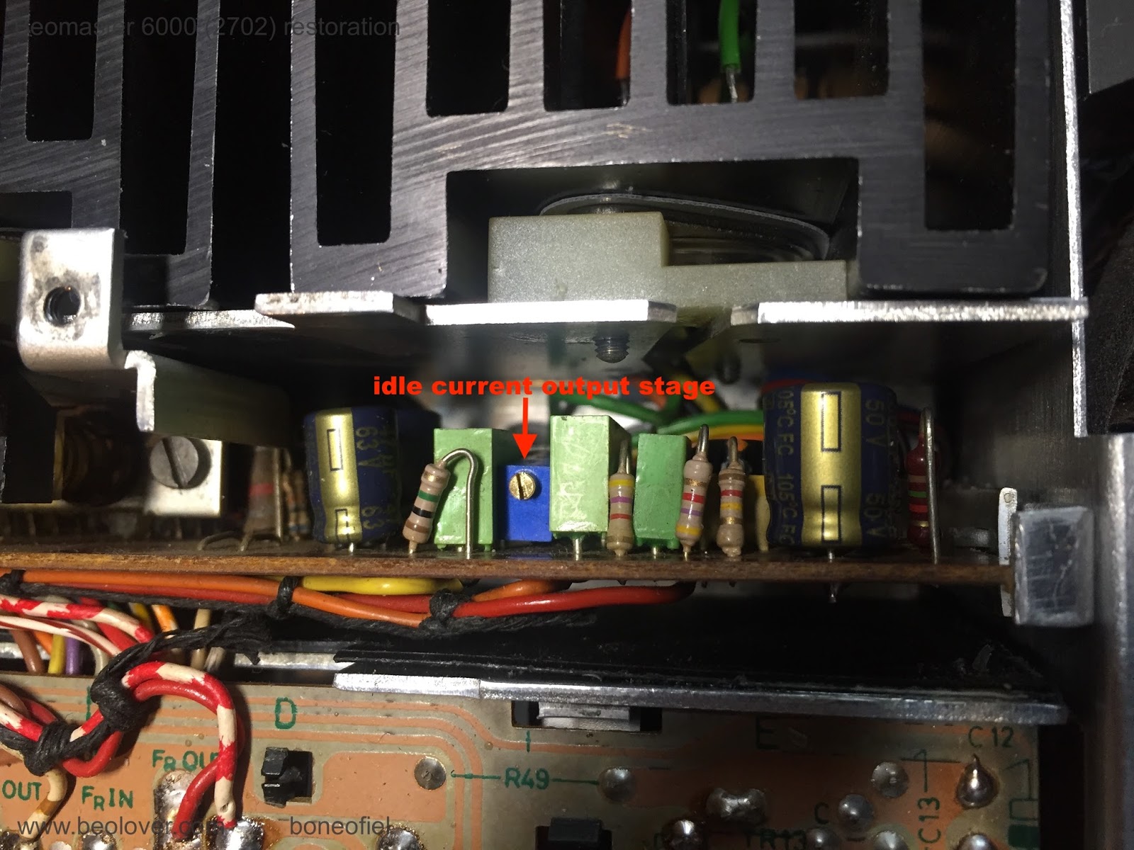
The idle (quiescent, bias or no-signal) current was already set before, but I checked it again by measuring the voltage drop over the 2 emitter transistors (0,12 ohm), in series, that are in each set of the Darlington output stages. The service manual describes to measure directly on one of the collector resistors on the PCB. They are very difficult (if not impossible) to reach once the PCB is in place in the subframe. The easiest way is to measure directly on the emitter contacts of both Darlington transistors (PNP and NPN pair) on the cooling elements (white & green wires in below picture). The correct setting in this case is 14,4mV (2x7,2mV). The extra base-emitter current that flows through the emitter resistors together with the collector-emitter current, is neglectable.


Next was the FM bottom voltage adjustment. The manual describes +4,5V. The FM tuner is driven by a variable DC voltage and to make sure that lowest FM frequency is correct and corresponds with the display, this bottom voltage needs to be set correctly.


Another series of adjustment are related to the FM display board with the signal strength meter, the stereo light and the tuning balance lights.


Other calibrations (like the ultrasonic receiver and the Commander remote) have been done before (see here).

Up next is the mounting of the FM display scale and fixing a new dial cord.

Tuesday, November 28, 2017

Beomaster 1900 (Type 2903): Installing The Replacement Slide Potentiometer Contact Bridges

I have been running the Beomaster 1900 with borrowed parts from a Beomaster 2400 until the contact bridge replacements for the slide potentiometers arrived from Denmark. Thanks to Martin Olsen they were sent right away and got here really quick.

Making the swap wasn't too bad. The board with the Bass, Treble and Balance slide potentiometers unplugs from the main board so it is easy to desolder the pots.

Here are the slide potentiometers and the replacement parts lined up for assembly.


The three black plastic pieces in the middle are the new contact bridges.


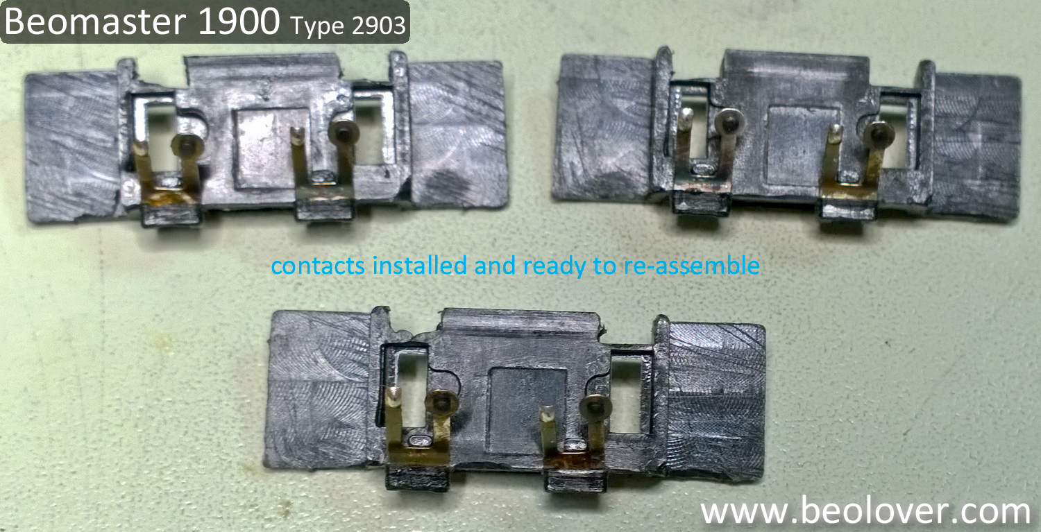
The replacement parts are just the plastic bridges. You must reuse the original contact components.
Here are the ones from this Beomaster installed in the bridges and then assembled into the slide potentiometers.


The bridges are not physically keyed so you could accidentally install them the wrong way. Make sure the bare contacts line up with the metal tracks. It is also important during the handling of the contacts to avoid disturbing the contact with the small, black coal piece.

Once the slide potentiometers are re-assembled their mounting holes to the board are keyed so the only thing to be careful with is that the 50KΩ potentiometer is placed in the Bass mounting location.


The rest of the task is just to snap and solder the potentiometers back into position on the removable board and remount it to the main board.


That is followed by a quick test play to make sure the reworked sliders function properly.


Note that I have the smoked glass display cover removed for polishing.

Monday, September 14, 2015

Beogram 4000: Zero Force Balancing and Tracking Force Calibration

The Beogram 4000 that I am restoring right now is getting ready for its first real test drive. Time to adjust the zero force balance and the setting of the correct tracking force. I made a video about this procedure a while ago on the occasion of a 4002 that crossed my bench. It is located here on my YouTube channel. The entire Beogram 4000 playlist can be accessed here. 

Here are a couple impressions from this particular Beogram 4000 restoration. The first step is zero force balancing. This requires the balancing of the arm with cartridge installed to a horizontal floating level when the force wheel is set to zero. I usually replace the locking washer of the original set-up with a M3 nut since the locking washer has too much play, which almost guarantees a change of the adjustment during the rigors of shipping. The nut holds the counterweight solidly in place:


Once the arm is balanced, the actual tracking force calibration can be undertaken. I do this with the original B&O tracking force balance. The force wheel is to be adjusted that the balance is horizontal after lowering the tip into the desired force spot on the balance:

Time to give this baby a spin!


Saturday, November 29, 2014

Beogram 4004/4002: Tracking Force Adjustment and Zero Force Balancing

I noticed that the Beogram 4002 that I am currently fixing up needed a tracking force setting of 1.5g to produce an acceptable undistorted signal with its MMC20EN cartridge. At 1g the signal would be completely distorted. A clear sign that something was wrong with the tracking force adjustment (the cartridge works well on my Beogram 4004...).

It turned out that the arm needed a zero force rebalancing. The counter weight in the back of the tone arm was way too far back. I made a video about the procedure. The video shows how to do the zero force adjustment, and then how to use the tracking force gauge that comes with B&O cartridges to get a precise adjustment of the tracking weight:


It is interesting to note that the scale on the adjustment bushing at the back of the cartridge appears to be only a rough estimate of the weight acting on the needle. In my opinion, this is not surprising considering the design of the mechanism using a variable torsion spring to press the arm down.

There is another issue with this mechanism: The adjustment screw is only held in place at the back plate with a retaining clip, which gives the counter weight 0.5-1 mm play along the arm axis. This, of course, can throw off the zero balance when the turntable is moved after an adjustment. I fixed this in Beogram 4004 with a M3 counter nut and a washer. Since the nut needs to be tightened after the adjustment the weight position changes slightly once the nut is tightened. This requires multiple attempts to get it right, but I think this is worth the effort, since this will lock the adjustment in place for long-term stability. Here is a photo of the installed nut and washer: