The Commander has been cleaned and restored (click here). Now it's time to calibrate both the transmitter (the Commander itself) and the ultrasonic receiver. The concept of this type of remote controller was common in the 70's. The early days of remote controllers. B&O used a AM system : Amplitude Modulated system. The principle is exactly the same as used in AM Radio transmitter/receivers: a high frequency wave is used as a carrier to travel long distances (the frequency you tune in on the radio) and this carrier wave is modulated with another frequency (the actual audible music sound).
The frequencies used here are off course are much, much lower since you only need to bridge a distance of +- 10m (the length of a room). Ultrasonic frequencies are anything above 20 KHz. This is the maximum a human being can hear when born. The older you get, the lower this frequency is. An elderly person (e.g. myself :-) should be happy if he still can hear frequencies of 10KHz.....Dogs can hear up to 30KHz (or even higher).
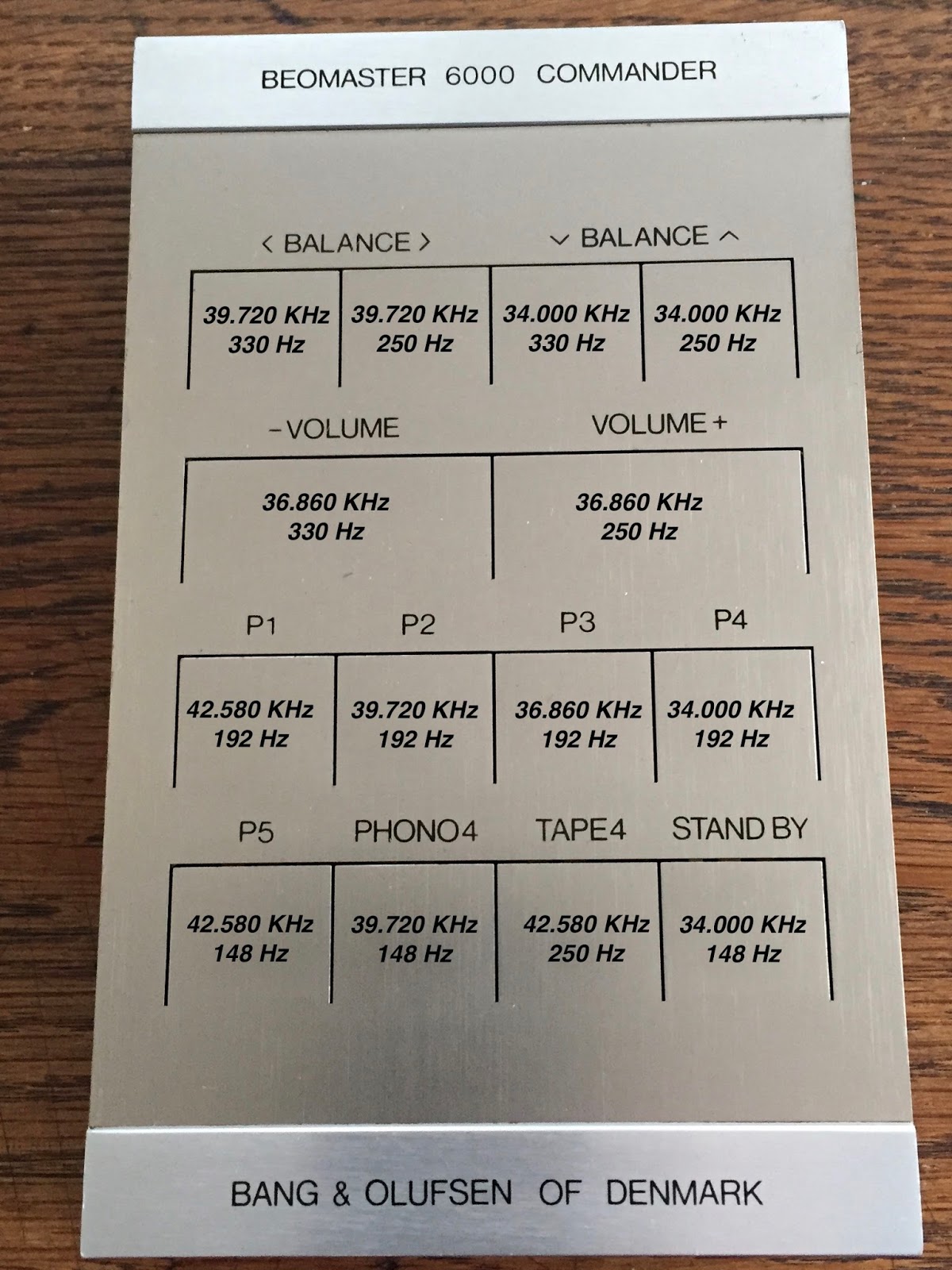
As you can see below, B&O used frequencies between 34Khz and 43KHz as carriers and frequencies between 148Hz and 330Hz as modulators. In fact, they used 4 different carriers and 4 different modulator frequencies. This gives 16 different possibilities. B&O only used 14 on the Beomaster 6000. As mentioned in my post about restoring the Commander, I don't know why they did not use all the 16 options to have e.g. also the AUX2 command selection.
I made an overview of the Commander front panel and all the corresponding values in the picture below. Every button on the Commander activates 3 circuits at the same time:
1: activating the power to the board (like an on/off switch)
2: set the correct carrier frequency
3: set the correct modulator frequency
B&O also used 100% AM modulation. In other words, the carrier signal is modulated from 0 to max level. Below an example of the 34Kz modulated with 320Hz. The frequency that you can read on the oscilloscope screen on the bottom left of 312Hz is not correct. It is difficult for an oscilloscope to measure this modulator frequency together with the carrier.

So how does one calibrate this ultrasonic system? The service manual calls for a "frequency standard" to be used. This lab device produces the exact carrier and modulator frequencies and emits them to the receiver by an ultrasonic microphone to calibrate the receiver first. A switch is provided to turn the modulation on/off if needed. Now, guess what: I don't have this "frequency standard" and never saw one either. So, I needed to find another solution.
What I wanted to do was use the transmitter as the "frequency standard". The only thing I needed to do was to make sure that this transmitter was generating the correct frequencies. Should be easy since the transmitter had trimmers to adjust. Well, it turned out that whenever you put a probe on the circuit, the internal oscillator of the transmitter started to drift and frequency changed. The whole design is a capacitive sensitive oscillator and just connecting the probe (or any other metal object) influences the oscillator. The ultrasonic microphone is also basically a capacitor with a high bias voltage to improve sensitivity. Even the ageing of this microphone influences the frequency calibration.
I decided to power up both the receiver and the transmitter at the same time and calibrate the transmitter frequencies by measuring them on the receiver side. First thing you need to do is deactivating the modulator frequencies on the transmitter to have just the carrier left (done by shorting the base and emitter of 17TR1). Otherwise it is difficult to measure. This method did work very well. Below the complete set up and an example of the incoming carrier frequency that I measured on the receiver with the f-counter. On the picture the transmitter is fully closed, but off course you need to open it to adjust the capacitive trimmers for correct frequency setting. But it's good to close, measure and open again if re-adjusting is needed because the metal keyboard may influence the calibration. Take your time for this....

One of the 4 carrier frequencies measured on the receiver side. In this case 36.860 KHz

After calibrating the 4 carriers frequencies on the transmitter side, you need to tune the receiver to these carrier signals. The receiver has 4 identical carrier demodulators that resonate at the same frequency as soon as the corresponding signal is detected from the receiver ultrasonic microphone. The only thing left is to make sure that both signals are in phase (phase coincidence). This is done by adjusting the corresponding coils on the receiver board.


The receiver has an AGC (Automatic Gain Control) circuit to make sure that the output signal is stable in value. It is obvious that the incoming signal strength depends on the distance between transmitter and receiver. With this AGC the generated signal in the receiver is a square wave of constant amplitude that is then sent to a matrix for decoding and sending the proper on/off command to the different functions (volume, tone, balance, etc.) An early version of digital I/O binary coding one could say!
The voltage of the different square wave signals need to be set equal (max +-1dB difference around 1V). The new multi-turn trimmers that I had put in earlier (click here) made it fairly easy to calibrate this.


The low modulator frequencies are "decoded" in basic the same way. However there is no adjusting possible here. By combining the carrier and modulator pulses, the matrix outputs 14 different signals to "Command" the Beomaster 6000 in the same way as you press the buttons on the Beomaster key panel.
Both the Commander and receiver board are now put aside for later mounting into the main chassis.


