Featured Post

Beolover SyncDrive: DC Platter Motor Replacement for Beogram 4002 and 4004 (Type 551x and 552x)

Late Beogram 4002 and the 4004 (Types 551x and 552x), which have DC platter motors instead of the earlier synchronous AC motors usually suff...

Showing posts with label restoring. Show all posts

Thursday, February 15, 2018

Beomaster 6000 (2702) restoration: calibration of ultrasonic remote control Commander and receiver

The Commander has been cleaned and restored (click here).  Now it's time to calibrate both the transmitter (the Commander itself) and the ultrasonic receiver. The concept of this type of remote controller was common in the 70's. The early days of remote controllers. B&O used a AM system : Amplitude Modulated system. The principle is exactly the same as used in AM Radio transmitter/receivers: a high frequency wave is used as a carrier to travel long distances (the frequency you tune in on the radio) and this carrier wave is modulated with another frequency (the actual audible music sound).

The frequencies used here are off course are much, much lower since you only need to bridge a distance of +- 10m (the length of a room). Ultrasonic frequencies are anything above 20 KHz. This is the maximum a human being can hear when born. The older you get, the lower this frequency is. An elderly person (e.g. myself :-) should be happy if he still can hear frequencies of 10KHz.....Dogs can hear up to 30KHz (or even higher).

As you can see below, B&O used  frequencies between 34Khz and 43KHz as carriers and frequencies between 148Hz and 330Hz as modulators. In fact, they used 4 different carriers and 4 different modulator frequencies. This gives 16 different possibilities. B&O only used 14 on the Beomaster 6000. As mentioned in my post about restoring the Commander, I don't know why they did not use all the 16 options to have e.g. also the AUX2 command selection. 

I made an overview of the Commander front panel and all the corresponding values in the picture below. Every button on the Commander activates 3 circuits at the same time:

1: activating the power to the board (like an on/off switch)
2: set the correct carrier frequency
3: set the correct modulator frequency
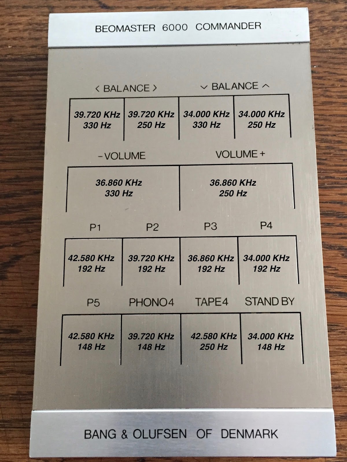


B&O also used 100% AM modulation. In other words, the carrier signal is modulated from 0 to max level. Below an example of the 34Kz modulated with 320Hz. The frequency that you can read on the oscilloscope screen on the bottom left of 312Hz is not correct. It is difficult for an oscilloscope to measure this modulator frequency together with the carrier.


So how does one calibrate this ultrasonic system? The service manual calls for a "frequency standard" to be used. This lab device produces the exact carrier and modulator frequencies and emits them to the receiver by an ultrasonic microphone to calibrate the receiver first.  A switch is provided to turn the modulation on/off if needed. Now, guess what: I don't  have this "frequency standard" and never saw one either. So, I needed to find another solution. 

What I wanted to do was use the transmitter as the "frequency standard". The only thing I needed to do was to make sure that this transmitter was generating the correct frequencies. Should be easy since the transmitter had trimmers to adjust. Well, it turned out that whenever you put a probe on the circuit, the internal oscillator of the transmitter started to drift and frequency changed. The whole design is a capacitive sensitive oscillator and just connecting the probe (or any other metal object) influences the oscillator. The ultrasonic microphone is also basically a capacitor with a high bias voltage to improve sensitivity.  Even the ageing of this microphone influences the frequency calibration.

I decided to power up both the receiver and the transmitter at the same time and calibrate the transmitter frequencies by measuring them on the receiver side. First thing you need to do is deactivating the modulator frequencies on the transmitter to have just the carrier left (done by shorting the base and emitter of 17TR1). Otherwise it is difficult to measure. This method did work very well. Below the complete set up and an example of the incoming carrier frequency that I measured on the receiver with the f-counter. On the picture the transmitter is fully closed, but off course you need to open it to adjust the capacitive trimmers for correct frequency setting. But it's good to close, measure and open again if re-adjusting is needed because the metal keyboard may influence the calibration. Take your time for this....


 One of the 4 carrier frequencies measured on the receiver side. In this case 36.860 KHz


After calibrating the 4 carriers frequencies on the transmitter side, you need to tune the receiver to these carrier signals. The receiver has 4 identical carrier demodulators that resonate at the same frequency as soon as the corresponding signal is detected from the receiver ultrasonic microphone. The only thing left is to make sure that both signals are in phase (phase coincidence). This is done by adjusting the corresponding coils on the receiver board.


The receiver has an AGC (Automatic Gain Control) circuit to make sure that the output signal is stable in value. It is obvious that the incoming signal strength depends on the distance between transmitter and receiver. With this AGC the generated signal in the receiver is a square wave of constant amplitude that is then sent to a matrix for decoding and sending the proper on/off command to the different functions (volume, tone, balance, etc.) An early version of digital I/O binary coding one could say!

The voltage of the different square wave signals need to be set equal (max +-1dB difference around 1V). The new multi-turn trimmers that I had put in earlier (click here) made it fairly easy to calibrate this.


The low modulator  frequencies are "decoded" in basic the same way. However there is no adjusting possible here. By combining the carrier and modulator pulses, the matrix outputs 14 different signals to "Command" the Beomaster 6000 in the same way as you press the buttons on the Beomaster key panel. 

Both the Commander and receiver board are now put aside for later mounting into the main chassis.


Saturday, January 27, 2018

Beomaster 6000 (2702) restoration: recapping output PCB + trimmers

After the complete dismantling of the Beomaster 6000 quad it is time to start the restoration work. I decided to tackle the output PCB first (not the darlingtons yet). This PCB houses the 4 power output driver networks and the bank of push buttons for different actions like: front and rear speakers, loudness, hi/low filters, mono, stereo, SQ decoder, ambio sound and AFC / silent tuning. This bord is long and small and sits in a metal subframe. It is not very well fixed in place and therefore, due to warping of the board, the risk of a short circuit between the print side of the board and the metal chassis is high. NEVER attempt to power up the board while is sits in the metal frame without properly isolating the board from the chassis. I usually put a piece of carton in between (that stays in there permanently). But since the whole unit is now disassembled, a more permanent solution will need to be found (see my next blog about this).


Replacing electrolyte capacitors and tantalum's in a vintage electronic unit is always a good idea. They start drying out, leak or loose there value. As you will see on the picture below, one of the ROE caps had a serious crack and was leaking. Very common. I always replace electrolyte capacitors with quality 105C ones that have a longer lifespan. The tantalum's are also replaced with quality electrolytes. I like to use MKS's, but they did not fit in the narrow space on this board. I have seen exploded tantalum's in the past (in a Beocord 5000) and several ones that where short circuit. This failure mode, specifically on older types, is called Field Crystallization and is the major reason for degradation and catastrophic failures of solid tantalum capacitors. It causes a dielectric breakdown and happens very fast (milliseconds).


The recapped output PCB


As you may notice, I also changed the trimmers for the bias current setting (quiescent current). The originals are small 1-turn types that are a bit difficult to reach and not easy to set at the correct value. Moreover, the risk of making a short circuit when setting them with a non isolated screwdriver is high (some readers will probably smile now...!). I replaced them with encapsulated 22 turn trimmers. I prefer to use the long type since they give a bit more stability and makes it easier to reach the small turning knob. Off course, one needs to redirect the wires to make them fit into the 3 existing holes from the old trimmers. It's a good idea to make sure the turning direction of the new ones versus the old ones is the same (fully anti-clockwise for lowest current setting).


And here's a view of how the trimmers are rewired. Make sure the wires are not touching each other. Use some isolating tape or heat shrink tubes.


Earlier on I noted already that one of the front right output stage darlington transistors was fried. It was time now to check if the driver section was still OK. And it was not. The emitter resistor of 0,12 ohm was "open" and the BC312 was also fried. I have spare original ones available so replaced them as well. 

This is a picture of all the caps, trimmers, resistor and transistor that where replaced on this board. Old en new together !


And here are the 4 tantalum's that where replaced with electrolytes.


Next I will tackle the subframe with the 8 darlington transistor and there cooling plates.

Thursday, March 9, 2017

Beomaster 8000: Updating the Displays - Completed

Today I finished replacing a set of Beomaster 8000 display LEDs with SMD LEDs. This set had numerous faulty display segments so it was badly in need of repair.

I was a little disappointed that my SMD work station method of doing this task fell short of expectations. In my earlier restoration of the Beocord 9000 displays the work station method worked quite well and I felt like I only needed to perfect the process a little before it became my new way of doing these displays. Now I think that was just beginner's luck. Since that first display repair the SMD work station technique has meant a lot more rework and waste of new SMD LEDs (that had to be tossed when the installation failed).

The problem with the SMD work station is that even with minimal air flow, the SMD LEDs can shift during soldering. Even in the case where the solder pads are small I usually run into over half the LEDs not soldering in the position they need to be. With these Beosystem LED displays it is critical that the LEDs stay within a narrow range in their positioning. The reason for that is they have to fit nicely in the slots of the plastic housing that guides the light.

So after that hopeful experiment I have reverted to the tried and true manual soldering process.

To show what I am talking about here is the preparation for the Beomaster 8000 channel balance display. This picture shows the SMD LEDs in place on their solder paste ready for the heat to be applied.


After the board heater and heat gun melted the solder, the result was quite unsatisfactory.


The LEDs circled in red were not successful. I had to toss those LEDs as I don't trust them to be reused once I remove them. These SMD LED devices are pretty delicate so I don't want to risk them failing later on.

Here is the reworked board after manually repairing it with old fashioned tweezers and soldering iron. I used my de-soldering gun to clean up the excess solder.


Now that I decided to change over to the manual soldering method I prepared the next board by cleaning with alcohol and tinning the solder pads. This is the Beomaster 8000 volume level display.


Before placing the SMD LEDs I apply some solder flux with a syringe. The SMD board heater at least provides a nice way to hold the board in place while I work on it.


Here is the completed volume level display. As I did each display I was able to refer back to my photos I posted in the previous post that show the LED orientation on the pads. That was very helpful as I could just look at my smart phone for the reference photo as I placed and soldered these LEDs in place.


Next is the Beomaster 8000 function display. Here is the prepped board.


...and the finished board.


Finally the last board, the FM frequency display board. These display restorations are probably the most difficult job of the entire restoration. The work is very trying on one's patience as it is easy to get frustrated if you can't keep a steady hand. You have to be in the right frame of mind when doing this. 

Here is the last board before tinning. The marks between the pads is where I used a razor knife to cut the tiny pad the original LED mounted to. I found that trying to leave in place is risky because it is such a narrow gap. It is easy for solder to bridge that gap and cutting it out leaves a perfect gap for these SMD LED components.

Here is the board tinned and with solder flux in place on the pads.

The last board is now complete. One other note about the manual soldering process. I often just solder one side of the SMD LED to hold it, then test fit the light guide piece to make sure the LED component is centered in the slot. That is an extra step but it actually saves rework time and risk in destroying a good SMD LED. After I verified the fit I solder the other side of the LED.

Now it is time for the display burn-in test. I reworked my test jig since the last post and I am now going to leave these displays operating for 24 hours to make sure none of them are faulty.

Just for a reference I put the channel balance display completely back together (just pressed together, not permanent yet), the volume display and function display with just the light guide attached, and the FM frequency display bare. You can see the progression that the parts play in the final look of the display.

While these display modules are testing I can start work on the Beomaster display board recapping and the Microcomputer board recapping.


Friday, January 30, 2015

Beocord 5000 (4715/4716): Test Drive

A happy day! The second Beocord 5000 (4715/4716) is back together and is playing happily with its friends, the Beomaster 6000 4-Channel and the Beogram 4002. I decided that the soundtrack of 'Alfie' by Sonny Rollins would be a nice celebratory first recording:


Alfie is definitely one of my favorite Michael Caine movies, and the sound track is just awesome! Here are some impressions of the recording session: