Featured Post

Beolover SyncDrive: DC Platter Motor Replacement for Beogram 4002 and 4004 (Type 551x and 552x)

Late Beogram 4002 and the 4004 (Types 551x and 552x), which have DC platter motors instead of the earlier synchronous AC motors usually suff...

Showing posts with label ultrasonic. Show all posts

Friday, May 25, 2018

Beogram 4002: Restoration of a Very Oily DC Platter Motor

I recently received a Beogram 4002 DC platter motor from Berlin, Germany for restoration. I immediately noticed that the motor was quite oily on the outside, probably from an attempt to lubricate it to enhance RPM stability. This shows the motor as received:
I disassembled it to extract the bearings for oil infusion:
The bearings are on the black pad up front. The inside of the motor was also very oily, but of course this does not help the bearings, since they need to be infused with oil under vacuum. This is necessary to pull out the air in the pores of the Oilite brass material that the new oil can penetrate into the bearing. This shows the bearings submerged in motor oil after pulling a vacuum:
The bubbles rising from them is the air exiting the bearing. This process usually takes 24-72 hrs depending on the state of the bearings.
After the bubbling stopped I extracted the bearings from the oil and put them on a paper towel to wick the excess oil away:
Then I re-assembled the motor again and implanted it into one of my 4002s. Then I ran a 24 hrs RPM stability test with the BeoloverRPM device, which allows the logging of the RPM for extended periods of time:
The BeoloverRPM is available to other enthusiasts. Just send me an email or use the contact form on the right. The very unstable blue curve on the graph below is what I measured:
This indicated that I was not done yet with this motor. First I thought the motor probably needed new spark suppressors since that usually causes large downward spikes, but the overall pattern looked somewhat different. Finally, I remembered that I had a similar issue when I just started developing the restoration procedure for these motors a few years back. Initially, I also thought that simply putting a lot of oil in everything would probably help. But when I squirted some of the oil on the commutator of the motor (to 'further reduce friction'...;-), the motor performance dramatically worsened, like in this case. It seems that the oil creates an insulating layer on the rotor impeding the current flow though the rotor, which causes RPM reductions.
So I took the motor apart again and cleaned rotor and brush carrier (together with the pulley - it was also oily and I worried that I would not be able to glue it to the shaft once done) in my ultrasonic cleaner:
I put it in warm water with some dish washing detergent. Immediately after starting the cleaner the water became very cloudy.
This indicated that an emulsion was forming between the oil on the parts and the water. I replaced the water three times and ran the cleaner a couple minutes in each batch. Then the water finally stayed clear and I gave it a fifth run in pure ethanol to get the water out of the rotor windings etc...The I put everything out for drying:
After re-assembling, I tested the motor for another 24 hrs and I was able to measure the nice red curve in the above graph. So everything is fine now with this motor, and it is ready for return shipping to Berlin!

Thursday, February 15, 2018

Beomaster 6000 (2702) restoration: calibration of ultrasonic remote control Commander and receiver

The Commander has been cleaned and restored (click here).  Now it's time to calibrate both the transmitter (the Commander itself) and the ultrasonic receiver. The concept of this type of remote controller was common in the 70's. The early days of remote controllers. B&O used a AM system : Amplitude Modulated system. The principle is exactly the same as used in AM Radio transmitter/receivers: a high frequency wave is used as a carrier to travel long distances (the frequency you tune in on the radio) and this carrier wave is modulated with another frequency (the actual audible music sound).

The frequencies used here are off course are much, much lower since you only need to bridge a distance of +- 10m (the length of a room). Ultrasonic frequencies are anything above 20 KHz. This is the maximum a human being can hear when born. The older you get, the lower this frequency is. An elderly person (e.g. myself :-) should be happy if he still can hear frequencies of 10KHz.....Dogs can hear up to 30KHz (or even higher).

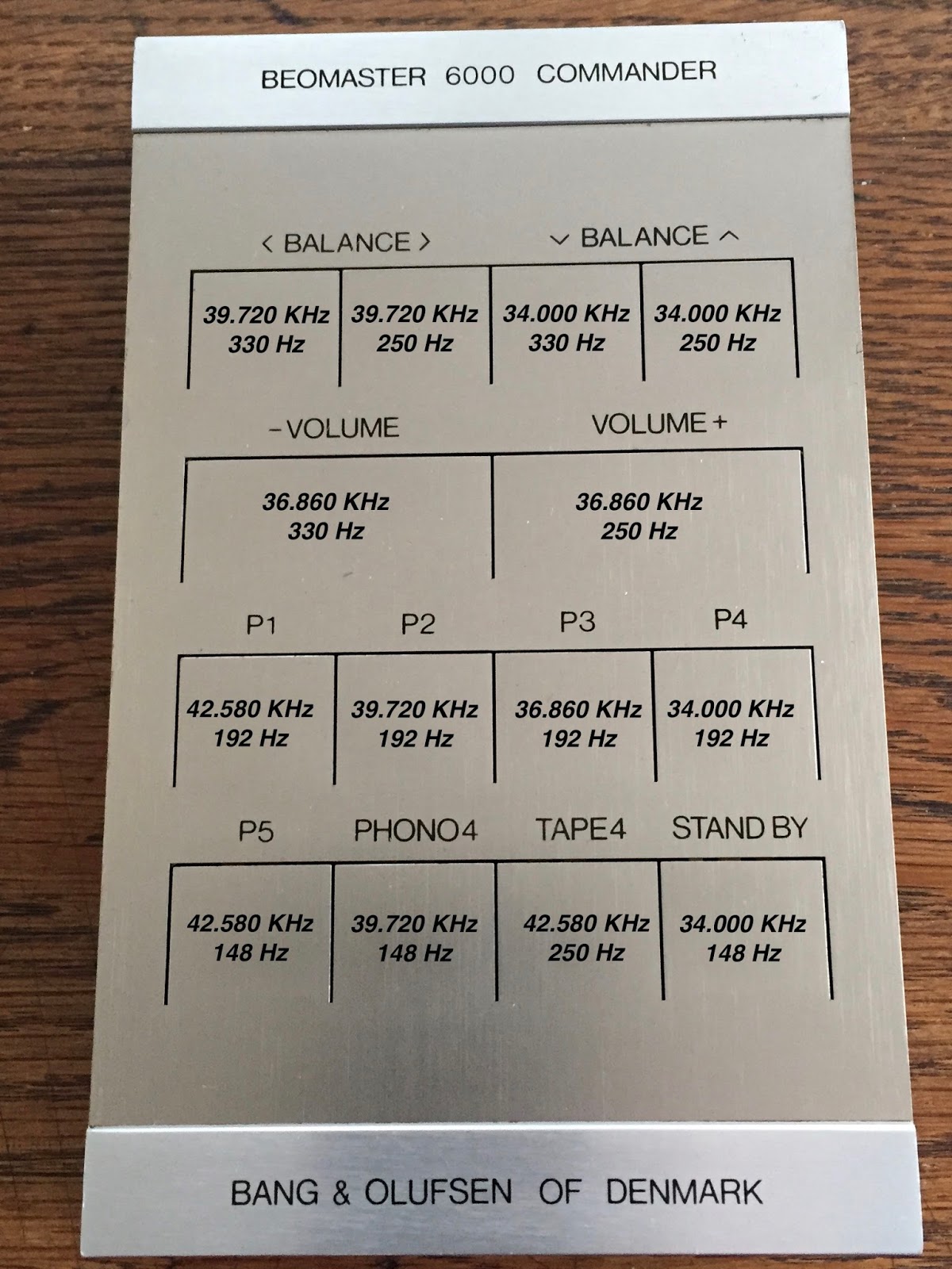
As you can see below, B&O used  frequencies between 34Khz and 43KHz as carriers and frequencies between 148Hz and 330Hz as modulators. In fact, they used 4 different carriers and 4 different modulator frequencies. This gives 16 different possibilities. B&O only used 14 on the Beomaster 6000. As mentioned in my post about restoring the Commander, I don't know why they did not use all the 16 options to have e.g. also the AUX2 command selection. 

I made an overview of the Commander front panel and all the corresponding values in the picture below. Every button on the Commander activates 3 circuits at the same time:

1: activating the power to the board (like an on/off switch)
2: set the correct carrier frequency
3: set the correct modulator frequency


B&O also used 100% AM modulation. In other words, the carrier signal is modulated from 0 to max level. Below an example of the 34Kz modulated with 320Hz. The frequency that you can read on the oscilloscope screen on the bottom left of 312Hz is not correct. It is difficult for an oscilloscope to measure this modulator frequency together with the carrier.


So how does one calibrate this ultrasonic system? The service manual calls for a "frequency standard" to be used. This lab device produces the exact carrier and modulator frequencies and emits them to the receiver by an ultrasonic microphone to calibrate the receiver first.  A switch is provided to turn the modulation on/off if needed. Now, guess what: I don't  have this "frequency standard" and never saw one either. So, I needed to find another solution. 

What I wanted to do was use the transmitter as the "frequency standard". The only thing I needed to do was to make sure that this transmitter was generating the correct frequencies. Should be easy since the transmitter had trimmers to adjust. Well, it turned out that whenever you put a probe on the circuit, the internal oscillator of the transmitter started to drift and frequency changed. The whole design is a capacitive sensitive oscillator and just connecting the probe (or any other metal object) influences the oscillator. The ultrasonic microphone is also basically a capacitor with a high bias voltage to improve sensitivity.  Even the ageing of this microphone influences the frequency calibration.

I decided to power up both the receiver and the transmitter at the same time and calibrate the transmitter frequencies by measuring them on the receiver side. First thing you need to do is deactivating the modulator frequencies on the transmitter to have just the carrier left (done by shorting the base and emitter of 17TR1). Otherwise it is difficult to measure. This method did work very well. Below the complete set up and an example of the incoming carrier frequency that I measured on the receiver with the f-counter. On the picture the transmitter is fully closed, but off course you need to open it to adjust the capacitive trimmers for correct frequency setting. But it's good to close, measure and open again if re-adjusting is needed because the metal keyboard may influence the calibration. Take your time for this....


 One of the 4 carrier frequencies measured on the receiver side. In this case 36.860 KHz


After calibrating the 4 carriers frequencies on the transmitter side, you need to tune the receiver to these carrier signals. The receiver has 4 identical carrier demodulators that resonate at the same frequency as soon as the corresponding signal is detected from the receiver ultrasonic microphone. The only thing left is to make sure that both signals are in phase (phase coincidence). This is done by adjusting the corresponding coils on the receiver board.


The receiver has an AGC (Automatic Gain Control) circuit to make sure that the output signal is stable in value. It is obvious that the incoming signal strength depends on the distance between transmitter and receiver. With this AGC the generated signal in the receiver is a square wave of constant amplitude that is then sent to a matrix for decoding and sending the proper on/off command to the different functions (volume, tone, balance, etc.) An early version of digital I/O binary coding one could say!

The voltage of the different square wave signals need to be set equal (max +-1dB difference around 1V). The new multi-turn trimmers that I had put in earlier (click here) made it fairly easy to calibrate this.


The low modulator  frequencies are "decoded" in basic the same way. However there is no adjusting possible here. By combining the carrier and modulator pulses, the matrix outputs 14 different signals to "Command" the Beomaster 6000 in the same way as you press the buttons on the Beomaster key panel. 

Both the Commander and receiver board are now put aside for later mounting into the main chassis.


Beomaster 6000 (2702) restoration: restoring the Commander - remote controller

This Beomaster 6000 quad came with the original remote control, called "Beomaster 6000 Commander" ! In the past I have seen different names printed on this device however: like "Beomaster 6000 control module". It is an ultrasonic remote control device that allows some basic functions: volume up/down, balance up/down/left/right, FM presets P1 to P5, input selection for Phone4 & Tape4 and stand-by. No idea why they did not include the AUX2 for example. Technically there is no excuse for not doing it.


The Commander did not look like it was heavily used. Just the usual small marks and scratches, but nothing uncommon.  After opening it, the same picture inside. Very little dust or dirt. Off course, the contacts needed to be cleaned and the board recapped (only 2 capacitors). And the trimmer replaced.


There is only one good way in cleaning the contacts: take them out! And that turned out to be more difficult than expected. The (4) bars with contacts are soldered onto the board. But even after desoldering everything, they did not want to come out. Closer (very closer...) inspection revealed that these bars have tiny retainers that keep the bars in the plastic "frame". You need to straighten these retainers in order to get the bars out and that was microscopic work.


Once out, it was just a matter of cleaning with a fiber pen and further cleaning & coating with Deoxit Gold. I noticed some small scratches on the contact bars. Probably from an earlier attempt to try to clean them with sand paper and without taking them out. 


After cleaning the bars they were soldered back in place. The gap between the bars and the small gold-plated "dots/contacts" is about 1 mm.  And yes, while your in there, clean the battery compartment contacts as well!

The whole board is fitted with only one bolt in the middle. Strange. But it does allow for some adjustment to bring the board closer or further away from the key panel. That is why the nut on the bolt is sealed with red paint.


A good looking Beomaster 6000 Commander I must say! Time to recalibrate this transmitter and the receiver.


Saturday, February 3, 2018

Beomaster 6000 (2702) restoration: ultrasonic receiver and tone amplifier

Another PCB where everything is very tight and space is limited: "PCB 14, remote control receiver". Luckily not that many capacitors but also a few trimmers that I wanted to replace. And there I found again something interesting: the trimmers only had 2 legs ! The slider contact that typically sits in the middle, was here one of the two outer contacts. Never seen this before. So I had to modify the multi turn trimmers that I wanted to use. Not a big issue however.


The added advantage of using this type of multi turn trimmer on this PCB is that it is now reachable from the top and does allow setting without removing the PCB. This was not the case with the original trimmers.


Recapping the tone amplifier was pretty straight forward. All easy reachable capacitors. As you can see, this board is still attached tot the potentiometers (the string of coloured wires).  I did not want to unsolder all those wires unnecessarily . 


Wednesday, September 14, 2016

CleanerVinyl Pro Released: Clean Up to 12 Vinyl Records in One Go!

A few of my CleanerVinyl customers inquired about a higher throughput version of my original CleanerVinyl design. The original design is very easy to use, but only allows the cleaning of one record at a time (that is why I rebranded it as CleanerVinyl One...;-). Inspired by these comments, I set out to do a redesign, which came together in the last few weeks. The new pro version is a much more massive design. It is built from precision-machined stainless steel and aluminum parts and also uses brass bearings to support the weight of the record stack. It can take on up to 12 records at a time. Check out my redesigned CleanerVinyl website, and the CleanerVinyl Pro video below. Enjoy!

Wednesday, April 13, 2016

CleanerVinyl: Beolover's Approach to Ultrasonic Vinyl Record Cleaning

While I am pretty happy about my initial approach to vinyl cleaning, ultrasonic cleaning is the superior technology and it is just perfect for vinyl records! Hence, I always longed for an ultrasonic vinyl cleaner, but the currently available dedicated products are all very expensive and out of my reach. It just does not seem to make sense spending $3-4k on an ultrasonic vinyl cleaning device (unless you own a record store...;-). I'd rather spend the money on my rapidly expanding vinyl collection!

So I set out to design a cost effective but elegant solution that would allow me the use of a standard industrial grade ultrasonic bath. Ultrasonic cleaning technology has become a commodity and ebay is flooded with quality units in the $100-200 range that get the job done. The particular unit I selected has a 180W transducer (similar to what the 'competition' uses in their dedicated ultrasonic vinyl cleaners) and the bath size is just enough to hold a record deep enough to get to the final groove.

So, without further ado...(drum roll!!)...I give you the CleanerVinyl ultrasonic vinyl cleaning system: