Featured Post

Beolover SyncDrive: DC Platter Motor Replacement for Beogram 4002 and 4004 (Type 551x and 552x)

Late Beogram 4002 and the 4004 (Types 551x and 552x), which have DC platter motors instead of the earlier synchronous AC motors usually suff...

Showing posts with label 2019MJBM2400. Show all posts

Friday, July 12, 2019

Beomaster 2400 Type 2902: Lamp replacement and voltage checks

This Beomaster 2400 has reached the final stages of the restoration.  I replaced the indicator lamps and performed the first voltage checks on the receiver today.

On the Beomaster I replace the lamps that are only for illuminating a display function with LED devices. There are five lamps that are part of the circuit that they display the state of.  Those lamps must remain incandescent type bulbs. I typically get my incandescent lamps from Martin Olsen as I know he will source me the correct type.

Here is the before picture of the Beomaster 2400 volume indicator lamps.


....and here are the replacements. These are two that must be incandescent type bulbs.


Next are the tone control lamps (Bass, Treble and Balance).  These are lamps that can really benefit by changing to LED type bulbs. The sliding indicator masks on this Beomaster unit are deteriorated from the heat of the original incandescent bulbs.


The replacement LED lamps give off a lot less heat and should not damage the replacement indicator masks I am going to install.

Here are the original lamps.


Here are the replacement LED assemblies I created. Note that the polarity has to be correct on the LED lamps.


The LED lamps must have a current limiting resistor.

The source selection display board is the last board to replace lamps on. Here is the original configuration.


The far left bulb and the two incandescent bulbs on the far right must remain incandescent type bulbs.
The rest will be changed to LED devices. The red LED for Standby indication doesn't need to be changed if it still works.


Time to test the lamp replacements.

Standby works


The Standby lamp is a good indication that +15VDC is good on this Beomaster.  Time to check the power supply voltages.

Here is the +15VDC reservoir capacitor. The voltage here looks good. It is prior to +15VDC voltage regulation.


Selecting a source (i.e. FM5) I see that I have +15V so I performed that service manual adjustment.


While the Beomaster is still open where I can (barely) get to the left and right channel no-load current adjustment pots I performed those adjustments.

It is too difficult to place probes across the emitter resistor from the component side of the board while it is installed so I attach my probe wires on the trace side.


Now I can easily measure the voltage across one of the left and right channel emitter resistors for the no-load current adjustments.

Both channels dialed in easily. Well...relatively easy.  The trim pots for this adjustment are not the easiest to reach.


Note that I had the polarity of the probes reversed on the right channel measurement. It doesn't matter for this adjustment check. I am only concerned that I set the voltage on the meter to 12mV.

I also checked the ±31V rail voltages for the output amplifier. They measured good...probe polarity is important here :-).


The final service manual voltage checks I performed were the tuning voltages. There is one adjustment for FM1 and another for FM5.


So far so good on the reassembly and electrical checks.


I will finish reassembling this Beomaster then take it over to the test bench for some functional testing. I did perform a sneak peak by connecting up an FM antenna and an iPod Nano to the Tape source and listened to music via the headphones jack. The Beomaster 2400 is playing music again. Tone controls all work so a nice milestone has been reached on this project.


I will leave the Beomaster 2400 playing an FM station while hooked up to a pair of Beovox S75 speakers I keep in my workshop.  While it is busy doing that I can work on assembling the new display indicator masks for the bass, treble and balance controls.

Tuesday, July 9, 2019

Beomaster 2400 Type 2902: Tone controls slider bridge repair

A common failure on the Beomaster 1900 and 2400 receivers is with the tone control slider assemblies. Each slider has a left and right channel contact that slide up and down together on a plastic bridge. The contacts are press fitted onto the bridge and held by a plastic post and bar. Over time the plastic bar breaks and the contact comes loose. That results in the slide control no longer working.

Martin Olsen on Beoworld makes replacement slider bridge kits specifically for the Beomaster 1900 and 2400 units. I have used his kit on all of my Beomaster 1900 restorations so far and will continue with this Beomaster 2400 unit. The replacement bridge parts have a beefier bar for the contacts to mount to than the original part.

Here are each of the three tone control sliders disassembled from the tone control board starting from left to right with the Bass slider first.


As you can see the Bass slider has the usual broken tab but it also has a problem where one of the contacts is missing.  I did not see it anywhere in the Beomaster cabinet so it is long gone.  Fortunately I have a spare.

Next is the Treble slider.


Both left and right channel contacts are present with the Treble slider but its slider bridge tabs are broken.

Last is the Balance slider.


The Balance slider has its slider bridge all intact.  I will still replace it along with the Bass and Treble sliders as this slider control is likely to break in the future.  Martin's repair kit comes with three replacement bridges so I will use all of them.

Besides replacing the slider bridge I clean the metal contacts and the rails.
The repair for all three slider control bridges is the same so I will just show one in detail here.


...and here are all three slider controls re-installed on the Beomaster 2400 Tone Control board.


Sunday, July 7, 2019

Beomaster 2400 Type 2902: Recapping the tone control board and FM tuner

To wrap up the capacitor replacement on this Beomaster 2400 restoration there is just one capacitor in the FM tuner box and a handful of capacitors on the tone control board.

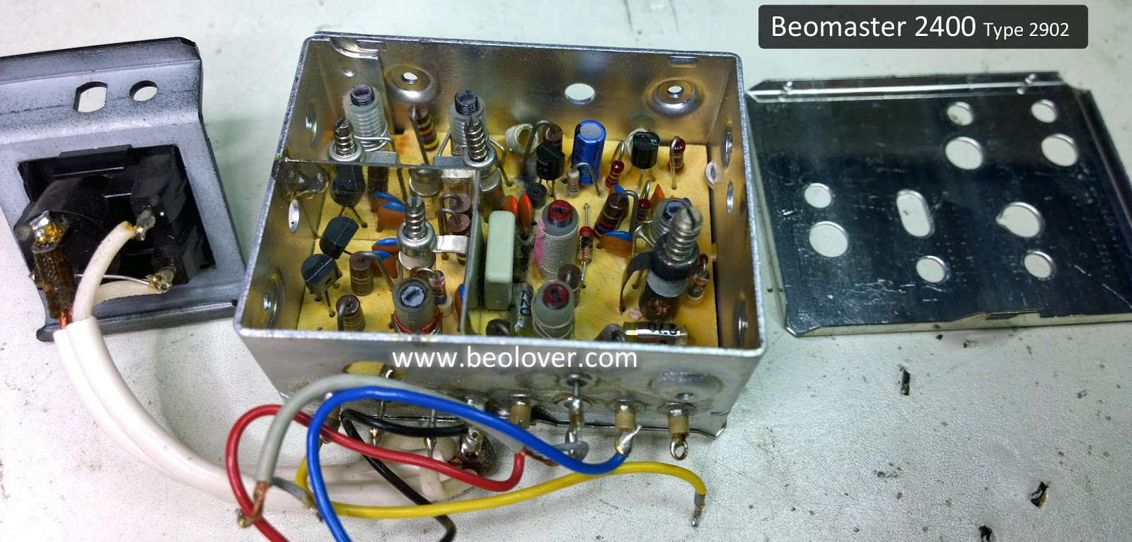
The FM tuner box has top and bottom lids that must be removed. There is a shield wire that must be desoldered from the bottom lid before it can be opened. The bottom lid is necessary to desolder the lone 10uF capacitor leads.


Under the top lid we can find the capacitor that will be replaced.


...and here is the recapped version


The last board to recap is the control board for the tone controls and FM tuning. There are just ten capacitors to replace.  Here is the before and after picture.


I am not finished with this tone control board yet. The next task is to remove the Bass, Treble and Balance slide control devices to rebuild them.

Saturday, July 6, 2019

Beomaster 2400 Type 2902: Recapping the main board and the volume control board

I completed the capacitor replacement on the Beomaster 2400 main board and volume control board. This included replacing the reservoir capacitors and the idle current adjustment trim pots for both channels.


The Beomaster 1900 and 2400 receivers are not my favorite units to replace capacitors on. They are very compact and low profile which make things a little cramped inside. Unlike the large Beomaster 8000 these smaller Bang & Olufsen receivers do not have easy accessible and removable circuit boards for working on.

Here is another picture for the Beomaster 2400 before the main board recapping.

You can see there are a lot of capacitors to change out. About eighty capacitors out of the ninety-nine total I will be replacing.  I can't easily disconnect the main board from the rest of the Beomaster 2400 to remove it for recapping as it has several hard-wired connections to the transformer and power supply.  On a Beomaster 1900 one time I removed everything from the cabinet chassis but that still made maneuvering the board awkward as I had the weight of the still connected transformer to deal with.

Since then I like to disconnect the FM tuner box, reservoir capacitors and heatsinks so I can switch from front and back of the main board while recapping.


I remove a couple of solid wires to the transformer to avoid breaking them while working on the main board.


After that it is a careful and tedious ordeal of desoldering and soldering while switching from the component side of the board to the trace side...back and forth.  This is another picture of the main board after the recapping work was completed.


There was one 10uF, 63VDC capacitor under the metal shield box for the remote control circuit.


I usually replace capacitors with values of 4.7uF and smaller with WIMA MKS capacitors.
An exception is if the WIMA won't fit well as with the two small 4.7uF capacitors on this small B&O adapter board.


This picture shows the two Beomaster 2400 idle current trim pots after I replaced the originals.


When installed back in the cabinet frame the emitter resistors are difficult to attach probes to for making the idle current (or no-load current) adjustment. While I have the main board in service position I like to make sure the leads on the emitter resistors are long enough on the trace side of the board to clip measurement probes to.

This picture shows the +15VDC supply reservoir capacitor after the recap. I used a little bit of Aleene's glue to secure it in place.


The two large 5000uF reservoir capacitors are kind of a pain to change out on these types of Beomaster units. The original capacitor terminals are soldered together as well as all of the connected wires.


In my replacement reservoir capacitor assembly I use small terminal connectors to attach the wires to the capacitors and the two capacitors to each other.


That is a more secure connection and makes future desoldering of the reservoir capacitors easier.

The small volume control board only has six small capacitors to replace.


That leaves one capacitor in the FM tuner box to replace and a few capacitors on the tone control and FM tuning control board. Then the recap work will be complete.