Featured Post

Beolover SyncDrive: DC Platter Motor Replacement for Beogram 4002 and 4004 (Type 551x and 552x)

Late Beogram 4002 and the 4004 (Types 551x and 552x), which have DC platter motors instead of the earlier synchronous AC motors usually suff...

Showing posts with label sil-pad. Show all posts

Sunday, January 31, 2021

A Pair of Beomaster 1900 Receivers for Restoration: Unit #1 Reassembly for Testing and a Power Problem

 The next step before testing the Beomaster 1900 was to reinstall the four output transistors that mount on the rear heatsinks. I had removed the heatsinks and the original thermal insulating paste. On the reassembly I like to use modern SIL-Pad thermal insulators. They do a great job and don't have the mess that thermal paste does.

Here are the parts laid out for reassembly.


I like the way Bang & Olufsen chose to mount the transistors to the heatsinks. They use curved, metal spring clips that press the plastic face of the transistor against the heatsink...sandwiching the thermal insulating material in between.

Here are the output transistors reinstalled.


Everything is installed that is necessary to start testing the Beomaster 1900.

It only took the amount of time for me to connect up the variac and dim bulb tester to try powering up the Beomaster to discover a problem.

The Beomaster 1900's +15 VDC power supply was not turning on. No Standby lamp illuminated.
I exercised the main power switch again to make sure it wasn't dirty but nothing.

I unplugged the power cord and started to check around the +15 VDC power supply.  I could not measure anything across its fuse.  I had noticed the fuse holders were badly tarnished but this unit had powered up prior to starting the restoration. I pulled the fuse and it was okay. I just couldn't get anything through it from the fuse holders.

Here are the fuse holder clips and where I removed them from on the board.


Age has not been kind to these fuse holders. I remember now that the original bridge rectifier had been replaced on this Beomaster and there was a large, charred mark under where the bridge rectifier had been mounted. It is likely some big power event had occurred sometime in the past.

In any case I need to order some of these fuse holders on the +15 VDC power supply line.  If I order them today Mouser will deliver them on Tuesday.

The power supply incident got me thinking about all of the input power to the Beomaster 1900. I had seen a bad power switch on a Beomaster 2400 in the past so I should look at this one more closely.

I am glad I did. The switch actually measures good and I did some cleaning on it with Deoxit.  However, I found a cut in the insulation on one of the main power wires delivering line power to the Beomaster.  It probably wouldn't hurt anything but I don't like bare wires where they are not supposed to be.


I will rework the wiring on the power switch and fix that problem while I am waiting for the fuse holder clips to arrive.

Here is the cleaned up and prepared power switch.


Wednesday, October 28, 2020

Beomaster 2400 Type 2902 - Canada Project Power Supply & No-Load Current Adjustment

 The hard parts of the Beomaster 2400 are completed. It is time to put the receiver back together so I can do some basic voltage checks.  

First though I need to re-attach the four output amplifier transistors that mount to the Beomaster 2400 heat sinks. I like using the Sil-Pad thermal interface product rather than the white thermal paste in these low profile receivers. The Sil-Pads do a good job and don't have the mess that paste does.


At this point I decided I wanted to check the Beomaster 2400 restoration I had done so far by powering up the Beomaster and performing some basic service manual tests.  In order to do that I re-attached the Filter & Tone Control board along with the Beomaster 2400 lamp boards.


If you think your eyes are playing tricks on you in the above two photos they are not. I didn't really like the new replacement 2C92 2200uF, 25V capacitor for +15VDC in the Beomaster.  The markings on that capacitor were kind of strange. It wasn't as clear as it should be about which end of the axial capacitor was positive and negative. Normally the (-) marking is a distinct arrow pointing at the negative end. This capacitor looks like it points in both directors and the data sheet on it wasn't any help...so I switched it out with a Vishay 2200uF, 25V, axial capacitor that has clear polarity markings.

Plugging in the Beomaster 2400 and turning the master power switch on resulted in the red Standby LED illuminating.

The first test I performed was for the +15VDC supply. I adjusted it to the required +15V per the service manual.


Next were the left and right channel no-load current adjustments.
The space for attaching measurement wires and adjusting the trimmers is very cramped in the Beomaster 2400. My method of performing the adjustment is to mount the measurement wires across the emitter resistors from the bottom of the Beomaster 2400 main board.


That provides the leads I need to attach my DMM for the no-load current measurements.
I adjusted the left channel for the target 12mV across the emitter resistor test points.


Then I adjusted the right channel.


So far everything looks good.

I want to measure the Beomaster 2400 muting circuit while I have the cover off and the original lamps still attached. That is the volume muting that occurs when the music source is switched.  Pressing one of the Beomaster music source switches should send a volume mute signal to the volume control until the source switching is completed.

I soldered on some test wires so I can watch the muting circuit in action with an oscilloscope.


Tomorrow I will measure what goes on with the volume muting circuit.

Sunday, August 26, 2018

Canada Beomaster 8000: Rebuilding the output amplifier boards

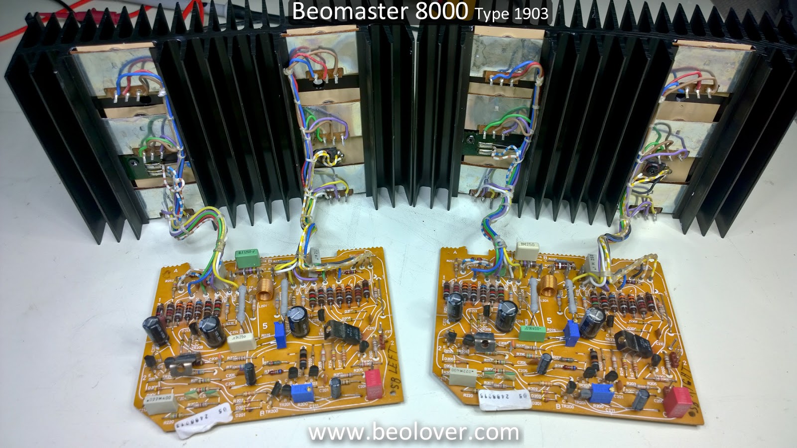
The output amplifier assemblies on the Beomaster 8000 are two identical boards (same Bang & Olufsen part number). One for the left channel and one for the right channel. Each board seems small enough where the restoration task should be quick and easy.  At least it always starts out that way in my mind.

Actually doing the restoration work takes a lot more time than that one would think.  Most of the time is spent cleaning off the old, white thermal paste  where the transistors are mounted to the big heat sinks.  In more recent restoration projects I have started to use Sil-Pads for the thermal insulation of the output amplifier transistors. It works well and eliminates the messy white paste.

During this step I replace the electrolytic capacitors on the output amplifier board as well as the no-load current trimmer resistor and DC offset trimmer resistor.  I also check the output transistors while I have them disconnected during the thermal insulator replacement.

Here are the left and right channel output amplifier boards for this Beomaster 8000 project.


It is a good idea to work on them one at a time so you always have a complete output amplifier board available as a reference.


There are only six capacitors and two trimmer resistors (both 100Ω max.).  Here is the output amplifier board prepared for its new parts. The two axial electrolytic capacitors measured half the capacitance value they were supposed to be.


Here is a test of one of the PNP Darlington transistors.


All of the transistors on this Beomaster's heat sinks measured good. Note that the hFE value of the Darlington looks low.  While this transistor tester is very good it cannot accurately determine the hFE of a Darlington transistor.

Now for the removal of the old mica insulators, the white thermal paste and the transistor components


The first set of output amplifier transistors are installed with new thermal insulation.


The PTC resistor on the second set of transistor components still gets a dab of white thermal paste for its insulation.


The newly mounted output transistors and heatsink are now ready to connect back to the output amplifier board.


Here are the completed left and right channel output amplifier assemblies ready for bench testing.


On to the bench test of these reworked output amplifier assemblies.

Monday, January 22, 2018

Beomaster 8000: Left & Right Channel Output Amp Boards

The actual component replacement on the left and right channel output boards (identical boards) is pretty simple. Just six capacitors and two trimmer resistors.  Most of the work is dealing with the messy thermal compound on the heatsinks.


The original mica insulators and thermal paste work very well. However, due to the removal and reinstallation of these assemblies being so messy I have been switching to sil-pad thermal insulators. They are very easy to use and do not require the messy thermal paste...which seems to get on everything.

Here are the two boards with the components removed from the left channel board. While the components are removed I clean off the old dust that has accumulated over the years.


Here are the recapped boards.


The original trimmer resistors for (no-load) idle current and DC offset are replaced with multi-turn, sealed trimmer resistors.

For this application I have started to use sil-pad sheets instead of precut pads for the transistors. The sheets can be cut to cover a larger area which is what I like to do on these heatsinks because the mounting of the transistors can result in the shifting of components.


Installation of the transistors on the heatsinks is done by starting at the bottom and working to the top. The metal spring clips that hold the transistors in place have to slide over the top side of the transistor. The transistors shift a lot during this process and the spring clips are a little tricky to get into place. You can imagine the mess to clean up when thermal paste is used.


Here are the completed boards.


The next step is to perform the initial no-load, idle current adjustment on these two boards. These output amplifier boards can be powered and adjusted outside the Beomaster if you have the proper bench power supplies.

Wednesday, January 17, 2018

Beomaster 8000: Power Supply Board Recapping

The Beomaster 8000 Power Supply board restoration consists of changing out several electrolytic capacitors along with a couple of tantalum capacitors with new 105°C capacitors. As I normally do I use WIMA MKS capacitors where the capacitor value is less than 10uF.

Here is the before picture of the power supply board.


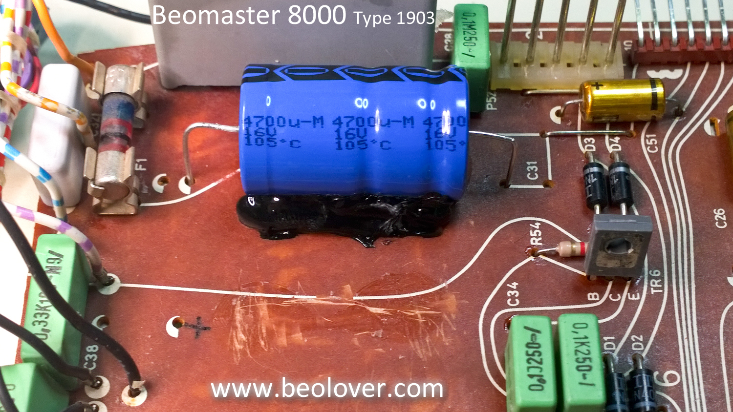
The capacitor replacement is pretty straight forward with the exception of one capacitor located inside the metal shield box on the board and the three large, axial capacitors (2200uF and 4700uF) that require some glue to secure.

There is also a separate heat sink assembly for three voltage regulators. I started with that assembly and replaced the lone 10uF capacitor. While I did that I decided to clean off the old thermal grease and change out the thermal insulators.


On the three, large axial capacitors I scraped off the old mounting glue to prepare for the new capacitors.


For this type of application a hot glue gun works great as the glue works fast and can always be removed in the future if necessary.


The metal shield box for the Beomaster remote control receiver is not too bad to remove but does require de-soldering four mounting tabs. Here is the box removed and the power supply board recapped.


The shield box is soldered back in place, the board connector solder joints are reflowed and this board is done.