Featured Post

Beolover SyncDrive: DC Platter Motor Replacement for Beogram 4002 and 4004 (Type 551x and 552x)

Late Beogram 4002 and the 4004 (Types 551x and 552x), which have DC platter motors instead of the earlier synchronous AC motors usually suff...

Showing posts with label fuse. Show all posts

Saturday, February 5, 2022

Beogram 4004 (5526): Return to Bench with Blown Fuse - Replacement of Solenoid Transistor

A Beogram 4004 (5526) that I restored in April 2019 just returned to my bench with blown fuses. I was told that "it died as I was lowering the tone arm and is now totally non-responsive".

This suggested an issue with 1IC4, the Darlington transistor that is responsible for regulating the current through the arm lowering solenoid. This solenoid is the largest current 'hog' of the Beogram and puts quite a bit of strain on this IC whenever the solenoid is activated.

But first I installed two tabs on the power entry plug for convenient connection of a bench supply for testing the board:

Then I extracted the TIP125 that was installed as 1IC4 and plugged it into my transistor tester. It gave me a strange reading with an additional forward direction diode between emitter and collector, while still showing a reasonable turn-on voltage of 1.09V for a Darlington.
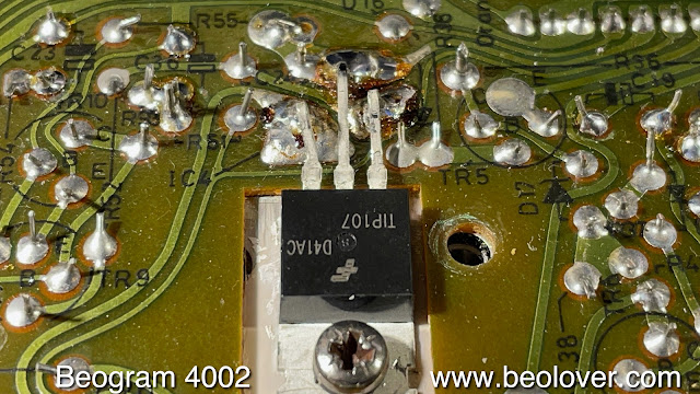
I think this shows the limitations of transistor testers...the new TIP107 replacement showed a normal reading:

I installed it 
and tested the deck with the bench supply providing power. All went normal and the arm dropped normally at the LP run in groove position.
I decided to also replace the other two power transistors that run the platter motor (1TR2) 
and the 24V rail of the Beogram (1IC1)
with a TIP120 and a TIP31, respectively, to be on the safe side.
I stuck a cartridge on the arm and put a record on the platter (Eberhard Weber Colours "Little Movements"  (ECM 1-1186), and it played as it should. So I think this Beogram may be fixed. I will give it some more play and then it will be time for it to return to its owner!


Thursday, February 4, 2021

A Pair of Beomaster 1900 Receivers for Restoration: Unit #1 Power Restored

The first of two Beomaster 1900 units sent for restoration is completed and ready for some testing.
To begin testing a restored Beomaster the work always begins with plugging it in to line power, turning it on and checking the power supply voltages.

With this Beomaster I was not getting any power.

In the previous post I suspected the +15 VDC power supply fuse (a 2A fuse) and the fuse holders that had burned spots on them. I also looked at the Beomaster 1900 mains power switch and found a wire exposed through the insulation.

I fixed the wiring on the main power switch.

The Beomaster 1900 has a nice way of securing the wire to the line voltage. It holds securely but it is easy to open up and work on.

There is a plastic wire holding clip that just slides out to loosen the wire.


I fed more wire into the Beomaster so I could cut off the bad section that had the exposed copper wire.
Then I wired the main power switch back up and put everything back in place.


That looks much better.

Next I changed the fuse holder for the +15VDC supply.

However, there was still no power. I could see now that I was getting proper voltage from the transformer to the bridge rectifier but no DC voltage out of the device. 

The reason I changed the bridge rectifier was because the Beomaster arrived with a pieced together diode bridge and I could see the charred remains of some past event involving power on this receiver.
There is nothing wrong with making a bridge rectifier that way but I wanted to return this Beomaster back to the way it originally was.

Here is the original state of the Beomaster 1900 +15 VDC power supply as I received it.


Here is the Beomaster 1900 with new parts: fuse holder, bridge rectifier and 2200uf smoothing filter capacitor.


There is no way the new bridge rectifier could be bad so I investigated my installation of it again.
Checking continuity of the signal paths on the trace side of the main circuit board I discovered that the solder pads for the bridge rectifier leads had two damaged pads. They didn't reveal their damage when I installed the new bridge rectifier but underneath they were not making contact with the trace on the board.

Here I show what happened when I pulled one of the AC voltage connections to the bridge rectifier.
The +VDC pad was also not making connection even though you could not visually see it.


I reworked the bridge rectifier connections and now it looks like this.


You will note that I also had to place a jumper on one side of the new fuse holder leads on the trace side.
This was required because the original two-pin holder clamp previously makes that jumper.
At first I thought that was the source to my power supply problem but after making that addition I still had no +15 VDC. 
There were still the two bridge rectifier solder pads that required repair.
As often happens in these repairs there can be multiple issues affecting one function. :-)

...and now there is +15VDC power on the Beomaster.
The transformer sends around 18 VRMS to the bridge rectifier whose DC output is around 23 VDC as shown on the meter below as measured across the smoothing capacitor.
That voltage then goes through a +15 VDC regulator.


Now I can finally move on to testing the Beomaster 1900 power supplies and make some service manual adjustments.

Sunday, January 31, 2021

A Pair of Beomaster 1900 Receivers for Restoration: Unit #1 Reassembly for Testing and a Power Problem

 The next step before testing the Beomaster 1900 was to reinstall the four output transistors that mount on the rear heatsinks. I had removed the heatsinks and the original thermal insulating paste. On the reassembly I like to use modern SIL-Pad thermal insulators. They do a great job and don't have the mess that thermal paste does.

Here are the parts laid out for reassembly.


I like the way Bang & Olufsen chose to mount the transistors to the heatsinks. They use curved, metal spring clips that press the plastic face of the transistor against the heatsink...sandwiching the thermal insulating material in between.

Here are the output transistors reinstalled.


Everything is installed that is necessary to start testing the Beomaster 1900.

It only took the amount of time for me to connect up the variac and dim bulb tester to try powering up the Beomaster to discover a problem.

The Beomaster 1900's +15 VDC power supply was not turning on. No Standby lamp illuminated.
I exercised the main power switch again to make sure it wasn't dirty but nothing.

I unplugged the power cord and started to check around the +15 VDC power supply.  I could not measure anything across its fuse.  I had noticed the fuse holders were badly tarnished but this unit had powered up prior to starting the restoration. I pulled the fuse and it was okay. I just couldn't get anything through it from the fuse holders.

Here are the fuse holder clips and where I removed them from on the board.


Age has not been kind to these fuse holders. I remember now that the original bridge rectifier had been replaced on this Beomaster and there was a large, charred mark under where the bridge rectifier had been mounted. It is likely some big power event had occurred sometime in the past.

In any case I need to order some of these fuse holders on the +15 VDC power supply line.  If I order them today Mouser will deliver them on Tuesday.

The power supply incident got me thinking about all of the input power to the Beomaster 1900. I had seen a bad power switch on a Beomaster 2400 in the past so I should look at this one more closely.

I am glad I did. The switch actually measures good and I did some cleaning on it with Deoxit.  However, I found a cut in the insulation on one of the main power wires delivering line power to the Beomaster.  It probably wouldn't hurt anything but I don't like bare wires where they are not supposed to be.


I will rework the wiring on the power switch and fix that problem while I am waiting for the fuse holder clips to arrive.

Here is the cleaned up and prepared power switch.


Thursday, February 22, 2018

Beomaster 6000 (2702) restoration: mounting the power supply into the main chassis

After my disaster with the electrostatic discharge that fried several transistors in the output stages (click here), it was now time to put everything back into the main chassis of the Beomaster 6000. I had not touched them yet since the dismantling, so it all looked kind of dirty !


And after cleaning


And yes, I like to keep the stickers & lettering on it to keep the look & feel of vintage...

The 4 rubber feet had there best time, so I replaced them with 4 spare better looking ones.


The transformer went in first after adding a new power cord to the on/off switch. Then the voltage selector was mounted with the 2 screws. The small metal frame with the bridge rectifier and the stabiliser transistor are fixed. The larger clear metal frame was put in place, the on/off switch mounted and the plastic safety cap plugged on top.


The plastic holder with the two main fuses was screwed on again, but the copper foil did not stick anymore to the chassis. Not sure what type of glue they used because it's supposed to be electrical conductive. So, I used some duck tape to keep it in place and connected.


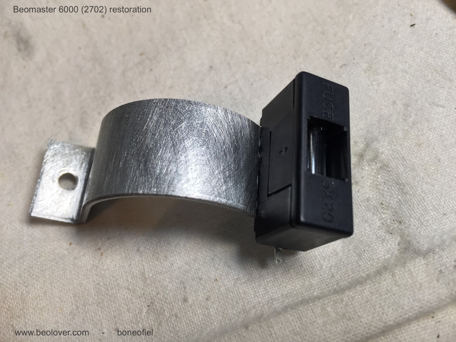
As mentioned in one of my earlier posts, some of the later Beomaster 6000's have an extra fuse (4A slow) mounted in the 27V AC connection from the transformer to the power supply PCB as an extra protection.  


I decided to add one also in the same spot. I used a encapsulated one versus the "open" one as seen in the picture above.

I needed to modify the metal bridge, that holds the power capacitor, a bit and drill a hole in it.


The transformer, main bridge rectifier, voltage selector, main fuse holder, on/off switch, power caps and new fuse are now in place.


Wednesday, February 7, 2018

Beomaster 8000: Replacing the Processor Crystals

A Beomaster 8000 that I restored a few years ago for an Australian customer unfortunately had to come back to my bench due to a malfunction of the processor board. It exhibited rapid-fire power on/off events, which are a sign for a dead crystal on IC4 (slave processor). See here for more detail on how I first ran into this issue on the 8000 that is in my living room. Anyway, here are a few pictures of how I fixed this one. This shows the original setup:
As you can see someone in the past soldered jumper wires directly to the pins of the microcontrollers (savages!) to bridge the often failing vias that connect some of the processor pins to other components on the board. I usually re-solder the vias instead of putting in jumper wires. The reason that these vias fail is poor initial soldering. In the 80s electronics manufacturing just started becoming fully automated and some outcomes were not as high quality as one would desire...

Anyway, here I had to deal with these wires since it is good practice to take the microcontrollers out before replacing the crystals. They can be charged with high voltages when you take them out of the packaging, and this can fry the ICs...and that essentially would mean that a donor Beomaster 8000 would need to be procured. I was able to remove IC3 (right) without trouble but IC4 on the left was stuck. When the wires were soldered on a lot of solder was used and some of it penetrated the lower regions of the socket. I unsoldered the affected legs of the socket and then pulled the IC out. It came out including the three soldered-on pins from the socket. Once it was out it was easy to clean the pins up since I was able to get to the solder without having to heat everything for a dangerously long time...much better for the survival of the precious IC.

I implanted a new IC socket
And then exchanged the crystals and oscillator capacitors (the original ones are 12 pF while the modern crystals need 18 pF caps):
I elected to not solder the jumper wires back on to IC4. Instead I fixed the vias. I left the wires on IC3 in place since every time one heats up a pin on an IC there is a slight chance that damage can occur...

Once it was all back together, I fired the Beomaster up for the first time, and it came on normally, no more relay rattling etc...so I hope this did the trick.
Beolovely!


Tuesday, December 27, 2016

Beocord 9000: Power Supply

 Moving on to the Beocord electrical problems I started with the power supply.  The power supply in this unit was having problems. I wasn't measuring +24 VDC on capacitor C1.  At first I suspected the rectifier board so I pulled it and examined the supply capacitors (C1, C2 and C3).  Here is the rectifier board in the Beocord 9000.


Here are the C1 through C3 measurements.


I decided to swap some parts with other Beocord 9000 units I have on hand. This Beocord's rectifier board worked fine in another, working Beocord unit I have so the board is fine. That led me to the transformer. Sure enough, the transformer was the problem.
At first I thought the transformer was defective so I started checking other Beocord 9000 units I have...both working and non-working. I found another one with a non-working transformer and compared the Beocord serial number to the one I am working on. What a surprise! I had another Beocord 9000 unit that was an assembly line mate to the current Beocord I am working on. What are the odds of that? After all of these years these two meet up on the same workbench.


The transformer turned out to be a non-issue as I remembered the transformer assemblies have an internal 250V, 0.5mA fuse inside. I opened up both transformers and sure enough, the fuses had blown.


This resolved the Beocord 9000 power supply questions. Now it is on to figure out why the unit will not come on.

Friday, October 7, 2016

Beomaster 8000: Rattling Main Relays and a Broken 2MHz Oscillator Crystal

*********************************************************************************
ACHTUNG: Please, note that the crystal exchange procedure described here can damage the microprocessor chips on the uProcessor board. It is recommended to remove the chips before replacing the crystals and the capacitors. Due to the inherent capacitance of these devices, high voltages can be present between their terminals, which upon release, can burn out the gate that forms the oscillator together with the crystal. Make sure you short circuit the leads of the parts before installing them.
*********************************************************************************


Oh well, nothing lasts for ever!...The fully restored (2011) Beomaster 8000 that I am using in our living room recently broke with a rather strange fault. I woke up at 4 am in the morning to the beeping of an uninterruptible power supply (UPS) in distress. First I thought we had a power outage, but it turned out that the UPS turned itself off due to a malfunction in the connected Beomaster 8000 (I run all my B&O equipment on UPSs to reduce the risk of damage from grid voltage spikes and the like). I restarted the UPS and immediately the main transformer power relays of the 8000 started going on/off in rapid sequence. And then the UPS caved in again, turned itself off and started beeping again. This immediately pointed to a severe fault in the 8000 since a UPS only shuts down if the current drawn exceeds the rated 10 or 16 amps. This suggested to not try running the Beomaster again before having a look inside.

I shut everything down and went back to bed. The next morning I swapped the 8000 out with one of the other 8000s I have around the house in less important locations. A few days later I opened the malfunctioning unit up and ran it. First everything was normal but after a while it started to rattle again. I switched it off immediately and started wondering what might cause such behavior. First I thought there is a problem in one of the outputs triggering the protection circuit. The reason was that I initially detected 15V at the output of the protection circuit (collector of 6TR15) during relay rattling phases. The 15V pull up the base of 6TR11 via 6D12, which then causes the relays to go off, cutting power to the main transformer. This is usually caused by malfunctioning output transistors or overheating of the outputs. However, in this case the 15V were rather a consequence of an entirely different root cause.

After some playing around with the unit and enjoying a few more UPS shutdowns and relay rattling events, I finally figured out that the crystal oscillator of 9IC4 on the main processor board had some issues. I figured this out due to two phenomena:

1) After one of the rattling episodes I was not able to turn the Beomaster back on. The standby LED was lit, but no more reaction to the keypad. Panic ensued since I thought I had accidentally fried the processor or some other disastrous event occurred. So I did a processor self-test by pressing the Monitor key first and then additionally the on/off bar on the keypad. This initiates a self-test sequence. And I finally saw my first error code on a 8000: TE8!
The manual yields a rather cryptic cause for this error:

"Error TE8:    Defect IC:9IC4(RAM)      Or short pin to chassis: 10-11"

Initially I thought I had really fried the slave processor that is responsible for the relays...but then ,after my initial panic subsided and normal brain functions kicked back in, I thought that my maxim "silicon usually dies last" should apply here too, since even a complete main power supply failure and dramatic short circuit etc...would have a hard time killing anything on the processor board. There is simply no direct connection. Furthermore, when I tried to turn the unit on again after an hour or so, it worked normally again indicating a healthy state of affairs on the processor end of things (silicon either is alive or dead...rarely there is an intermittent state in my experience). Also, once it worked again, the error code went away and I got this from the self-test:
A happy Test Passed (TP).

2) The second indication toward the oscillator issue came from an oscilloscope measurement I made after the error code episode:
The probe was hooked up to the base of 6TR11, which is connected to Pin 16 of 9IC4 via some resistors. At this point the unit was working and there was no rattling from the relays at all. But you see some type of digital random oscillation of the signal that normally should be just near-0V when the unit is on. The digital character of the signal already suggested to me that there might be a processor issue...I watched this for some time and then it changed to a more aggressive behavior:
A much stronger deviation from 0V and still pretty random and close to switching 6TR11! And then it went completely crazy and the relay clicking started again as 6TR11 did its job. I did not save the measurement at that point since I was busy turning off the unit as fast as I could...;-). This finally put me on the right track, however, and I started looking into 9IC4. The same random signals were also directly visible at Pin 16 of 9IC4, just on a 0-5V scale since at Pin 16 we are directly at the source of the signal and there are no resistors over which the voltage drops. This told me that indeed the processor was going 'crazy' occasionally. This combined with the error information above that alternatively to a processor malfunction also Pins 10-11 could be 'grounded' finally made me see the light since the oscillator crystal is connected to Pins 10 and 11!

I wiggled the crystal a bit and indeed, I was able to cause the Pin 16 signal to change from completely quiet 0V to the above shown random signals and to 'crazy' causing relay rattling. So I guess what happened was that the clock of the processor started to have random hiccups causing timing issues while processing its firmware, which then caused the normally constant output at Pin 16 to become random triggering the relay circuitry.

I ordered a few 2MHz crystals from Newark (21M6819) along with matching 18pF resonator capacitors (46P6436) - the original crystals run on 12 pF capacitors, i.e. they need to be exchanged along with the crystal to get a proper oscillator signal. After a few days I received the parts and put them in. This shows the original crystal with the two capacitors (brown, right below):

This shows the board with the parts removed:
This is the new smaller crystal in comparison to the original one:
Like most components modern ones are considerably smaller than the original ones...and this finally shows the new units implanted (I also exchanged the 9IC3 components assuming both the original crystals were from the same batch...;-):
The exchange is straight forward, but the right capacitors are difficult to remove since one of their legs is fed through a hollow via, which is a bit of a pain to unsolder due to the very small space between lead and via insert. One has to hold the solder tip to the via to liquefy the solder and then pull the cap out...three hands would be great for this process...;-)

One more thing: It is crucial to cut the leads on the solder side of the board very short to prevent short circuits to the EMI can that encloses the processors:
I had them too long initially, and I got some really spectacular readings on the displays when I turned the unit on. Essentially, it became completely unresponsive showing some random zeros on all of the displays. Another near-heart attack...;-). Cutting the leads solved that problem...live and learn...;-) 
I am running the unit now for a couple days back in the living room and it seems the issue has gone away. Also wiggling the crystal did not cause the issue anymore. So I am assuming we are back in business with this lovely Beomaster 8000!

Remarkably, a few days after this happened to my 8000 I received an email from an Australian customer whose 8000 I restored a couple years ago telling me that his Beomaster developed the exact same symptoms (I am sending him a couple crystals and the capacitors plus some instructions...this is Beolove!).
So I am thinking that exchanging the crystals should become a standard part of any Beomaster 8000 restoration...two at the same time is a rather strange coincidence, which points to a systematic issue with these crystals. Probably the leads are delaminating from the crystal material after 30-35 years...
Time to get back to my other restoration projects!