Featured Post

Beolover SyncDrive: DC Platter Motor Replacement for Beogram 4002 and 4004 (Type 551x and 552x)

Late Beogram 4002 and the 4004 (Types 551x and 552x), which have DC platter motors instead of the earlier synchronous AC motors usually suff...

Showing posts with label 2018FL08BM8000. Show all posts

Tuesday, February 5, 2019

Beomaster 8000 From Canada: Packing for shipment home

The day finally arrived to ship the Beomaster 8000 from Canada back home. All tests have passed and loose end tasks completed.

This receiver is quite heavy. The packed shipping weight can be from 57 pounds to 65 pounds depending on packing materials. I was able to get this shipment prepared at 57 pounds in a 30 inch x 20.5 inch x 12 inch box.

I glue the bottom flaps of the cardboard box together with a common wood glue.
After that I lined the bottom and sides with 1 inch thick, 2.2 pound rated, polyethylene foam. Those pieces are attached using 3M Super 77 spray adhesive. Polyethylene foam has some give to it but is sturdy enough to resist puncture. A good material for the first line of defense.


The old type styrofoam and styrofoam peanuts are the absolute worst packing material ever devised. They should never be used!
They generate a lot of static electricity and small pieces get into everything...especially the audio component you are shipping.

Bubble wrap is not very good either. It is okay for small, light things but heavy shipments can puncture the bubble wrap leaving no protection at all.

For this Beomaster 8000 my first step in wrapping it up for placement in the shipping box is to place it inside a clear plastic bag. That will protect against any liquid and keep packing materials from rubbing directly against the Beomaster.


Next I use 1½ inch thick eggcrate foam to wrap the Beomaster providing another layer of padded protection. This foam has more cushion than the polyethylene outer foam. I do one wrap lengthwise and one wrap crosswise.


The eggcrate foam wraps are taped and everything is placed into the shipping box. I use extra blocks of the polyethylene foam to fill in any gaps.


The last rectangular piece of polyethylene foam is the lid followed by taping shut the cardboard box.


This Beomaster 8000 receiver is now on its journey back home and I hope to hear happy results from the owner after it arrives.

Sunday, January 27, 2019

Beomaster 8000 From Canada: Taking care of some loose ends before shipping home

The Beomaster 8000 receiver from Canada that I blogged about here has been undergoing extensive testing in my listening room.  The input sources (FM, phono, tape 1 and tape 2) have been exercised for countless hours. This unit has performed great.

When it was time to unplug the Beomaster from my Beosystem 8000 listening room setup I got a surprise when I unplugged the Beogram 8000 cable. The Beomaster 8000 Phono DIN jack came out with. Part way anyways. The wires in the Beomaster source input connector box kept the DIN jack from getting too far.

I hadn't noticed any problem with the Phono DIN jack previously but now that is was out I could see that one tab (of two) that prevents the DIN jack from pressing into the connector box was broken and both side tabs, that keep the DIN jack from pulling out, were broken.

Here are the pictures.


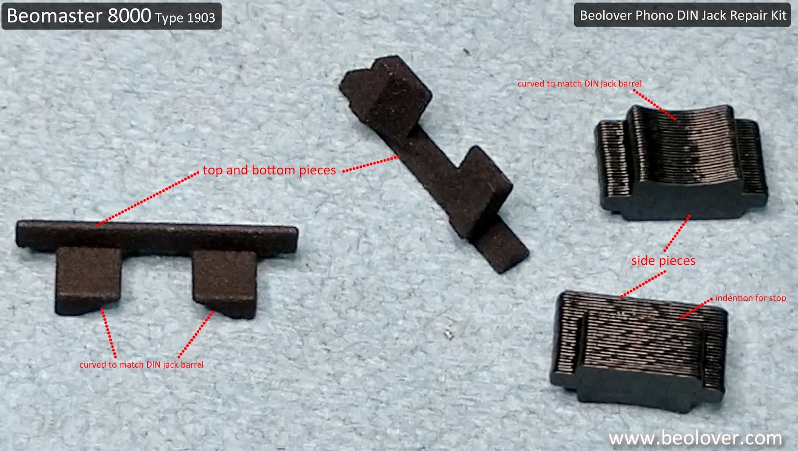
Fortunately for this type of problem Beolover makes a 3D printed repair kit.


I had used the 3D printed parts for the top and bottom edges of the phono DIN jack on the Beomaster 8000 from Texas.  That DIN jack had intact side clips though so the top and bottom Beolover parts were all that were needed on that project.

This Beomaster 8000 phono DIN jack had its bottom tab intact but was missing the top one. In addition, both the left and right side clips were broken.

The next two pictures show the installation of the phono DIN jack left side stop piece. The original side clips were a flexible, spring like plastic tab. A replacement part that works as a spring clip isn't really an option. Beolover came up with side pieces that glue to the DIN jack housing in such a way that the DIN jack cannot be pulled out (the top and bottom replacement pieces are designed to not let the DIN jack press down into the connector box).


Note that just one side (the left side) was installed first. Since this DIN jack still had its original bottom tab I only needed one of the Beolover parts for that part of the assembly.

With the left side stop piece glued in place and the top Beolover replacement part installed I was able to push the phono DIN jack back into the source input box.

The final step was to glue in the right side stop piece.


The phono DIN jack was now securely mounted where it will no longer fall in or pull out of the source input box.

Here is the completed repair.


Now back to another round of listening tests before the packing up for shipment back to Canada.
That step cannot be skipped. Whenever working with the source input connectors it is really easy for one of the small wires to break.  I do not want to risk shipping this Beomaster back to Canada only to discover there is some problem I could have easily caught with a little more testing.

Wednesday, November 28, 2018

Canada Beomaster 8000: Checking out the reworked boards

In the last post on the Canada Beomaster 8000 I left off having completed the restored display board.  With that last board completed I can finally begin testing what this Beomaster can do.

Since it has been a week since I last checked this Beomaster restoration I decided to recheck all of the power supply voltages, the no-load current checks and the DC offset checks.


Naturally I tested the display board now that it is reinstalled.


Everything looks like it is working correctly so I test played an iPod Nano into the Beomaster Tape 2 source input. As usual I connected my Beovox S-55 speakers I keep in the lab.

The Beomaster sounds like a Beomaster 8000.

I wrapped up the day by preparing the Beomaster for some upcoming performance tests.
Here is my test setup.
I am applying a 1KHz sine wave of 1.0VRMS to the Tape 2 source input of the Beomaster. I will measure and monitor the voltage across the dummy 8Ω speaker loads as well as measure the output with a QuantAsylum QA401 Audio Analyzer.


The test setup is ready and I ran a couple of preliminary tests.


Later this evening I will start running the performance tests.

Tuesday, November 20, 2018

Canada Beomaster 8000: The display board is ready

The display board out of the Beomaster 8000 from Canada is completed now. It was the final piece before starting the functional testing phase of the restoration project. Once this board is installed back in the Beomaster I will recheck the power supply voltages and the output amplifier assemblies.

After installing new smd LED devices in the segmented display assemblies and bench testing them I sealed the display modules back up and checked them one more time on the bench.


They look much nicer now that no stray light is able to get out.

Before I installed the segmented displays onto the display board I changed out the four indicator lamps on the board with four Beolover LED indicator assemblies. The change to the Beolover LED indicator assemblies requires the removal of four 220Ω resistors on the display board (R34, R36, R38 & R40). They are highlighted in the picture.


Now the display board can be reassembled for installation back in the Beomaster.


Saturday, November 17, 2018

Canada Beomaster 8000: Rebuilding the displays

I have the new smd LED components installed in the Beomaster 8000 segmented display boards and I am running a burn-in test on them.

It is a little difficult to capture (in a photo) what the rebuilt displays look like without the top lens cover on but the purpose of this test is to make sure all of the segments work. I usually run this burn-in test for twenty-four hours. That gives the new components a decent amount of time to fail if they are going to. I would hate to bundle everything up then have to disassemble the displays again.


To get to this point I removed the display modules from the Beomaster 8000 display board.


There are white and red tabs on the rear of the display board modules that hold the light guide and lens cover in place. Those tabs were originally part of the plastic sub-assemblies and melted down to secure the full display assembly. Since those cannot be removed and reused I have to just cut them off and use a different way to re-assemble the display modules after I rebuild them.

Here is the channel balance display board with the light guide and lens cover removed.


You can see these Bang & Olufsen display modules were very custom and the tiny, smd-like LED components cannot be replaced. We could locate the LEDs that have failed and just change those. However, that would result in a noticeable difference in the red illumination because the new smd LEDs are not exactly the same as the originals. They are very close but not the same. So it is best to change all of them. Another equally good reason to change all of the LEDs is because you can bet that if you only changed the failed LEDs the remaining good ones will likely fail as well. It's definitely better to get everything done while the Beomaster is open.

Here are some pictures from previous Beomaster 8000 display repairs that I use as a reference for this task.

This first picture shows the new smd LED component next to the original B&O LED.


This picture shows identifier markings on the replacement smd LED component for reference.


The next step in the display rebuild after removing the light guide and lens cover is to cut out the original LED component.


I gathered a number of my Bang & Olufsen display modules that I have been wanting to rebuild and hope I can take the opportunity, while I am display repair mode, to get them done as well.

To prepare each display board for the new smd LED components I cut off the small solder pad that the original LED cathode rested on. That makes the gap between the anode and cathode pads better for the new components.


It is important to "tin" the solder pads before mounting the smd LED components. That will ensure a good, reliable connection.


Now for the actual mounting of the new smd LED components.

I have to say that this task is one of the most time consuming restoration tasks and requires a lot of patience to handle the smd LED devices while soldering them in place. The technique I use (and recommend) is to mount the smd LED components just on one lead. The reason is because the LED component must fit just right in the plastic light guide of the display module. There are always several LED components that I have to reposition slightly to correctly function inside the light guide. That also means the soldering process is to first position the smd LED with tweezers, solder one side to secure it, check the fit with the light guide, reposition if necessary and finally, solder in the other side. Quite labor intensive and hard on the eyes.

Here is a fit check of the smd LED in the light guide.


Once all of the new LED components have been fit checked I finish soldering the LEDs to the board.


Here is the completed FM tuner frequency display board.


On to the remaining three modules.

Another tip is to have a reference picture or (even better) a spare display board to use as a reference when mounting the new LED components. This task is very tedious so be disciplined to check the polarity carefully with each LED mounting.  It is also another good reason to only solder one side initially.


Here is the completed LED replacement on the Beomaster 8000 selected source display board.
Note: The glare from my lighting off the no-clean flux residue makes a couple of the solder connects appear shorted.


The volume level display board is next.


Finally the channel balance display board. This board is the easiest to position the smd LED components on because it doesn't have pads where the LED mounts. However, the narrow trace makes soldering in the LED components a little tricky and this board is usually the one to have a connection problem.


Once the twenty-four hour burn-in test is complete I can reassemble the four display components and wrap up the display board. Then it will on to functional testing with this Beomaster.