Featured Post

Beolover SyncDrive: DC Platter Motor Replacement for Beogram 4002 and 4004 (Type 551x and 552x)

Late Beogram 4002 and the 4004 (Types 551x and 552x), which have DC platter motors instead of the earlier synchronous AC motors usually suff...

Showing posts with label plug. Show all posts

Thursday, May 24, 2018

Beogram 4004 (5526): Installation of A New Output Cable

After replacing the light bulb in the sensor arm with an LED assembly it was time to look into the RCA plug 'conversion' of this Beogram 4004 (5526). This shows the output cable in the condition when I received this Beogram:
Not a very inspiring sight. The blue and yellow leads are the Beolink signal lines that allow controlling the 4004 via a Beomaster 2400. We decided to return this 4004 to its original DIN7 output scheme. Originally the 4004 came with a convertible male DIN7 plug, which can be turned into a standard DIN5 by unscrewing the two pins that are extra in the DIN7 format. This shows a plug as seen on a 4004 I restored a few years ago:
The two outer pins were removed so that the plug essentially acted like a standard DIN5 phono output. Unfortunately, such DIN7 plugs are not available anymore. A solution I came up with is to install female DIN7 plug that has all the signals on it. If extended with a DIN7 cable it turns into a DIN7 male output that will properly work with a Beomaster 2400. Extend it with a DIN5 or a DIN5-to-RCA adapter and a standard non-B&O phono output is achieved.
This shows the female DIN7 plug during the installation:
Note that the leads need to be soldered in a mirrored pattern compared to that applied for a male DIN7 plug, since male-male DIN5 and DIN5-RCA jumper cables mirror the leads for symmetry reasons.

This shows the DIN7 connected to a DIN5-to-RCA jumper cable:
The system ground connection is on a separate wire (not visible on this photo) that it can be connected to the GND terminal of the RCA input amplifier.


Saturday, March 17, 2018

Beogram 4000: Upgrade of Signal Path with New DIN5 Plug and a Grounding Switch

As usual the original DIN5 plug on the Beogram 4000 that I am currently restoring was badly oxidized. This shows the original plug:
I replaced it with a new all-metal plug that has gold coated terminals:
Another useful upgrade of the signal output of any Beogram is the installation of a switch that allows connecting signal and system grounds. This is a useful feature if the Beogram is ever to be used with a DIN5 to RCA adapter. Since RCA cables do not carry the system ground, connecting it to the signal ground on the Beogram often eliminates humming. This shows the output terminal assembly of the Beogram 4000 in its original condition:
This open layout makes it very convenient to add a switch:
The shown switch position connects the two ground. Flipping the switch would open the connection.


Friday, June 9, 2017

Beogram 4004 (5526): Replacement of Convertible DIN7 Plug with DIN7 Socket and an RCA Adapter Cable

Any restoration of a Beogram should include the replacement of the DIN connector to ensure a low impedance signal path on the way to the amplifier. In the case of a Beogram 4004, the DIN connector is a convertible male DIN 7 plug, where the two additional pins can be unscrewed from small sockets. These two pins would carry the remote control signals from a Beomaster 2400, which is designed to control the 'start' and 'stop' operations of the Beogram 4004. An early form of Beolink, so to speak. But of course, if one does not connect to a 2400, these pins are not needed, hence the convertibility. This shows the plug with the empty two sockets at the ends of the 5 pin half-circle:
This type of plug is no longer available, and so I resorted to replacing it with a DIN 7 female socket, which then connects to a jumper cable with the desired number of pins or RCA termination. In essence this approach converts the Beogram 4004 output scheme to that found in the later Beogram 800x models, who have a DIN 7 socket mounted in the back of their enclosures. That way one can connect with both DIN 5 and DIN 7 jumper cables to a non-B&O or B&O amplifier.

Even cable mount DIN 7 sockets are difficult to find these days, but Steve at soundsheavenly.com can provide them. Here are a couple impressions: This shows the socket soldered on:
and with its shield in place:
And finally with a DIN 5 to RCA adapter cable:


Thursday, June 8, 2017

Beogram 4004: Replacement of Convertible DIN 7 Plug with a Female Socket and Adapter Cables

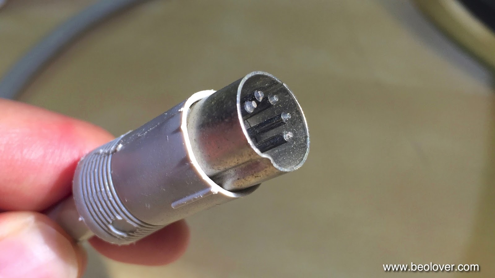
While enjoying the Beogram 4004 that I recently restored I was looking for an adequate modern replacement for its convertible DIN 7 plug. This plug is a special design that does not seem to be made anymore. Here is a picture of its business end:
The picture shows the plug in its DIN5 configuration, i.e. it can now connect with any standard DIN5 amplifier input. The two (threaded) orifices above the pins can hold two more pins, which can be bolted in if the Beogram is to be connected to a Beomaster 2400 to take advantage of its remote control, which can be used to start/stop the Beogram. In essence these two additional pins carry the remote control signals for the Beogram. But, of course, since this is a male plug, the pins have to be removable if the Beogram is to be used in a standard DIN 5 setting.

Sadly, these plugs are nowhere to be found these days, and so, if a new plug is desired, another approach needs to be found to preserve the above 'convertibility'. My solution was to replace the plug with a female DIN 7 socket. That way DIN5 (or DIN5-to-RCA) jumper cables can be used for non-B&O set-ups and DIN7 jumpers can be used to connect to B&O setups. In essence, this modification gives the Beogram 4004 the same connectivity design like the later Beogram 800x, which have a panel mount DIN7 socket in their back panel to receive a suitable jumper cable.
It was pretty difficult to find a decent female cable mount DIN7 socket, but finally Steve at soundsheavenly.com saved the day by providing me with a few DIN7 Deltron sockets for cable mounting.

Here are a few impressions: This shows the socket installed. The red and white leads are the signals and the yellow and blue leads carry the remote control.
It is important to note that the signal leads on a female sockets need to be soldered to the other side of the connectors since male and female plugs have mirrored pin assignments to properly maintain the signal chain through the connections. This shows the fully assembled socket:


This is how it looks with a DIN5 jumper cable (also provided by Steve) plugged in:
This Beogram 4004 is finally ready to be shipped back to its owner!


Wednesday, June 7, 2017

Beogram 4000: A New DIN 5 Plug and Installation of a Grounding Switch

The Beogram 4000 that I am restoring right now had a badly corroded and poorly installed DIN 5 plug. Obviously not the original plug. Here are a couple pictures of the sorry state of this plug:
I think the dangling black lead may have been an attempt to reduce some humming issues (no surprise, considering the way this plug was installed...;-). Besides this strange construction, one of the signal leads was also disconnected due to a sad soldering job. 

I cut off the plug and prepared the leads for the new plug:
This picture shows the advantage of DIN connections over RCA: The entire cable and connectors are double shielded. Each lead is shielded by the signal ground lead and then there is an outer shield that connects the enclosures of amplifier and turntable. That way the shielding is complete, which gives the best defense against EMI. RCA usually only have a single shield via the signal ground. That is why there is usually a separate wire that connects the amplifier and turntable system/enclosure grounds.

Then I soldered it on:
And this is how it looks with the shield on:
Beogolden I'd say!

The final step of refurbishing the signal path was to install a switch that allows connecting signal and system grounds. This is a convenient features if there is a hum when connecting to RCA inputs via an adapter.
Switch to the left (as shown) and the grounds are connected. Switch to the right and the grounds are disconnected as in the original configuration. 


Thursday, April 20, 2017

Beogram 6000 (5512): Replacement of a Corroded DIN5 Plug with a New Gold Plated Unit

Practically all Beogram 4002/4 and 6000 need their DIN5 plugs replaced due to various levels of  corrosion on the contacts, which were not gold plated back in the 1970s. This Beogram 6000 (5512) is a 'beautiful' example:
and with the shield removed:
I cut the rusty plug off and installed a new gold plated all metal plug:
and with the shield on:
Beolovely! The CD-4 preamp board is next!


Sunday, January 29, 2017

Beogram 4000: Replacement of Corroded DIN5 Plug and Installation of a Grounding Switch

After rebuilding the control cluster the next step of my current Beogram 4000 restoration was to replace the original corroded DIN 5 plug with a modern gold plated all-metal plug, and to install a switch that allows connecting system and signal grounds in case there is a ground loop causing a hum in connection with the amplifier. This shows the rusty original plug:
And here the replacement:
Pretty! On to the grounding switch. This shows the terminals where the DIN cable is connected to the internal cartridge wiring:
This is the perfect spot to install the switch:
This switch allows to toggle between the B&O-original setup, where signal and system grounds are kept separate, and a configuration where both grounds are connected. B&O actually adopted this configuration in later 4002 and the 4004 Beograms. My experience is that if there is a hum, this connection in most cases suppresses it.


Wednesday, October 19, 2016

Beogram 4002 (5501): Replacing the Original DIN5 Plug with a Modern All-Metal Gold Plated Unit

No restoration of a 4002 is complete without replacing the usually oxidized original DIN5 connector. Those precious low voltage signals deserve the best contacts possible. Gold does not oxidize, and therefore it is able to make low-resistance and long lasting contact. This shows the original plug that was on the Beogram 4002 (5501) that I am currently restoring:

I cut the plug off and prepared the cable for installation of the new gold plated all-metal plug:
Then it was time to solder the plug to the cable:
And this shows the assembled new plug in all its glory:
Beautiful! On to the final touches to get this Beogram ready for primetime!


Friday, June 3, 2016

Beogram 4002 (5503): Installation of a New All-Metal DIN5 Plug with Gold Plated Contacts

In my opinion no Beogram 4002 restoration is complete without replacing the usually corroded original output plug(s) with modern all metal units with gold plated terminals. Those precious analog signals deserve only the best! Here are a few impressions of the DIN5 replacement that I just did for the Beogram 4002 (5503) that I am finishing up:

This shows the original DIN5 plug:
This shows the soldering job 'under the hood':
A proper DIN5 installation requires that the shield is separated from the signal ground and that the insulation of the signal leads extends to the solder terminals. All this can be a bit fiddly due to the small space and thin leads one works on. 
This shows the new plug closed up:
Pretty, isn't it?? This is Beolove!


Saturday, April 30, 2016

Beogram 4002 (5514): Installation of a New DIN5 Plug With Gold Coated Terminals

The Beogram 4002 (5514) that I am currently restoring is making progress. In my opinion a Beogram restoration is only complete with a modern all-metal DIN 5 plug that has gold coated contact terminals. The original plugs are usually corroded and that is not a great thing for transmitting the precious signals from the MMC cartridge. Here is an impression of the original plug with oxidized terminals:
This shows the soldering job inside the new plug:
And here the final result:
Pretty, isn't it?? This is Beolove! On to adjusting the platter and sub-chassis...


Tuesday, April 26, 2016

Beogram 4002 (5513): Installation of New DIN5 Plug with Gold Plated Pins

The restoration of the signal path is only complete with a gold plated plug, and so I just did it for the Beogram 4002(5513) that I am restoring right now: This shows the sad original oxidized plug:
And here an impression of the internal configuration of the new Rean plug:
Well organized and pretty! And with the all metal enclosure on:
Even prettier! This is Beolove!


Wednesday, March 9, 2016

Beogram 4000: A New DIN 5 Cable and a Grounding Switch

The Beogram 4000 that I am currently restoring had a cutoff output cable:
This is already the third 4000 that I am working on that had a mutilated cable. I really wonder why some people are attracted to cutting off cables...very strange! Anyway this gave me an opportunity to install a modern cable with double braided and foil shielding, which is the best way to keep interference from our precious MMC signals on their way to the amplifier.
I installed a quality Neutrik gold plated all-metal DIN5 plug on the business end of the cable:
I always like the looks of these plugs!

Here is the other end inside the turntable. First I prepared the cable for installation:
and then I soldered it in at the terminal block. This shows the original setup with my standard grounding switch already installed. This switch allows to connect signal and system grounds in case a RCA adapter without grounding breakout is used:
This shows the set-up with the new cable:
All good again in the 'signal path department'! Platter alignment and floating chassis adjustment are next!


Saturday, January 16, 2016

Beomaster 4000 (2406): AC Current Measurements in Transformer Secondaries

This post is a first update on the transformer issue that I identified in a Beomaster 4000 that is in an outstanding cosmetic condition otherwise (i.e. worth fixing!).
I recently entered discussions with a custom transformer manufacturer, and naturally the question of current in the windings came up. The Beomaster 4000 has two secondary windings, one delivering 47V AC RMS and the other 22V AC RMS. The service manual specifies a 275VA transformer, but makes no reference to the distribution of power among the two windings. This shows the pertinent part of the circuit diagram:
The 47V winding directly powers the output stages, while the 22V winding takes care of the rest of the unit such as the preamplifiers and the FM section.

In order to measure the current in each of the windings I added 0.18 Ohm shunt resistors in series into each of the circuits. This shows the measurement on the 22V section. The black and white AC lines connect to the far right back corner of the Beomaster where the rectifier sits:
I unsoldered the white lead and put the resistor in series:
Then I hooked up a voltmeter across the resistor and turned the receiver on with speakers connected. The voltages that I measured were a constant 30 mV for all settings except phono, where I measured 36 mV AC RMS. These results were independent of the volume setting. Even with white noise on the FM section or a 1000 Hz test tone on the Tape input and volume set to 10 (that is pretty loud...;-) this reading did not change. I pretty much expected this since all output current is provided by the 47V winding. 
Doing the math yielded therefore a constant 200mA RMS current indicating that the VA requirement of this winding is a mere 22Vx0.2A=4.4VA.

On to the 47V winding:
For this one I connected a 5Ohm heatsinked resistor to the output and then fed in a 'worst case' (i.e. the scenario if someone hooks up an iPad with he output fully cranked up and loud music playing) modern consumer nominal line signal of 2.8Vpp into the Tape 1 input. Then I measured the voltage across the resistor as shown in the above picture (the resistor is again in series with the white lead which was disconnected right at the rectifier mounted to the transformer).
Interesting aside: It was pretty impressive how the speaker capacitors start 'singing' under this condition. The test tone became clearly audible, with no speaker connected when going to volume 10.
I did the measurement for 100Hz, 1kHz and 10kHz connecting the resistor to L and R channels. The measurements did not vary much depending on the frequency (to be expected with a resistor, a speaker will yield different readings due to the frequency dependent impedance curve). 
With the volume fully up I measured 566 mV AC RMS across the resistor for each channel. This corresponds to a 3A current into 5 Ohm, i.e. we can extrapolate that a 4 Ohm load would drain about 3.7A RMS. This means the bottom line is that both channels on full duty would cause a 7.2 A RMS current, resulting in a total power of 347 VA. This is a bit higher than the rated 275 of the original transformer. I think that is a result of my 'brutal' input signal, which probably caused a lot of distortion in the outputs. 
I repeated the experiment with a DIN spec input signal of 250 mV (RMS), which corresponds to 707 mVpp. With fully ramped up volume the measurement yielded a more modest 300mV with 5 Ohm on one channel corresponding to a 1.6A current. Extrapolated 4 Ohm on both channels, this corresponds to a current of 4.2 A RMS and 197VA, which is conservatively below the 275VA rating of the original transformer. 
So I think the bottom line is, for maximum safety it is probably best to put a 350VA rated transformer in there, but a 275VA rated one can probably be used if properly fitted with a thermal resettable fuse (as the original unit that is in there right now).