Featured Post

Beolover SyncDrive: DC Platter Motor Replacement for Beogram 4002 and 4004 (Type 551x and 552x)

Late Beogram 4002 and the 4004 (Types 551x and 552x), which have DC platter motors instead of the earlier synchronous AC motors usually suff...

Showing posts with label DIN7. Show all posts

Thursday, May 24, 2018

Beogram 4004 (5526): Installation of A New Output Cable

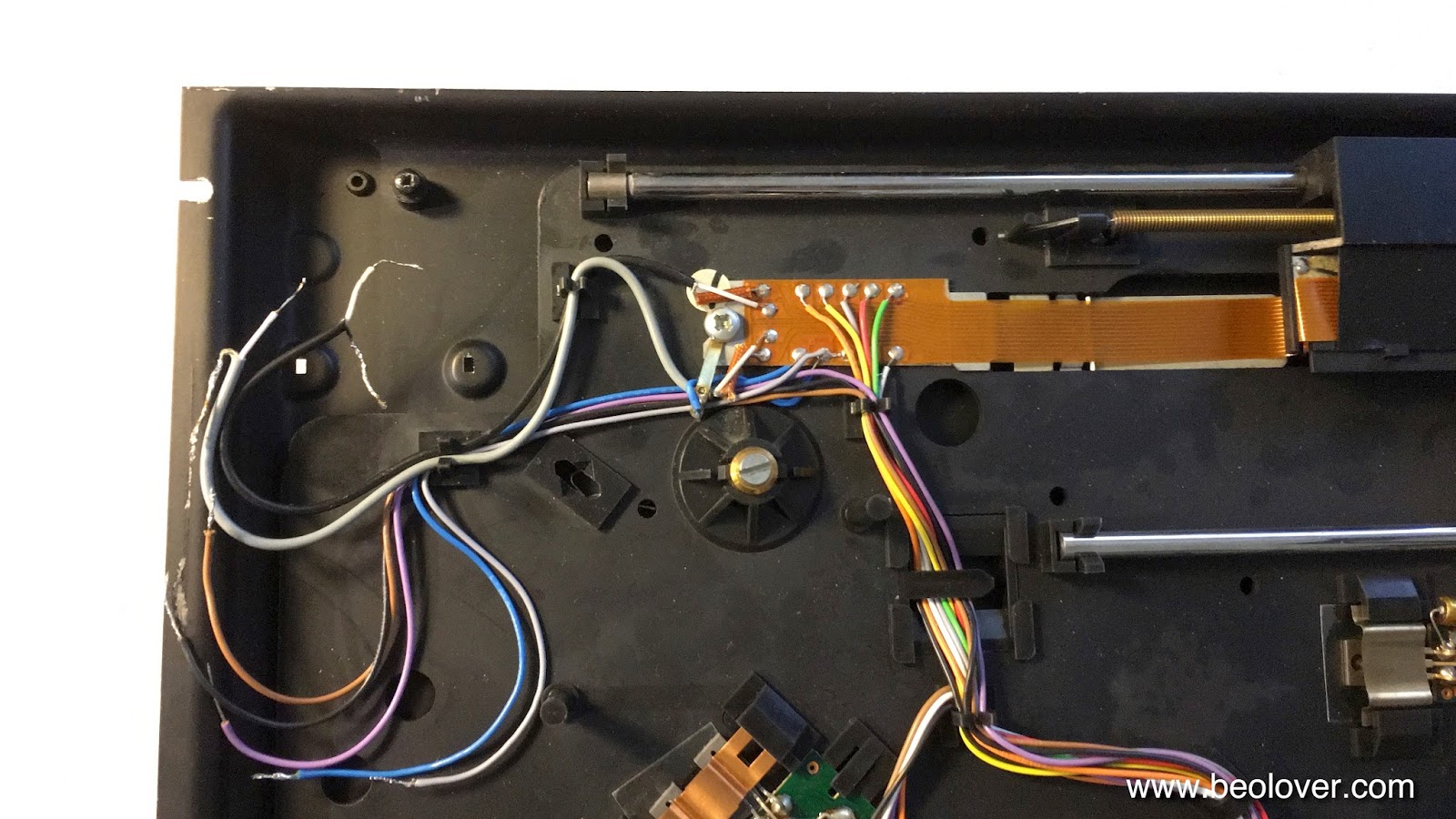
After replacing the light bulb in the sensor arm with an LED assembly it was time to look into the RCA plug 'conversion' of this Beogram 4004 (5526). This shows the output cable in the condition when I received this Beogram:
Not a very inspiring sight. The blue and yellow leads are the Beolink signal lines that allow controlling the 4004 via a Beomaster 2400. We decided to return this 4004 to its original DIN7 output scheme. Originally the 4004 came with a convertible male DIN7 plug, which can be turned into a standard DIN5 by unscrewing the two pins that are extra in the DIN7 format. This shows a plug as seen on a 4004 I restored a few years ago:
The two outer pins were removed so that the plug essentially acted like a standard DIN5 phono output. Unfortunately, such DIN7 plugs are not available anymore. A solution I came up with is to install female DIN7 plug that has all the signals on it. If extended with a DIN7 cable it turns into a DIN7 male output that will properly work with a Beomaster 2400. Extend it with a DIN5 or a DIN5-to-RCA adapter and a standard non-B&O phono output is achieved.
This shows the female DIN7 plug during the installation:
Note that the leads need to be soldered in a mirrored pattern compared to that applied for a male DIN7 plug, since male-male DIN5 and DIN5-RCA jumper cables mirror the leads for symmetry reasons.

This shows the DIN7 connected to a DIN5-to-RCA jumper cable:
The system ground connection is on a separate wire (not visible on this photo) that it can be connected to the GND terminal of the RCA input amplifier.


Friday, June 9, 2017

Beogram 4004 (5526): Replacement of Convertible DIN7 Plug with DIN7 Socket and an RCA Adapter Cable

Any restoration of a Beogram should include the replacement of the DIN connector to ensure a low impedance signal path on the way to the amplifier. In the case of a Beogram 4004, the DIN connector is a convertible male DIN 7 plug, where the two additional pins can be unscrewed from small sockets. These two pins would carry the remote control signals from a Beomaster 2400, which is designed to control the 'start' and 'stop' operations of the Beogram 4004. An early form of Beolink, so to speak. But of course, if one does not connect to a 2400, these pins are not needed, hence the convertibility. This shows the plug with the empty two sockets at the ends of the 5 pin half-circle:
This type of plug is no longer available, and so I resorted to replacing it with a DIN 7 female socket, which then connects to a jumper cable with the desired number of pins or RCA termination. In essence this approach converts the Beogram 4004 output scheme to that found in the later Beogram 800x models, who have a DIN 7 socket mounted in the back of their enclosures. That way one can connect with both DIN 5 and DIN 7 jumper cables to a non-B&O or B&O amplifier.

Even cable mount DIN 7 sockets are difficult to find these days, but Steve at soundsheavenly.com can provide them. Here are a couple impressions: This shows the socket soldered on:
and with its shield in place:
And finally with a DIN 5 to RCA adapter cable:


Thursday, June 8, 2017

Beogram 4004: Replacement of Convertible DIN 7 Plug with a Female Socket and Adapter Cables

While enjoying the Beogram 4004 that I recently restored I was looking for an adequate modern replacement for its convertible DIN 7 plug. This plug is a special design that does not seem to be made anymore. Here is a picture of its business end:
The picture shows the plug in its DIN5 configuration, i.e. it can now connect with any standard DIN5 amplifier input. The two (threaded) orifices above the pins can hold two more pins, which can be bolted in if the Beogram is to be connected to a Beomaster 2400 to take advantage of its remote control, which can be used to start/stop the Beogram. In essence these two additional pins carry the remote control signals for the Beogram. But, of course, since this is a male plug, the pins have to be removable if the Beogram is to be used in a standard DIN 5 setting.

Sadly, these plugs are nowhere to be found these days, and so, if a new plug is desired, another approach needs to be found to preserve the above 'convertibility'. My solution was to replace the plug with a female DIN 7 socket. That way DIN5 (or DIN5-to-RCA) jumper cables can be used for non-B&O set-ups and DIN7 jumpers can be used to connect to B&O setups. In essence, this modification gives the Beogram 4004 the same connectivity design like the later Beogram 800x, which have a panel mount DIN7 socket in their back panel to receive a suitable jumper cable.
It was pretty difficult to find a decent female cable mount DIN7 socket, but finally Steve at soundsheavenly.com saved the day by providing me with a few DIN7 Deltron sockets for cable mounting.

Here are a few impressions: This shows the socket installed. The red and white leads are the signals and the yellow and blue leads carry the remote control.
It is important to note that the signal leads on a female sockets need to be soldered to the other side of the connectors since male and female plugs have mirrored pin assignments to properly maintain the signal chain through the connections. This shows the fully assembled socket:


This is how it looks with a DIN5 jumper cable (also provided by Steve) plugged in:
This Beogram 4004 is finally ready to be shipped back to its owner!


Friday, December 9, 2016

Beogram 8002: Transplantation of Output PCB

Finally I had some time again to work on the Beogram 8002 that I recently started to restore. The last two weeks were an 'interesting experience' after Michael Fremer's video appeared on analogplanet.com featuring my CleanerVinyl ultrasonic vinyl cleaning equipment. 

The next step in this project was to transplant the DIN7 output assembly from a parts-Beogram 8002 that I acquired from a crooked audio repair shop in Chicago. This unit is now coming in handy here since the 8002 was missing its DIN7 output cluster:
I always wonder what drives people to do such things, but here we are on our interesting little self-absorbed planet...;-).

I extracted the assembly from the parts 8002:
I decided to update the relay with a modern encapsulated unit while I had everything on the bench. The original Omron G2V-2 relay can easily be replaced with its modern G5V-2 cousin, which has the same footprint:
And here is a photo of the installed new relay:
and with its shield clamped on:
This shows the restored wiring:
After verifying that the relay worked properly I installed a grounding switch that allows to connect signal and system grounds if there is a hum problem:
On to the two other issues that I was able to identify: The deck does not detect the absence of records and happily lowers the arm onto the platter. It also has a missing digit in the RPM display. One step at a time.


Thursday, November 17, 2016

Beomaster 8000: Repair of a Damaged In DIN7 Phono Jack That Had Lost All Four Panel Mount Tabs

One of the weak spots in Beomaster 8000s are the phono jacks in the input box under the control panel. The plastic of these jacks becomes brittle over the years, and all it takes to break out the plastic tabs that hold the jack above the input box panel is a firm push to get the DIN7 plug from a Beogram into the jack. And then the jack is inside the connector box, and the cable probably not even connected. And this is how this sorry outcome looks like:
Usually, only the top (outside) tabs break off, and there is a fix for this with two 3D printed inserts that replace these tabs. A detailed report on this repair and a video is posted here. This shows the tabs that I installed in this Beomaster:
These tab replacements are available to other enthusiasts via the Beolover Shapeways store. By the way, they also repair the jack on Beocord 8000 and 9000 units. They are also often broken out.

Unfortunately, this Beomaster's DIN7 jack posed a new challenge: It's inside tabs that hold it below the panel (so one can pull the plug without dislodging the jack) were also gone.

Since the original jacks are impossible to find these days, and even replacements from donor units are very hard to come by, I had no other recourse than trying fixing this with yet more 3D printed parts!

But first I needed to repair several disconnected leads, which probably were a casualty of a previous repair attempt. Several jumpers were broken off:
Luckily, while repairing the contact box of another Beomaster 8000 I made an extensive sketch of all the wire connections in this box, and so I was able to restore the connections without trouble:
After this I designed the replacement tab for the right side of the jack. Since it is pretty much impossible to print flexible precision parts on this size scale, I resorted to a two-pronged approach, where I first designed a static tab without spring force that would be glued onto one of the sides of the jack. This would allow to insert the jack diagonally into the cutout together with the outside tab replacements. Then, once seated, the plan was to glue another static tab into the other side of the jack from the inside of the box.

Alright, that was the plan...and here is the execution:

This shows the right side tab:
It fits into the side 'cavity' of the jack that is shown here:
This shows the part seated (with a dab of epoxy underneath):
I clamped it for an hour until I could be sure that the epoxy was fully hardened:
Then I inserted the jack together with the top tabs:
The next step was to design a tab for the other (left) side of the jack that I could get into the 'cavity' from the inside of the connector box:
I made it considerably longer than the other one. This gave me enough 'meat' to handle it on the inside and guide it into the space between jack and panel. I put some double sided tape on the contact surface and then inserted it into the space:
The part fits very snugly, and my hope is that the double sided tape will hold it in place reliably once pressed in. This will allow extracting the jack again if necessary in the future, in case there are further repairs necessary etc...I always thrive to make my repairs and updates 'reversible' in case a better solution comes along in the future.

The tight fit required me to use tongue and groove pliers adjusted to fit the task:
And this is how it looked after the repair was completed:
Almost like new! Beolovely! I gave this assembly a bunch of plug-in and -outs with a tight fitting DIN7 cable, and it seems to hold up nicely. But I will recommend to my customer to hold the jack down while pulling out the plug. Looks like we are getting close to buttoning this baby up and giving her a first spin!