Featured Post

Beolover SyncDrive: DC Platter Motor Replacement for Beogram 4002 and 4004 (Type 551x and 552x)

Late Beogram 4002 and the 4004 (Types 551x and 552x), which have DC platter motors instead of the earlier synchronous AC motors usually suff...

Showing posts with label electrolytic capacitor. Show all posts

Sunday, February 27, 2022

Beomaster 4400 Type 2419: Replacing the Deteriorating Electrolytic Capacitors

As I work my way through the long task of rebuilding the front panel switches of this Beomaster 4400 I was able to take some time to get the old electrolytic capacitors replaced on circuit boards PCB 2, PCB 3, PCB 4 and PCB 5.

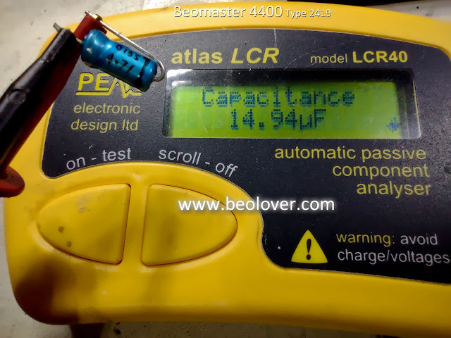
I like to measure all of the capacitors I remove to make a note of how bad the old capacitors have gotten to.  In the case of this Beomaster 4400 almost all of the electrolytic capacitors were way out of tolerance.
Many were fifty percent or more from their rated value.  Most electronic designs like this Beomaster 4400 allow twenty percent on their electrolytic capacitors so this Beomaster was in dire need of the upgrade.

Here are a couple examples of the worst capacitors that I came across and replaced.
A 4.7uF capacitor


A 1.0uF capacitor
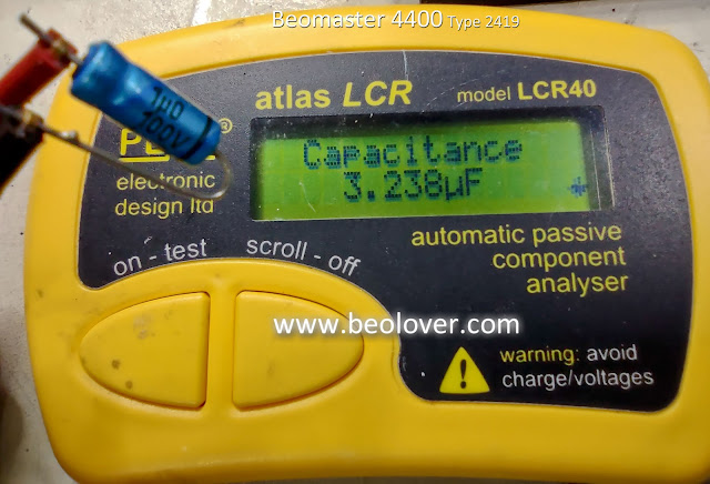


Both of those were three times their rated value!

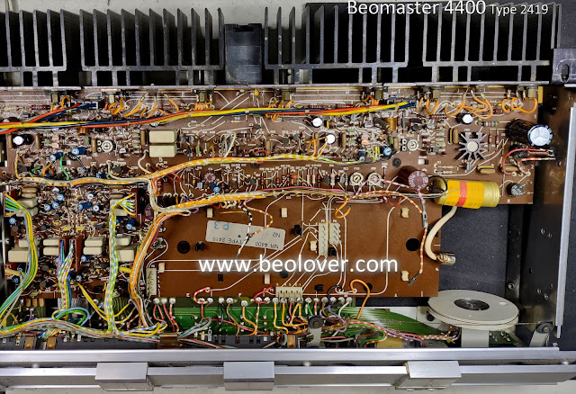
Here are the before and after pictures of the PCB 5 (AF Amplifier, Power Supply, Muting and Silent Tuning) capacitor replacements.

Before


After
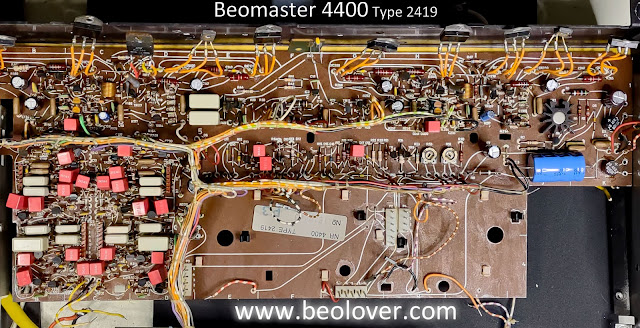


Note that I still haven't installed the new trimmer resistors for the left and right channel no-load current biasing in the output amplifiers. I will do that after the capacitor replacements.


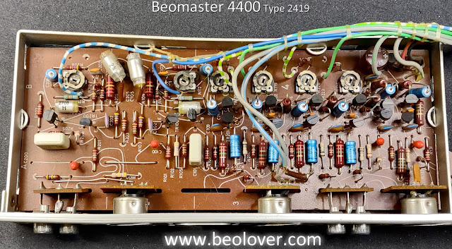
Here are the before and after capacitor replacement photos of PCB 4 (Pre-Amplifier)

Before


After
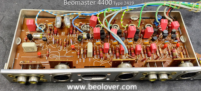


Note that I kept the four tantalum capacitors on the Pre-Amplifier board.  I de-soldered them for testing and all four measured almost right on their rated value so I kept them.  The other, electrolytic capacitors were all way out of tolerance as the ones I replaced on PCB 5.

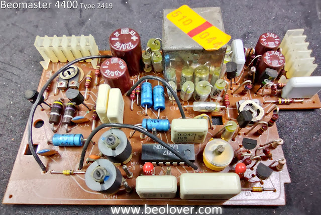
Next is PCB 3 (Stereo Decoder and Indicator Circuit Board).
It also has some tantalum capacitors (two) that I kept because they measure good.

Before


After
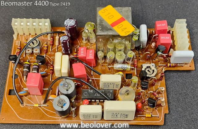


Finally, PCB 2 (IF-Section Circuit Board).  PCB 1 (Front End) has one tantalum 10uF, 10V capacitor inside the metal box. It measured good so it won't be replaced. 

PCB 2 only had two electrolytic capacitors to replace (a 4.7uF and a 1.0uF capacitor).
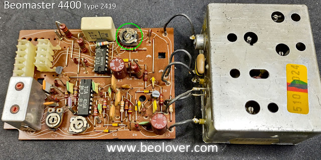
I did discover a bad trimmer resistor and will replace it when I go over the circuit boards again to check the trimmers.

Here are the before and after photos of PCB 2
Before


After


As you can see, trimmer resistor 2R10 has problems and is falling apart.
Now that the capacitor replacement on the circuit boards is complete I will check the condition of the trimmer resistors and replace any that are faulty.

I also still have the two large filter capacitors to replace for the output amplifier rail voltages.

Of course there is still the matter of finishing up the restoration of the control panel switches so I still have quite a bit of work to do on this Beomaster.

Sunday, January 6, 2019

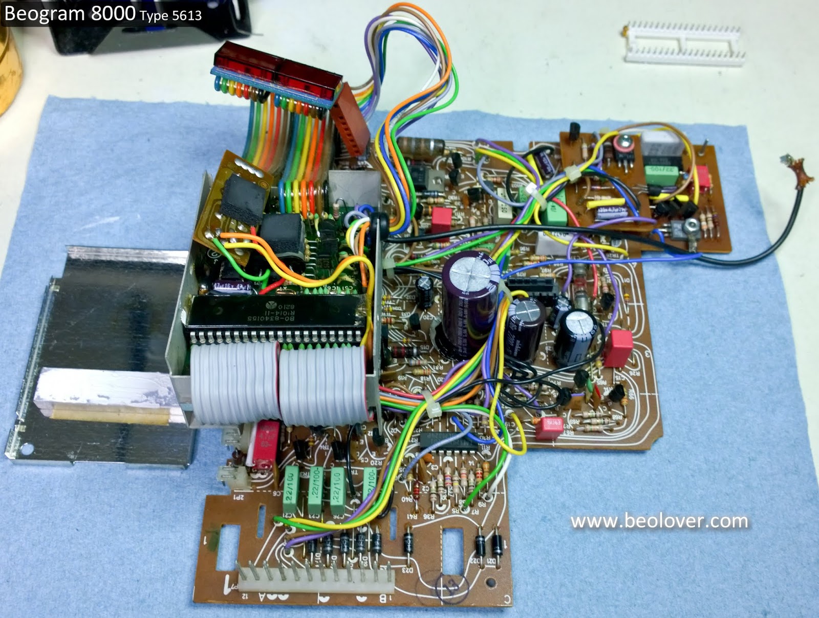
Beogram 8000 Type 5613: Recapping the main board and microcomputer board

The capacitor replacement on the main board and microcomputer board is complete. The microcomputer board also got a new socket for the microcomputer IC and the solder joints were reflowed on all of the board connector pins.

Here is the start of the main board recapping.


A nice small board plus three smaller boards. It should be pretty easy.

That's what I always think but it turns out this board takes me longer than any other Bang & Olufsen board from the period. You have to disassemble the two add on boards and the microcomputer board is difficult because there is so little space to get to the single capacitor on it.

There are two small 1uF capacitors on the trace side of the main board so I will do those first.


One got nicked but is okay.


The main board recapping goes pretty quick until I get to the largest capacitor, C27.


The original C27 is attached securely to the main board by three mounting pins which are connected to the negative side of the capacitor plus the single positive lead...four mounting points. New, replacement electrolytic capacitors don't come with the same mounting options (or at least I haven't found any) and I don't like the way the two lead replacement capacitor is wobbly using just the two mounting points.

My solution is to pop off the original C27 base (with the three prongs) and use it on the new capacitor. I solder the negative lead to the base then put a bead of black hot glue around the edge.


That makes for a good solid fit.


That takes care of the main board (and the two, small add-on boards).
On to the microcomputer board.


The microcomputer board only has one capacitor...C28. Only one but it is difficult.
Its positive lead is soldered to the trace side of the board while the negative lead is soldered to component side of the board. The proximity to the microcomputer IC makes it a little risky so to be safe I don my anti-static strap, ground the metal box containing the microcomputer board and remove the microcomputer IC.


On this particular unit the small add-on board inside the box gets its power from the C28 capacitor directly across the C28 leads. That adds to the removal difficulty.

Since I removed the microcomputer IC for safety I always go ahead and replace the 40-pin IC socket. Removing the socket also gives me more working room. The new replacement socket is a heavier duty socket.


With the microcomputer IC and socket removed I am able to get my soldering iron on C28 to remove it.


For the replacement C28 I will run both its positive lead and the positive power wire (red wire) from the add-on board together to the trace side.  The C28 negative lead also goes through the PCB but does not have a solder point on the trace side.


The add-on board negative power wire (black wire, ground) solders to the C28 negative lead and the ground solder pad on the component side. You can see how having the microcomputer IC and socket make that a much easier task.


Now the new microcomputer socket can be installed.


Here is the completed microcomputer board along with the main board. I won't attach the lid to the microcomputer board box until I make sure the Beogram powers on and works.


Once I verify the recapped boards are good I will be able to start in on the service manual checks.

Monday, October 8, 2018

Canada Beomaster 8000: Final four capacitors replaced

There are just four remaining capacitors to replace on the Beomaster 8000 from Canada. Two capacitors each on the microcomputer board and the display board.

The microcomputer board on this Beomaster is about as pristine as you will find. No need for any board cleaning on this beauty.


The two capacitors to replace on this board are inside the metal shield box. There is a top piece to the shield box (shown above) and a bottom piece shown here.


The inside of the bottom cover has a paper insulator to keep the metal cover from shorting component leads.

Here is the inside of the box (front and rear)


I will say it again...this board is in beautiful condition. The two capacitors to change out are a 1uF and a 22uF capacitor.


I am only doing the two capacitors on this board for now. I want to check the Beomaster 8000 power supply so I will re-install this recapped microcomputer board for that test. Once the power supply test is verified I will come back to this board and change the two oscillators as well as reflow a number of solder joints.


I will do a similar thing with this Beomaster's display board.  For now I will just change out two capacitors on that board but will return to it later for the restoration of the segmented displays, replacing the four incandescent lamps and reflowing solder joints.

Here is the display board as I received it.


The two capacitors are easy to get to so I quickly changed them out.


Here is the completed board.


Thursday, September 27, 2018

Canada Beomaster 8000: Preamplifier Board

The Beomaster 8000 preamplifier board is the next board I restored.  The tasks are similar to the Filter & Tone Control board.  The electrolytic capacitors will be replaced, the LF353N opamps will be updated with new ones.  Board connector solder joints will be reflowed.  The board is cleaned and the input source level trimmers are cleaned.

Here is the preamplifier board prior to restoration.


This is the board where the components to be replaced have been removed. I will clean the board with alcohol and the trimmers cleaned with Deoxit.


This is the board with new capacitors and opamp sockets.


Finally, the completed board.


Thursday, July 12, 2018

Beomaster 4400 (2419): Into the Recap

These seventies era Beomaster receivers have a low profile and are quite a challenge to open up into a service position. I like the way the eighties era Beomaster units were designed with some consideration for the service technicians. Oh well, it is what it is. The Beomaster 4400 is an improvement over the Beomaster 4000. There are some board connectors.

Here is the Beomaster opened up and ready for recapping.


The PC5 board has the most recapping work and does not unplug completely for removal. I disconnected enough wires to it so I can get to where I need to with regards to replacing capacitors but I will tackle the PC5 board after I recap the smaller boards.

I started with the PC3 - Stereo Decoder and Indicator Circuit board. It is a good one to warm up on.


Here is the recapped board. For now I am leaving the trimmer resistors as they are on the FM boards. I will replace them as necessary during the Beomaster performance testing. 


Next are the PC1 and PC2 FM boards. There are just three capacitors to replace between them.


...and here are those boards after the recap.


Now for the PC4 - Preamplifier board.


On this board I also changed out the six 50KΩ trimmer resistors as I recapped the board.


Tomorrow I will tackle the large, PC5 board and the two reservoir capacitors.