While starting on the two Beomaster 8000 restorations the Beomaster 4400 has been playing away in my office for several days without a hiccup. A final series of listening tests are in store for this Beomaster before I pack it up and send it home.
The owner of this Beomaster 4400 receiver has a pair of Beovox M100.2 and Beovox MC120.2 speakers. It so happens that I do as well. So while he may not hook things up like this we felt a nice final test on this restoration would be to spend a couple of days with this Beomaster driving my two pairs of speakers.
But first....
I have been test playing the Beomaster 4400 in my office with the top cover still off. That was so I could monitor the inside as I played it. I wanted to know immediately if the problem with the two main board resistors returned. That was three weeks ago. No such problem since and I have been using the heck out this receiver.
Now to the Beomaster cabinet. It turns out it had a very weak rear trim panel and it finally broke. That called for a cosmetic repair. I also noticed that the bottom metal cabinet plate had bad rust areas around the cabinet feet.
First the cabinet.
Here is the damaged cabinet piece dry fitted back in place.
For this type of repair I use a slow drying wood glue and clamp the broken piece tightly into place. That will cause excess glue to ooze out the break seam. While it is wet I wipe all of the excess completely off. Then I rub in rosewood sanding dust that I collect from some pieces of rosewood veneer I keep handy for these type of situations. The rosewood sanding dust particles darken the light color of the break seam.
There is still a scar but when the cabinet is resanded and treated with fresh oil (boiled linseed oil) it looks quite acceptable in my opinion. It also helps that the break is at the back of the cabinet and on the side.
We thought about substituting a spare Beomaster 4400 cabinet but this is a really pretty cabinet.
Another cabinet fix I tended to was the left front edge. The inner particle board had started to wear away. It wasn't visible but I felt the amount of material was kind of thin and needed reinforcement. I made a little mold and used some JB Weld gray epoxy to build the area up again. It turned out quite nicely.
The last bit of cabinet repair business was the bottom panel rust.
Here is one side of the cabinet base. The screws that attach the feet to the base are rusted and areas all around the rubber feet have rust corrosion.
I was surprised the screws came out without any of them breaking.
Interestingly the bottom panel was the only place this cabinet had any rust.
My fix for this type of problem is to sand down the rust damage until all of the reddish brown rust is gone. Then I wipe away the dust and start applying a rust neutralizer. I do three coats of neutralizer wiping away each coat about fifteen minutes apart. I leave the third coat on for twenty-four hours. Then I lightly sand it again.
Now it is ready for some satin black Rustoleum spray paint and new feet.
Speaking of the feet here are the original rubber feet next to the four new feet I am going to install. The feet are about 16mm in diameter and 6mm high.
The new feet have a nice metal sleeve to keep the mounting screw from digging into the rubber.
Here is the bottom panel re-painted and re-installed with new rubber feet and new screws.
There is some visible scarring from the rust corrosion but this is the bottom of the cabinet and the corrosive elements have been neutralized. I feel good about the fix. I could not stand leaving the old feet in place especially with that corrosion going on.
I moved the re-assembled Beomaster to a spare room where I often do some additional listening tests.
That is one reason you can see a lot of wires under the MC40 B&O cabinet.
Speaker placement is (almost) everything when listening to music. I figured I would experiment with various speaker positions during this Beomaster 4400 test but sometimes it just sounds perfect the first time.
This was one of those cases. The combination of the M100.2 speakers on the inside and the MC120.2 speakers just a little forward and to the side work amazing in this room. I listened to music for about an hour so far (at around 60dB from 10 feet away). The dynamics of the music are really good. The next few days should be a lot of fun.
Featured Post
Beolover SyncDrive: DC Platter Motor Replacement for Beogram 4002 and 4004 (Type 551x and 552x)
Late Beogram 4002 and the 4004 (Types 551x and 552x), which have DC platter motors instead of the earlier synchronous AC motors usually suff...
Showing posts with label 2018JG07BM4400. Show all posts
Wednesday, August 22, 2018
Monday, August 6, 2018
Beomaster 4400 (2419): 30 Hour 60dB Test
Functional testing update...
Because of the earlier incident with the left channel 5R173 and 5R174 resistor failures I am putting this Beomaster through extra long burn-in testing.
Over the weekend this receiver successfully played continuously for thirty hours at a volume level that produced 60dB to 65dB of sound out of my Beovox S55 speakers (measured from 15 feet away).
The output transistors on the heat sinks measured around 100°F to 120°F at various times during the thirty hour test.
The testing continues.
Because of the earlier incident with the left channel 5R173 and 5R174 resistor failures I am putting this Beomaster through extra long burn-in testing.
Over the weekend this receiver successfully played continuously for thirty hours at a volume level that produced 60dB to 65dB of sound out of my Beovox S55 speakers (measured from 15 feet away).
The output transistors on the heat sinks measured around 100°F to 120°F at various times during the thirty hour test.
The testing continues.
Friday, August 3, 2018
Beomaster 4400 (2419): Preparing for Functional Tests
The Beomaster 4400 has been powering on and off without any problems since the 5R173 and 5R174 incident from the last post. I am satisfied it is ready to move on to functional testing and the long burn-in tests.
I re-assembled the bottom part of the cabinet and re-attached the slider control bar. While it was removed I cleaned off the old grease and applied new, clean grease for the slide controls.
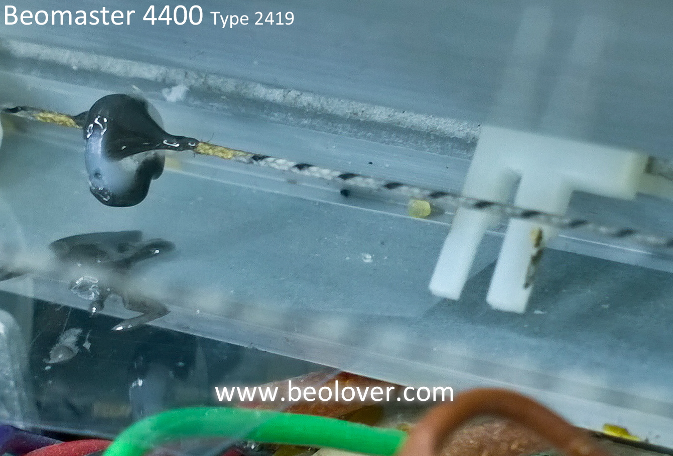
In lining up the slider control slots with their catches I saw that the tuning cord catch for the tuning dial had started to fall apart. The main plastic post was mostly missing. It looked like the catch was mostly hardened glue.
That left over clump of glue wasn't going to fly. In fact more pieces of it started to crumble when I touched it. I needed to fashion a substitute.
After looking through my parts bins and thinking about it I decided a nylon, M2 washer could become the new tuning cord catch. I cut a small section out of the washer so it would fit over the tuning cord. I marked either side of the old, remaining catch then carefully removed the old piece.
I used Araldite fast setting epoxy to attach the washer to the tuning cord.
After test fitting that with the tuning dial slot I added some JB Weld fast setting epoxy in the washer slot that I had cut and along the top of the tuning cord and the washer. That secures the washer better and provides a little mounting edge to fit in the tuning dial slot. One reason to use JB Weld for that last part shaping was because the color difference helped be tell the glue was where I wanted it.
I let the epoxy cure then tried out the new catch. It fits great and looks like it will work well.
Before I put the top cover on I will do some functional testing with the reassembly I have done so far. Now for a little relaxation and test listening of the Beomaster.
I re-assembled the bottom part of the cabinet and re-attached the slider control bar. While it was removed I cleaned off the old grease and applied new, clean grease for the slide controls.
In lining up the slider control slots with their catches I saw that the tuning cord catch for the tuning dial had started to fall apart. The main plastic post was mostly missing. It looked like the catch was mostly hardened glue.
That left over clump of glue wasn't going to fly. In fact more pieces of it started to crumble when I touched it. I needed to fashion a substitute.
After looking through my parts bins and thinking about it I decided a nylon, M2 washer could become the new tuning cord catch. I cut a small section out of the washer so it would fit over the tuning cord. I marked either side of the old, remaining catch then carefully removed the old piece.
I used Araldite fast setting epoxy to attach the washer to the tuning cord.
After test fitting that with the tuning dial slot I added some JB Weld fast setting epoxy in the washer slot that I had cut and along the top of the tuning cord and the washer. That secures the washer better and provides a little mounting edge to fit in the tuning dial slot. One reason to use JB Weld for that last part shaping was because the color difference helped be tell the glue was where I wanted it.
I let the epoxy cure then tried out the new catch. It fits great and looks like it will work well.
Before I put the top cover on I will do some functional testing with the reassembly I have done so far. Now for a little relaxation and test listening of the Beomaster.
Wednesday, August 1, 2018
Beomaster 4400 (2419): Amplifier Frequency Response Check Plus A Fault Detour
In the last post I showed the results of some THD tests with the Beomaster 4400. I used a 1KHz, 2Vp-p sine wave input signal at Tape 1 and Tape 2. Then I used the QuantAsylum QA400 analyzer to measure and display the output signal across 8Ω dummy speaker loads. I also ran the volume of the Beomaster up to its maximum output right before the overload lamp illuminates. The Beomaster passed those performance tests really well.
After letting the Beomaster sit for a couple of days while I took care of some other things I powered it back up for some frequency response testing. To my horror and surprise the left channel output amplifier had smoke! I quickly unplugged the Beomaster and examined the damage. The smoke came from the main board 5R173 and 5R174 resistors. They are 68Ω 1/8W metal film resistors and completely failed where they were open circuit now. Surprisingly there was not burnt areas of the circuit board and no other components appeared to be damaged. Quite puzzling considering the Beomaster had just come off almost 30 hours of testing. Twenty-four hours of that was continuous playing of music on the Beovox S-55 speakers.
The next step was to try and figure out if there were other damaged components and how many.
Here is the related circuit. It is the left channel output amplifier circuit and shows that the two 68Ω resistors connect to the -35VDC rail. They get current when 5TR119 turns on. Too much current had to of gone through both R173 and R174 to cause them to burn up.
Here are the two burned resistors.
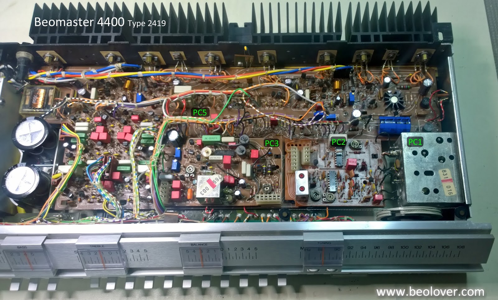
Here is the PC5 board - fault area. The photo shows the D103 12V zener removed for testing.
I removed related components to R173 and R174 as well as some other components that were in close proximity to test if anything else was damaged.
The D103 12V zener diode was a suspect because it controls TR119 which must of allowed too much current down through the two 68Ω, 1/8W resistors.
D103 was placed on a breadboard with a 1KΩ resistor to check if the zener still works. Using a bench power supply I applied 30VDC across D103 and the load resistor. The zener held at around 12.5VDC. I tried this several times and D103 appeared to be fine.
I couldn't find any components that tested faulty so I re-installed everything I removed.
Next I used my variac to slowly apply AC power to the Beomaster while watching R173 and R174. I reached 120VAC on the variac without incident.
At this point I have to figure there was some problem on the board. Most likely a bad solder joint. Uninstalling and reinstalling the components around the fault area forced a re-flow of the solder joints.
I powered the Beomaster off and on several times and it appeared to be back to normal.
A little history on this Beomaster unit...
The owner told me when I started on the restoration that he had smelled burning in the receiver before but that it went away. After a period of time though, there was a loud squawk in one of the channels and the Beomaster stopped functioning. The Beomaster was taken out of service and eventually sent to me.
When I opened the Beomaster for restoration one of the inspections I did was to look for burnt components. I didn't find any. I thought the recapping work took care of any bad component behavior and solder joint problems. Then this fault occurred...even after the lengthy initial burn-in testing.
So I still worry there might be a weak component that is really the culprit. That means I will have to put this Beomaster through a much longer burn-in test period once I wrap up the frequency response and functional tests.
Continuing on with the frequency response measurements....
Like the 1KHz THD tests I used the Beomaster tape inputs to apply the QA400 frequency response impulse stimulus. The QA400 inputs were connected to the 8Ω dummy speaker loads through a QA190 differential voltage probe. The frequency response measurement function of the QA400 was then used to measure the response curve.
My initial frequency response measurements were okay, not great. Even with the differential probe measuring one channel at a time I get some noise that makes taking the measurements I would like a little difficult.
Here are the first set of frequency response curves I measured.
Both channels roll off a little steeper than I would like and the right channel is not flat at all.
The Beomaster 4400 Linear switch allows you to bypass the tone control circuit so I tried the measurements with the switch engaged.
That is a definite improvement versus going through the tone control circuit.
I cleaned the bass, treble and balance slider pots as well as the high and low filter switches to see if that helped the tone control path.
It looks like the right channel improved with a flat curve between 100Hz and 3KHz now. My probe isn't doing a good job below 100Hz however so I am not able to get an accurate assessment of that part of the response.
Soundwise this Beomaster sounds good to me so I will keep these measurements filed as a reference for the next Beomaster 4400 units I have in my backlog.
The next steps for this Beomaster are to check out the phono input and the tape record paths of Tape 1 and Tape 2. Once those have been tested I will hook this Beomaster to some audio components in a listening room for an extended burn-in test. If the R173 and R174 over current problem is still there it should expose itself during that period.
After letting the Beomaster sit for a couple of days while I took care of some other things I powered it back up for some frequency response testing. To my horror and surprise the left channel output amplifier had smoke! I quickly unplugged the Beomaster and examined the damage. The smoke came from the main board 5R173 and 5R174 resistors. They are 68Ω 1/8W metal film resistors and completely failed where they were open circuit now. Surprisingly there was not burnt areas of the circuit board and no other components appeared to be damaged. Quite puzzling considering the Beomaster had just come off almost 30 hours of testing. Twenty-four hours of that was continuous playing of music on the Beovox S-55 speakers.
The next step was to try and figure out if there were other damaged components and how many.
Here is the related circuit. It is the left channel output amplifier circuit and shows that the two 68Ω resistors connect to the -35VDC rail. They get current when 5TR119 turns on. Too much current had to of gone through both R173 and R174 to cause them to burn up.
Here are the two burned resistors.
Here is the PC5 board - fault area. The photo shows the D103 12V zener removed for testing.
I removed related components to R173 and R174 as well as some other components that were in close proximity to test if anything else was damaged.
The D103 12V zener diode was a suspect because it controls TR119 which must of allowed too much current down through the two 68Ω, 1/8W resistors.
D103 was placed on a breadboard with a 1KΩ resistor to check if the zener still works. Using a bench power supply I applied 30VDC across D103 and the load resistor. The zener held at around 12.5VDC. I tried this several times and D103 appeared to be fine.
I couldn't find any components that tested faulty so I re-installed everything I removed.
Next I used my variac to slowly apply AC power to the Beomaster while watching R173 and R174. I reached 120VAC on the variac without incident.
At this point I have to figure there was some problem on the board. Most likely a bad solder joint. Uninstalling and reinstalling the components around the fault area forced a re-flow of the solder joints.
I powered the Beomaster off and on several times and it appeared to be back to normal.
A little history on this Beomaster unit...
The owner told me when I started on the restoration that he had smelled burning in the receiver before but that it went away. After a period of time though, there was a loud squawk in one of the channels and the Beomaster stopped functioning. The Beomaster was taken out of service and eventually sent to me.
When I opened the Beomaster for restoration one of the inspections I did was to look for burnt components. I didn't find any. I thought the recapping work took care of any bad component behavior and solder joint problems. Then this fault occurred...even after the lengthy initial burn-in testing.
So I still worry there might be a weak component that is really the culprit. That means I will have to put this Beomaster through a much longer burn-in test period once I wrap up the frequency response and functional tests.
Continuing on with the frequency response measurements....
Like the 1KHz THD tests I used the Beomaster tape inputs to apply the QA400 frequency response impulse stimulus. The QA400 inputs were connected to the 8Ω dummy speaker loads through a QA190 differential voltage probe. The frequency response measurement function of the QA400 was then used to measure the response curve.
My initial frequency response measurements were okay, not great. Even with the differential probe measuring one channel at a time I get some noise that makes taking the measurements I would like a little difficult.
Here are the first set of frequency response curves I measured.
Both channels roll off a little steeper than I would like and the right channel is not flat at all.
The Beomaster 4400 Linear switch allows you to bypass the tone control circuit so I tried the measurements with the switch engaged.
That is a definite improvement versus going through the tone control circuit.
I cleaned the bass, treble and balance slider pots as well as the high and low filter switches to see if that helped the tone control path.
It looks like the right channel improved with a flat curve between 100Hz and 3KHz now. My probe isn't doing a good job below 100Hz however so I am not able to get an accurate assessment of that part of the response.
Soundwise this Beomaster sounds good to me so I will keep these measurements filed as a reference for the next Beomaster 4400 units I have in my backlog.
The next steps for this Beomaster are to check out the phono input and the tape record paths of Tape 1 and Tape 2. Once those have been tested I will hook this Beomaster to some audio components in a listening room for an extended burn-in test. If the R173 and R174 over current problem is still there it should expose itself during that period.
Tuesday, July 24, 2018
Beomaster 4400 (2419): Amplifier 50W Output Check
As a burn-in test I left the Beomaster playing the FM tuner for 24 hours. I varied the volume level every now and then but always kept it at normal listening levels (soft to loud). The output transistor heat sinks remained cool to the touch all during the burn-in testing and of course the sound was good.
Now it is time to see how the Beomaster does when full output power is requested.
First the test setup. My source input voltage is a 1KHz sine wave at 2Vp-p into the Beomaster 4400 Tape 2 DIN plug.
The output of the Beomaster will be measured using the speaker 2 output connected to my 8Ω dummy speaker loads. These are power resistors with heat sinks mounting on an even larger heat sink as the resistor loads will get pretty hot when full power is applied.
Here is the Beomaster with speaker 2 selected, Tape 2 selected and the volume level set to output 50W (the rated power output into 8Ω as listed in the Beomaster 4400 manual). I used my DMM to monitor the speaker load to check when 50W was reached. The QA400 analyzer connects to the dummy load as well via a differential probe.
The power test worked nicely. I ran the volume up until I got to 20 V on the DMM. A little bit higher and the Beomaster overload lamp came on as I would expect. I backed the volume down a bit to measure the distortion of the 1KHz signal across the dummy loads.
Both channels measured quite good. Just below 0.02% THD for a 1KHz signal at maximum power.
As with previous amplifier measurements using this setup... I can't really do a direct comparison with the B&O published specifications as their test equipment and methods are different from mine. The best I can do is repeat my own test setup with the amplifiers I restore and collect that data for my reference. In comparison to my recent Beomaster 8000 output tests the THD on this Beomaster 4400 also measures very good. Well below what human ears can hear.
Sunday, July 22, 2018
Beomaster 4400 (2419): No Load Current Adjustment
Here is a quick updated on the Beomaster 4400. Yesterday the Beomaster was powered up for the first time after the restoration. All of the power supply voltages checked out good. Continuing on today I set the no load current. That procedure calls for measuring across the two emitter resistors on each channel with the volume at zero and no speakers connected. The idle current trimmers are adjusted so that each channel is at 10mV to 15mV across their respective output emitters.
To start with I am setting these on the low end of the range so I set each to 10.2mV. I will test with that for a while and monitor the temperatures of the output transistors. Once I am comfortable with that I will look at increasing the output.
Here are the left and right channel adjustments.
I'm afraid I couldn't wait to hear what this amplifier sounds like so I connected up an iPod Nano to TP2 and the Beomaster speaker 1 outputs to my Beovox S-55 speakers (that I always test with in the shop).
I realize it is too early and there are still performance tests to run but the Beomaster sounds great in this first test.
I checked out the FM tuner controls. The large tuning dial and the six presets all work. Stereo decoding appears to be working fine. The signal strength looks strong but I will check everything out further in the next few days.
So far I have had power on the Beomaster for over an hour with it playing through the Beovox S-55 speakers. The heatsink fins remain cool. I will let the Beomaster continue to play for twenty-four hours.
To start with I am setting these on the low end of the range so I set each to 10.2mV. I will test with that for a while and monitor the temperatures of the output transistors. Once I am comfortable with that I will look at increasing the output.
Here are the left and right channel adjustments.
I'm afraid I couldn't wait to hear what this amplifier sounds like so I connected up an iPod Nano to TP2 and the Beomaster speaker 1 outputs to my Beovox S-55 speakers (that I always test with in the shop).
I realize it is too early and there are still performance tests to run but the Beomaster sounds great in this first test.
So far I have had power on the Beomaster for over an hour with it playing through the Beovox S-55 speakers. The heatsink fins remain cool. I will let the Beomaster continue to play for twenty-four hours.
Beomaster 4400 (2419): Reassembly and Power Checks
Today I reassembled the electrical components of the Beomaster 4400 and performed the all important first power on test. The goal here was to verify all of the board component work is correct and the Beomaster can be plugged in, turned on and all of the power supply voltages are good.
I installed the FM boards (PC1, PC2 and PC3) first.
I had removed the shield cover to the main power switch so I reinstalled those parts now.
The last board to install is the PC4 preamplifier board.
As I was tightening the mounting screws of the preamplifier board to the cabinet I was reminded of a problem (in my opinion) with the design of the connector panel. The RCA jacks are too close together. This is also the case on the Beomaster 4000 receiver. I don't own any audio cables with RCA plugs that can mate with the Beomaster 4000 and 4400 receivers. The only solution will be to make my own and use heat shrink tubing instead of the outer shell that comes with the RCA plugs.
You can see that only the bare RCA plugs can fit the space allotted by the Beomaster connector panel.
I always connect Bang & Olufsen source components to the Beomasters so it isn't a problem for me but it is something to be aware of if you are planning on using your Beomaster 4400 for some non-B&O audio source components. The solution in that case is to get an adapter cable that goes from the RCA plugs to a 5-pin DIN plug.
Anyway, just a pet peeve on my part. Continuing on it is time to see what happens when power is applied to this newly recapped Beomaster 4400. In the case of the older Beomaster amplifiers I like to use a variac with a dim-bulb tester on the first power up. It is just added protection in case I missed something.
The Beomaster 4400 powered up fine. That is great so now I checked all of the DC voltages in the Beomaster.
Here is the +15 VDC power check where the regulator 0IC1 attaches to the PC5 board.
Next is the +35 VDC rail voltage at TP3 of PC5.
Then the -35 VDC rail voltage at 5R16 of the PC5 board.
I checked the +24 VDC voltages at the emitters of 5TR3 and 5TR4. Here is a picture of the 5TR3 emitter. Both measured +24 VDC as they should.
Last I checked the -12 VDC at TP15 of PC5.
Very nice. Everything looks good so far. Tomorrow I will start adjusting the no-load current (idle current) and the source levels. Once that is done I will be able to see how this amplifier performs with audio signals.
Subscribe to:
Posts (Atom)