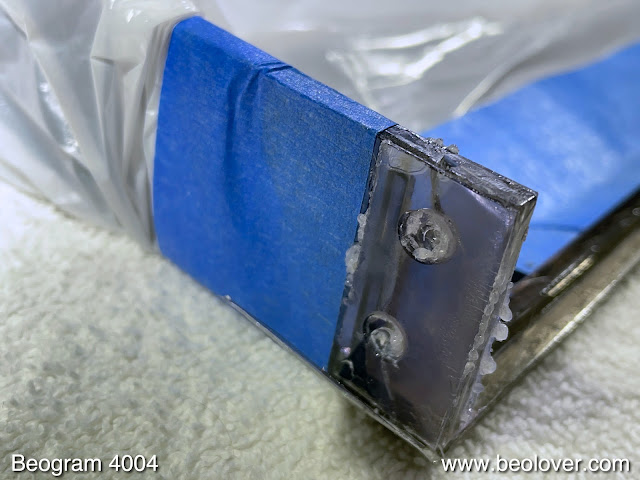
After I repaired the hood of the Beogram 4004 (5526) from Florida, its owner decided to let me do a partial restoration. The unit had shown some platter RPM inconsistencies in the past, indicating that the DC platter motor bearings started to run dry of their oil reserves. This shows the unit with the aluminum panels and platter taken off:

As usual, the first step was to extract the DC platter motor

and disassemble it to get the bearings out for oil infusion:

The bearings are the two small donuts on the black pad upfront. I immersed them in motor oil and pulled a vacuum. Immediately, strong bubbling started:

These bubbles are the air drawn from the porous Oilite bearing material. This makes room for oil to inter diffuse into the bearing. This process usually takes 2-3 days, and so I put the motor aside and focused on the other restoration tasks.
Like most Beogram 4004s, this unit also had degraded transport lock bushings:

While one can ignore their degradation as long as the deck is not moved, the fragments can cause the floating chassis to get stuck if they make it underneath during the rigors of transport. So it is essential to remove all the little bits and pieces when the bushings are finally replaced:

For this it is best to remove the 'guts' of the unit and then put a vacuum cleaner to it:

After removal of all the debris and dust it was time to install the 3D printed replacements. They come in sets of two, where each bushing is replaced with interlocking top and bottom parts for easy installation:

This shows the bottom part in place

and the top part added:

Then the lock mechanism can be reassembled:

After the transport locks were done I replaced the reservoir capacitor of the unit. These big 'cans' often start leaking and then they lose their capacitance causing operational issues due to an unstable power rail. This shows the original capacitor:

And the modern replacement:

Since the unit has a keypad that is still in pretty good condition, my customer decided to get the Beolover Commander remote control module installed:

The Commander allows controlling the deck entirely without touching the precious keypad via a paired Apple remote control. Which is a great idea since the coating that is on the keypads degrades over time due to the acids and fats from the skin when touching the pads. Read more about the Commander here.
The next step was to replace the cracked plastic pulley of the carriage spindle with a precision machined aluminum replica (send me an email if you need one, too. I'll be happy to get you in touch with the B&O aficionado who took it upon himself to create these beauties)

Then it was time for all the adjustments. First I aligned the arms with the platter and then the platter with the aluminum panels that surround it. Once that was all up to spec, it was time to calibrate the tracking weight. I usually install a M3 nut on the screw that is used to adjust the counter weight. This makes the calibration much more stable over time and it can easily survive transport that way. This shows the original circlip that holds the screw in place:

And here after replacing it with a square M3 nut and a washer:

I use a digital gauge to calibrate the spring based tracking force mechanism scale to be accurate around the usually used 1.2g for B&O cartridges:

Another important adjustment is the arm lowering limit:

Basically the needle needs to be able to go beyond the record surface when the arm is lowered, but not far enough to hit the black ribs on the platter. This is a safeguard against electronics malfunctions that may cause the arm to be lowered without a record on the platter (when everything is in order, the Beogram recognizes the absence of a record and the arm lowering mechanism is disabled).
Then it was time to adjust the tracking feedback sensitivity to make sure the arms remain about parallel when a record is tracked:

After I was done with the above tasks, I had a look at the bearings and the bubbling had stopped. This indicates that the infusion process is complete. So I broke the vacuum and extracted the bearings:

I reassembled the motor and installed it for a 24 hrs RPM stability test with the BeoloverRPM device. The BeoloverRPM allows logging the RPM in 10s intervals over extended periods of time. Perfect for the detection of intermittent RPM issues. Another great function of this little device is that one can adjust the RPM precisely:

This is the curve that I measured:

This is pretty good as far as Beogram DC platter motors go. The slight choppiness of the curve is observed with some of these motors after restoration. It usually goes away after playing the deck for a while as the bearing surface is polished by the rotating shaft due to the torque exerted by the drive belt. At any rate these small fluctuations are far smaller than what the human ear can detect. So it was time to clean the aluminum panels and put the deck back together for a test drive.
I selected a vintage vinyl that I recently bought, "Softly...but with that feeling" by Herb Ellis. This near-new condition Japanese pressing was of course cleaned ultrasonically with a CleanerVinyl ProXL setup before listening.
Here is a picture of this beautiful Beogram together with this lovely record:

A perfect combination. The deck performed admirably during this test spin. I will now play it a bit more and then, if nothing else comes up, it is time for it to be picked up by its owner!