Featured Post

Beolover SyncDrive: DC Platter Motor Replacement for Beogram 4002 and 4004 (Type 551x and 552x)

Late Beogram 4002 and the 4004 (Types 551x and 552x), which have DC platter motors instead of the earlier synchronous AC motors usually suff...

Thursday, March 3, 2022

Beogram 4002 (5513): A New Arrival From West Virginia

I recently received a Beogram 4002 (5513) from West Virginia for a full restoration. The unit arrived in good condition in a Beolover-provided shipping container. I extracted it and had a first look:

The unit is in pretty good shape. There are no major blemishes on the hood and it seems the hinges are not cracked. I removed the hood:

The aluminum surfaces are also in decent shape. The keypad shows some light traces of wear. This will be stopped by installing the Beolover Commander remote control module, which allows controlling all functions of a Beogram without touching the keypad ever again.
The plinth is also pretty good. The front corners, which are often damaged are almost pristine:
Like most later 4002 and 4004s this unit has degraded transport lock bushings as is evident from fragments like this
that are distributed around the enclosure. I removed the aluminum panels and the back of the enclosure and had a look under the hood:
I immediately noticed the platter motor was installed in the wrong orientation. My customer had sent me the DC platter motor about a year ago and I was able to restore it, but I guess I failed giving precise enough instructions to re-install it...;-). 
I plugged the unit in and pressed Start. The carriage started moving, found the LP setdown point and the solenoid activated. These are all good signs!
So, in conclusion, I think this may be a straight forward restoration project.


Sunday, February 27, 2022

Beomaster 4400 Type 2419: Replacing the Deteriorating Electrolytic Capacitors

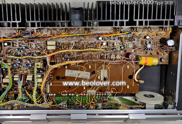
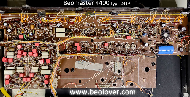
As I work my way through the long task of rebuilding the front panel switches of this Beomaster 4400 I was able to take some time to get the old electrolytic capacitors replaced on circuit boards PCB 2, PCB 3, PCB 4 and PCB 5.

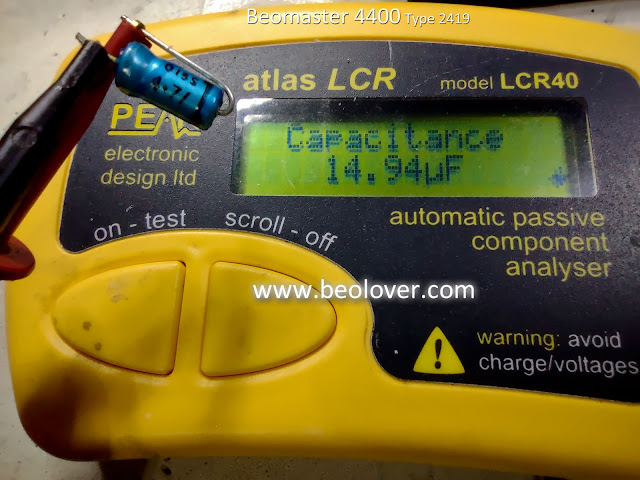
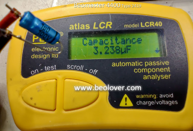
I like to measure all of the capacitors I remove to make a note of how bad the old capacitors have gotten to.  In the case of this Beomaster 4400 almost all of the electrolytic capacitors were way out of tolerance.
Many were fifty percent or more from their rated value.  Most electronic designs like this Beomaster 4400 allow twenty percent on their electrolytic capacitors so this Beomaster was in dire need of the upgrade.

Here are a couple examples of the worst capacitors that I came across and replaced.
A 4.7uF capacitor


A 1.0uF capacitor


Both of those were three times their rated value!

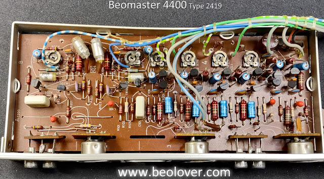
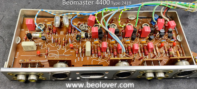
Here are the before and after pictures of the PCB 5 (AF Amplifier, Power Supply, Muting and Silent Tuning) capacitor replacements.

Before


After


Note that I still haven't installed the new trimmer resistors for the left and right channel no-load current biasing in the output amplifiers. I will do that after the capacitor replacements.


Here are the before and after capacitor replacement photos of PCB 4 (Pre-Amplifier)

Before


After


Note that I kept the four tantalum capacitors on the Pre-Amplifier board.  I de-soldered them for testing and all four measured almost right on their rated value so I kept them.  The other, electrolytic capacitors were all way out of tolerance as the ones I replaced on PCB 5.

Next is PCB 3 (Stereo Decoder and Indicator Circuit Board).
It also has some tantalum capacitors (two) that I kept because they measure good.

Before


After


Finally, PCB 2 (IF-Section Circuit Board).  PCB 1 (Front End) has one tantalum 10uF, 10V capacitor inside the metal box. It measured good so it won't be replaced. 

PCB 2 only had two electrolytic capacitors to replace (a 4.7uF and a 1.0uF capacitor).
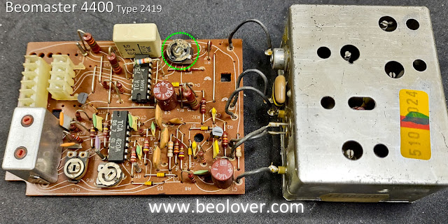
I did discover a bad trimmer resistor and will replace it when I go over the circuit boards again to check the trimmers.

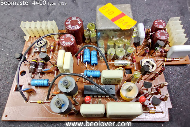
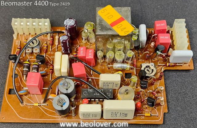
Here are the before and after photos of PCB 2

Before


After


As you can see, trimmer resistor 2R10 has problems and is falling apart.
Now that the capacitor replacement on the circuit boards is complete I will check the condition of the trimmer resistors and replace any that are faulty.

I also still have the two large filter capacitors to replace for the output amplifier rail voltages.

Of course there is still the matter of finishing up the restoration of the control panel switches so I still have quite a bit of work to do on this Beomaster.

Saturday, February 26, 2022

Beogram 4000 AC Platter Motor Restoration

I recently received the AC platter motor of a Beogram 4000 in Massachusetts. The motor exhibited 'knocking' noises, which could not be alleviated by adjusting the motor voltage or tilt. My usual 'answer' to this issue is taking the motor apart and immersing the enclosure halves in motor oil and pulling a vacuum to fill the pores of the material with oil. This shows the motor as received:

I drilled out the threaded rivets and took it apart:

Then came the oil infusion step:

After a couple days the bubbling stopped and I reassembled the motor. Since the rivets cannot be re-used I provide 3D printed brackets that hold the motor together when it is bolted back into the Beogram:
This motor is ready for duty again! 


Saturday, February 19, 2022

Beomaster 2000 Type 2801: Finishing up the FM Tuning Balance and FM Muting adjustments

This Beomaster 2000 has been playing great on the workbench. 


In the last post I had made adjustments on the PCB 2 board with the FM Detect trimmer (2R28), the FM Tuning Indicator trimmer (2R31) and the FM Level trimmer (2R11).

The sound was good and the performance of the audio muting for FM, Phono and Tape sources was working.

There was an issue, however, with one of the FM tuning indicator lamps remaining on when a Phono or Tape source button was engaged.  

Before making any more adjustments I decided to replace a couple more trimmers and check some more capacitors that are in the related circuit.  

The capacitors checked out fine and I replaced trimmer 2R11 (FM Level) and 2R63 (+26V Reference Voltage).  After that bit of work I set up my measurement probes to measure and re-adjust the trimmers involved with the FM tuning indicator lamps and the FM muting circuit.

Since I changed the 2R63 trimmer that controls the reference +26V I readjusted it first as it is used in the circuits I am working on.

Here is a look at the work area with all of the measurement probes attached.


After the +26V reference was set to 26.00 VDC I went through the FM signal balance and signal muting test points again.

When I powered on for the first time since adding a new 2R11 (FM Level) trimmer I discovered that the audio muting circuit was enabled when I selected Tape as the music source.  I also saw that one of the two Tuning Indicator lamps was illuminated.

That makes sense to me now since a new 2R11, FM Level trimmer was installed and had not been adjusted yet.

I turned the 2R11 trimmer counter-clockwise until the tuning indicator lamp went out and the audio muting turned off (and I could hear music via the Tape source).

The next step was to go through the adjustment and measuring iteration of the FM Detect Balance and FM Tuning Indicator Balance again.  I used the same method as before where I monitored the FM Muting signal and the two indicator lamps as I adjusted 2R28 and 2R31.

The goal in the adjustment is to have a strong FM signal dialed in perfectly listening to the results by ear.  When I determined an FM station was tuned as good as possible I made any adjustment up or down on the trimmers so the lamps (IL1 & IL2) were identically illuminated.  I also had to recheck that neither IL1 or IL2 were illuminating when the Tape source is selected.

Being familiar with the procedure now it didn't take long to get the tuning balance and muting adjusted where I liked it.  Here are the lamps with a good FM station tuned in.


The next two pictures show the tuning balance indicator lamps when they are away from center position for the FM station being tuned.


Here are is the display when Phono or Tape are selected as the audio source.


I decided it would be a good idea to note the signal values I measured on the schematic to have as a reference guide the next time I restore a Beomaster 2000 (Type 2801).

The marked up schematic here shows the original service manual FM muting circuit along with the re-drawn circuit per the actual muting circuit on this Beomaster.

On the circuit I show the DC voltage values I measured when a Tape source is selected, a tuned in FM source is selected and an FM source with no station present is selected.  The last scenario is when the FM muting circuit activates while the first two conditions result in no audio muting.


The FM reception is very good and the Tape source is working perfectly.
Overall I am happy with the adjustments.

I will leave this Beomaster 2000 unit to sit and play music for a while as I wait for the replacement dial pointer to arrive from Denmark.


Thursday, February 17, 2022

Beomaster 2000 Type 2801: Back to the Beomaster 2000 to repair the dial cord

I left off the last Beolover Blog post on the Beomaster 2000 (Type 2801)  with the key voltages checked and the amplifier working.  The Beomaster display lamps were in need of replacement. Some were burned out.  I also found a badly frayed spot on the tuning dial cord.  Both the lamps and the dial cord were items I didn't have on hand and had to order.

Those are here now and I started in on the replacement.

I decided to tackle the dial cord first.  It seemed the most challenging based on the service manual instructions.


I received a very nice radio dial cord in black from Bob's Antique Radio & Electronics.
The dial cord he supplies is 0.028 inch diameter, non-stretch nylon cord with a fiberglass core.
It is sold in 25 foot length.  I only need 114 centimeters (57 cm when assembled as a loop).  
That is 44 and 7/8 inches.

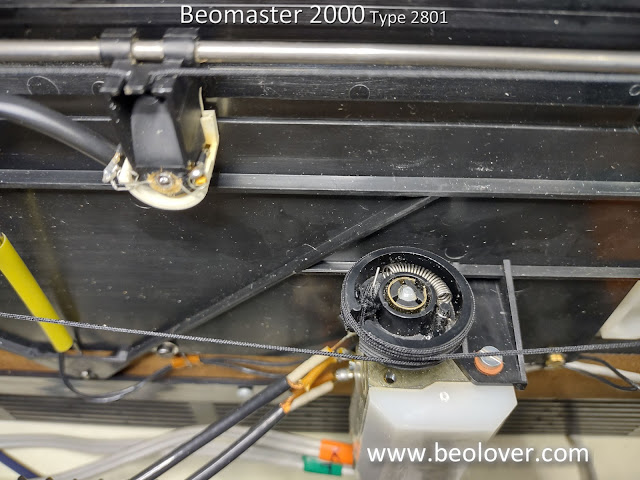
The old, frayed cord has knots on both ends that connect the spring mechanism that secures the cord to the tuning dial pulley.  Having not restrung a dial cord before I did some research on other radio DIY repairs.  I decided the best way for me to go was to make a replacement cord so that I have a knot on each end that, when stretched, measure 44 7/8 inches (114 cm) from the apex of one knot loop to the other.

The type of knot I selected is what is called a "perfection loop" knot.


There are probably better instructional diagrams for this type of knot but I like this one because it shows the apex where I am making my 114 centimeter measurement from.

Once completed I only had to wind the cord around the dial components per the service manual and slip the end loops over the hook in the spring part (that attaches to a post in the pulley).

Here are some photos of the restrung dial cord.


You may have noticed in the photos that the display board was removed from its location.
That is the next restoration step I worked on.

The display board has four lamps (Power On, FM Stereo, Tuning Balance 1 and Tuning Balance 2).


I removed the old double-sided foam tape and replaced it with some modern 3M double-sided tape.
Here are the new lamps I received from Martin Olsen installed.


There is a fifth lamp that I need to replace.  That is the one on the dial pointer.
Power to all the lamps pass through the dial pointer lamp so it has to be present (and not open circuit) for any of the lamps to function.

This is where I ran into a problem.
It turns out that the dial point assembly on this Beomaster 2000 had seen better days and someone had tried some repair work sometime in its past.

Here is what it looks like removed.


The worst part is that someone glued and taped the assembly together.
It is impossible to replace the lamp inside without breaking into the glued casing.

That was my only option.

I was able to salvage the pieces in such a way that I have a pretty good chance of rebuilding a dial pointer assembly from them.


Fortunately I checked with Martin Olsen and he just happened to have a spare Beomaster 2000 (Type 2801) dial pointer assembly.  It is now on its way to me for this project.

In order to continue on with testing the Beomaster 2000 I used a spare lamp holder and connected the replacement dial pointer lamp up so the Beomaster could turn on that the other lamps checked out.


The lamps work now :-).  
The one that is not illuminated works when a station is properly tuned in.

However, the fact that it isn't illuminated in the picture here represented another problem I ran into.

I couldn't tune in any FM stations. When I tried I would hear a very short burst of sound from a station but then it would go dead.  Attempting the station tuning with the muting switch disengaged would allow me to hear faint stations (and no stereo) but as soon as I dialed them in better the sound would go dead.

This problem lead me to monitoring the FM mute signal.
Sure enough, the mute signal was active (about 22V) when a station was dialed in.
When I switched sources to Tape the mute signal would drop down to about -8.3V.

The Beomaster 2000 has a source muting circuit to mute the preamplifier audio to the output amplifier whenever a source selection is made. In addition, there is an FM muting control signal that ties into the audio mute whenever a station is being tuned.

Interestingly, the Beomaster 2000 has a switch to turn the FM station muting on and off.
In this case that function was not doing anything. I always had a muted FM audio signal.

Here is the schematic of the Beomaster 2000 FM muting.
Note that I show two versions of the schematic. One is from the service manual.  The other is drawn up per the way this Beomaster 2000 unit is actually wired.


The service manual schematic shows 2R40 as a trimmer resistor for adjusting the FM muting circuit.
That looked like a good place to start on this Beomaster FM problem...until I went to adjust it and it wasn't there.  

The circuit diagram on the right is how the PCB 2 board is on this Beomaster unit.
I am guessing that perhaps this Beomaster unit is an early serial number (and version) while the service manual shows an improved circuit.  I don't know for certain yet but you can see that there is no trimming resistor specifically for FM muting on the Beomaster 2000 of this project.

Related to the FM muting circuit are the FM Detect Balance and the Indicator Balance circuits (also shown in the diagram).

Each of those circuits have a trimmer resistor for adjustments.

When I changed those I started getting some FM station tuning results and some movement on the problem FM muting signal.

Here is what the actual PCB 2 looked like in the area that goes with the schematic above.


Trimmers 2R28 and 2R31 didn't look like they were in too good of shape.
I replaced them and when I measured them by themselves they did have some dead spots.
I decided to check the transistors while I was de-soldering components.
2TR6, 2IC2 and 2IC 3 all measured good (out of circuit) so I put them back.
The tantalums I spot checked earlier measured right on so I hadn't check the three involved here (2C20, 2C51 and 2C52). These three are 0.1uF capacitors.  When I de-soldered and checked them here, they measured around 0.07uF. So 30% out of tolerance. 

I replaced the trimmers (2R28 and 2R31) and the three 0.1uF tantalum capacitors.

Here is the board after those changes.
I have an oscilloscope probe attached to the FM muting signal for monitoring (while I adjust trimmers 2R28 and 2R31).


Here is a closer look at the FM muting circuit components on PCB 2.


With these changes I was able to adjust the FM Detect balance and the FM Indicator balance trimmers so a tuned in station displays evenly on the two tuning balance lamps, the FM stereo light functions correctly and the audio muting circuit behaves properly.

There are still some additional checks that I want to make and when I receive the replacement tuning pointer assembly I will have to install that.

I have a question I need to figure out the answer for on the display lamps.
When I switch from an FM source to Phono or Tape the bottom tuning balance lamp (IL2) displays at full illumination to match the Beomaster 2000 Power On lamp.

I don't know if that is proper behavior or not. It seems like neither FM indicator lamp should be illuminated if a Phono or Tape source button is pressed.  The Tape source is working well and FM stereo stations are being tuned in. I haven't found any adjustment for that indicator lamp other than the balance trimmers...and they are currently adjusted so that FM signals are received on both channels evenly.

I will have to track down the signal that is causing the IL2 balance lamp to illuminate when a Tape or Phono source is selected.

Monday, February 14, 2022

Beogram 4002 AC Motor Restoration

I recently received an AC platter motor from a Beogram 4002 for restoration. This shows the motor as received:

I removed the pulley, drilled out the rivets and opened it up to extract the rotor and the coil carriers:
Then I submerged the housing halves in motor oil and pulled a vacuum:
Vigorous bubbling started as air was drawn from the assembly.
After 24 hrs the bubbling stopped and I cleaned the parts from excess oil and reassembled the motor. Since the removed threaded rivets cannot be used anymore, I provide 3D printed nut carriers that allow adjusting the motor tilt with two new screws, similar to the original threaded rivets:
If the motor is not associated with a particular Beogram 4002, I always supply additional nut carriers and M3 screws in case the motor is used in a Beogram with belt guides, which also need threaded rivets. See here for an example for a motor with belt guides (usually to be found in earlier Beogram 4000s).


Friday, February 11, 2022

Beomaster 4400 Type 2419: Repairing the Off Switch

I received some parts I had ordered for the current Beomaster projects I have on my workbenches.

For this Beomaster 4400 Off Switch problem I showed in the last post how the switch assembly mechanics were not functioning correctly because of a worn plastic post on the actuator.


The plastic post on the actuator presses against a metal lever to release any source switches that have been engaged. The 2 mm post was not doing its job due to wear.

My options were to find a donor Off switch from a Beomaster 3000, 4000 or 4400 that have that same type of Off switch or to repair the one that I have.

Martin Olsen is sending me a replacement Off switch that he happened to have so that option will be available.  In the meantime I implemented the following repair.

Using a 2 mm inner diameter and 3 mm outer diameter tube of PTSE, I fashioned an outer ring on the original post. That was epoxied in place but I don't fully trust that to hold over long term actuating of the Off switch. So I added an M1 x 4 mm screw and washer to lock everything down.

For the mounting of the screw I originally thought I could use a longer screw and attach an M1 nut to hold it.  However, the location of the plastic actuator post is directly over a plastic support rib of the actuator so there was no room.

I opted for drilling a tiny hole through the actuator post into the plastic just over 4 mm deep.
The screw was then threaded into place to verify the fit.

That worked quite well so I permanently installed the screw with epoxy and an M1 washer.


The new actuator post is now a little larger in diameter than the original.
I trimmed down the edge of the PTFE ring that will make contact with the metal lever using a sharp razor blade. That makes the area where contact with the lever is the correct size to move the lever properly.  Too little, as when the post was worn, results in the lever not moving far enough.  Too much prevents the lever from returning to a position where switches can engage and lock.

After reinstalling the Off switch into the Beomaster 4400 switch assembly it is working properly again.
In the photos below you can see how the actuator post makes contact with the switch assembly control lever.


As the Off switch actuator moves across the bulge of the metal control lever, the lever momentarily presses the switch assembly release bar and any selected source switches become disengaged.

While I have the Beomaster switch assemble out I removed and opened up the phono (PH) switch to see what the contacts look like.  On a previous Beomaster 4400 restoration the source switches later became inconsistent in their ability to route the audio signals when selected.  The selected source would work for a while but eventually, one channel would drop out.  Recycling the source selection switches remedies the problem but it always returns.

Looking at the inside of one the the source selection switches I can see a possible reason why.


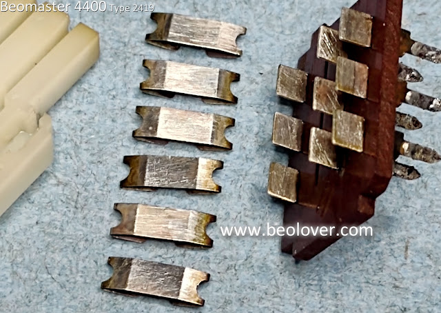
The actuator piece has spring contacts that slide across a set of fixed contacts to make up the switch.
You can see oxidation in the photo on the fixed contacts.  The spring contacts have some oxidation as well. 

If there is enough oxidation on the contacts then just spraying some Deoxit into the switch and operating it will probably not be enough to make it reliable again.

In this case I have completely disassembled the switch where I can scrub the contacts with an abrasive cleaner (like fine grit sandpaper or wire brush).


I coated the contacts with Deoxit fluid after sanding everything.

Reassembly wasn't too difficult. 
I will warn any DIY viewers that when you do this make sure you take precautions to make sure none of the switch components can fall out of the work area.  When dealing with springs there is a high probability that at least one will try to fly off.

That was only one of eighteen switches that need to be opened up and cleaned.
The thought of totally removing the fixed contacts and then gold plating them crossed my mind (briefly).  That would be ideal but it would be quite a big task.  I think I would be looking at approximately 270 contacts.  Quite expensive as well.

One other important note...
This disassembly of the phono source select switch was not too bad because this particular Beomaster 4400 is an early serial number. The metal switch assembly for this model has nice long metal mounting tabs for the switches.  That is not the case for the late model Beomaster 4400 units.  Their switch mounting tabs are tiny and easily break off.  That adds a whole other challenge to cleaning the switches.